CONTROL DATA
CORPORATIONCONTROL
DATA®
217·2
EQUIPMENT CONTROLLER
This Publication Includes Information on the Listed Equ ipments:
FC710-A FC710-B FC711-A FC711-B
• General Description
• Operation and Programm i ng
• Installation and Checkout
• Theory of Operation
• Maintenance
• Maintenance Aids
217-2
EQUIPMENT CONTROLLER
CUSTOMER ENGINEERING MANUAL
BOOKS IN THIS MANUAL:
Book 1 - - General Description
Operation and Programming Installation and Checkout Theory of Operati on Ma i ntenance
Maintenance Aids
Book 2 . - - Diagrams
Any comments concerni ng th is publication should be addressed to:
Publ ication No .. .82128100 April 1969
Contro I Data Corporation Data Display Division Technical Services Department
2401 North Fairview Avenue St. Paul, Minnesota 55113
e
Copyright 1969 Control Data Corporation217-2 Equipment Controller
CUSTOMER ENGINEERING MANUAL - BOOK 1
REVISION RECORD
REVI S ION
DESCRIPTION
A-O-O Released
(8/68)
~
. "
~~ll:t~.LI!&C':·A~'"
:ft\'/RSIISI~"
--
...
. """
DOl 219 REV 3/68
82128100
217-2
Equi pment Controller
Customer Engi neeri ng Manual
Book 1
EQUIPMENT CONFIGURATION
The FCO and configuration levels for each equipment discussed in th is document are listed in Book 2 (pub-lication number 82128200) of th is manual.
217
FOREWORD
The purpose of this manual is to provide a systematic approach to the funda-mental operating principles of the 217-2 Equipment Controller. This book (Book 1 of 2) covers two major areas: Theory of Operation (Section IV) and Maintenance (Section VI). Remain ing sections provide support information.
• Section I, General Description - acquaints the reader with the structure of the controller while providing physical, electrical, and e nv i ronmen ta I pa ramete rs •
• Section II, Operation and Programming - describes all switches, indi cators, and controls located on or with in controller cabinetry. Programming is generally on a systems basis. See the 200 User Terminal Reference Manual (publication number 82128000) for details.
• Section III, Installation and Checkout - lists the procedures required to make the controller operationa I from the in itia I uncrating state.
• Section IV, Theory of Operation - intended both for the general reader and the more experienced customer engineer. The approach used divorces the reader from the logic prints and explains internal operations with the aid of block and flow diagrams.
• Section V, Diagrams - this section is contained in Book 2 (publication number 82128200). The approach taken features detailed descriptions interlaced with the logic diagrams yielding a second "theory. II
• Section VI, Maintenance - detai led description of adjustment points as well as preventive maintenance procedures. For physical orientation, cross-reference Sections I and II.
• Section VII, Maintenance Aids - additional miscellaneous information which might aid in servicing the controller.
217
FOREWORD (CONT)
NOTE
Refer to the 217-2 Equipment Controller Parts List (publ ication number 82128400) for parts information.
The characteristic feature of th is controller is its abi I ity to increase its data processing scope by adding other peripheral units. A special adapter kit is required for each i/o device added. These adapters consist mainly of additional logic boards to be installed in the controller logic rack. Accordingly, both books maki ng up this Customer Engi neering publ ication describe the adapters in detai I. For specifications on the units, consult the associated documentation supplied.
217
TABLE OF CONTENTS
Section Page
I GE NERAL DE SCRIPTION
Physical Data
1-3
Environmental Data
1-4
Electrical Data
1-4
II OPERATION AND PROGRAMMING
III INSTALLATION AND CHECKOUT
PART A - BASIC CONFIGURATION
Unpacking
3-1
Cabling
3-1
Assembly
3-5
Checkout
3-7
PART B - CARD READER ADAPTER KIT
Cabling
3-1
Checkout
3-1
PART C - TYPEWRITER ADAPTER KIT
Cabling
3-1
Checkout
3-1
PART D - LINE PRINTER ADAPTER KIT
Cabling
3-1
Checkout
3-1
PART E - CARD READE R ADAPTER KIT
Cabling
3-1
Checkout
3-1
Section
IV
217
TAB LEO F CON TEN T S ( CON T )
THEORY OF OPERATION
PART A - BASIC CONFIGURATION
Main Timing Master Clock Timing Chain Pass Counter Clock Pulses Display Control
Window
Display Register Position Counters Keyboard Control
B~ckspace
Skip _Line Skip
Carriage Return Reset Clear Send Interrupt Print Repeat Line Counter Symbol Gene rator Interface
Initial Contact Automati c Answering Data Transmission Message Format Rece ive Operation
Word Parity Message Parity
Poll Message Alert Message
217
T AS LE OF CO NTENTS (CONT)
Section Page
IV Write Message
4-38
Reset- Write and CI ear- Write Messages
4-41
Diagnostic Write Message
4-41
Transmit Operation
4-43
Acknowl edge Message
4-45
Reject Message
4-46
Error Message
4-46
Read Message
4-47
Redundant Responses
4-51
PART S - CARD READER ADAPTER KIT
General Operation
4-3
Data Entry
4-7
Data Transfer
4-8
Load
4-8
List
4-9
Test
4-9
Skip
4-10
Interrupt
4-10
PART C - TYPEWRITER ADAPTER KIT
General Operation
4-2
Uppercase/Lowercase
4-2
Space
4-4
Carriage Return
4-5
Data Translations
4-8
Printout Termination
4-8
Interrupt
4-10
PART D - LINE PRINTER ADAPTER KIT
General Operation
4-1
Line Truncation
4-3
Format Control
4-5
Printout Term ination
4-7
217
TABLE OF CONTENTS (CONT)
Section Page
N
Test Mode 4-7Interrupt 4-7
PART E - CARD READER ADAPTER KIT
General Operation 4-3
Data Entry 4-6
Data Transfer 4-6
Load 4-6
List 4-7
Interrupt 4-7
Test 4-8
V DIAGRAMS
VI MAINTENANCE
Preventive Maintenance 6-1
Test Equipment Required 6-1
Corrective Maintenance 6-2
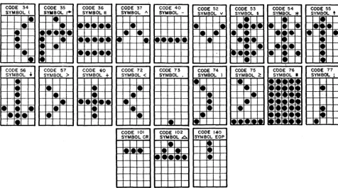
Video Pulse Adjustments 6-3
Ramp Generator Adjustments 6-5
Automatic Answering Adjustment 6-5
Delay-Line Memory Adjustment 6-7
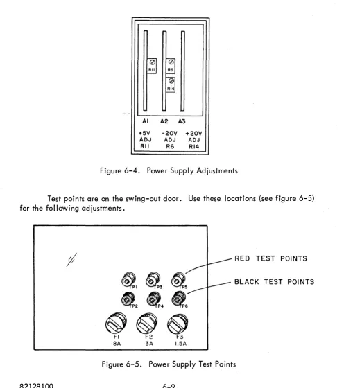
Power Supply Adjustments 6-8
Power Supply Troubleshooting 6-10
+ 5- Vol t Supply 6-10
+ 20-Volt Supply 6-11
- 20-Volt Supply 6-12
Transformer 6-13
VII
-
MAINTENANCE AIDSSymbol Timing and Formation Matrix 7-1
Card Schematic Diagrams and Assembly Drawings 7-3
217
SECTION I
GENERAL DESCRIPTION
The basic Equipment Controller is designed primari Iy for Display Station entry and retrieval communications with a central processing site (data source). All data entered from the Display Station keyboard and all communications with the data source form a crt display.
Equipment Controller design also allows for the modular addition of other entry or retrieval devices to the basic configuration. These add itional devices include a card reader and/or a printer. The printer may be a typewriter or a high-speed line printer. For each unit added to the basic configuration, a special adapter kit must be installed in the Equipment Controller.
Each adapter kit contains a 1 O-mi lIisecond delay-line memory and the logic necessary to form a module governing the operation of the assoc iated unit. This memory, in addition to providing data storage facilities for the associated unit, adds to the overall buffering network. The basic module governing Display Station opera-tion also contains a delay-line memory so the overall buffering scheme in the control-ler appears as:
DATA SOURCE
82128100
EQUIPMENT
----,-- CONTROLLER 1 4 - -... ,
INTERFACE
DISPLAY STATION
DISPLAY MODULE
Bu fferi ng Sc heme
1-1
MAY OR MAY NOT CONTAIN ADDITIONAL
BUFFERING
ADAPTER KIT
(MODULE)
\
General Description
217
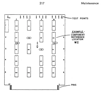
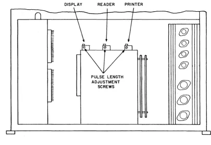
Section IThe next group of illustrations point out the structure of the controller; co II i ng out suc h i terns as delay lines I power supp Iy, etc.
POWER SUPPLY (SWING-OUT DOOR)
DISPLAY STATION OUTLET AND FUSES FOR DISPLAY STATION AND A-C INPUT
Rear View (Panel Removed)
SYMBOL GENERATOR (DIODES,DIODE DRIVERS
AND DIODE RECEIVERS)
DELAY LINES DL I-DISPLAY DL 2-ADAPTER DL 3-ADAPTER
ROWA
LOGIC CHASSIS (SIDE VIEW) ROW B
POWER CABLING TERMINAL STRIP
LOGIC CHASSIS ROW A
ROW B
SWITCH PANEL
Left S ide Vi ew (Pane I Removed)
Section I
+20-VOL T D-C OUTPUT (F USE AND T EST POI NTS)
-20-VOL T D-C OUTPUT (FUSE AND TEST POINTS)
+5-VOL T D-C OUTPUT (FUSE AND TEST POINTS)
PHYSICAL DATA.
217
General Description____ SWiTCH/INDiCATOR PANEL
Right Side View (Panel Removed)
POWER SUPPLY (SWI NG-OUT DOOR)
The Equipment Controller may be located as desired within the limitations of size, weight, and environmental conditions. Dimensions and weight are shown in the next illustration.
WEIGHT-I25 POUNDS
General Description 217 Section I
ENVIRONMENTAL DATA.
Temperature, relative humidity, and altitude limitations under both opera-tiona I and nonoperaopera-tional conditions are I isted next. Operaopera-tional condition means that the unit should function properly if normal operating procedures are followed. Nonoperational condition means that the unit is capable of operation after storage and transit under listed environmental conditions, providing it is properly packaged.
ENVIRONMENT AL CONDITIONS
CONDITION OPERATIONAL NONOPERATIONAL
Temperature +60 to +85
F
- 30 to + 150F
Relative Humidity 10 to 90010 5 to 100% (includes condensation)
Altitude - 1 000 to + 1 0, 000 ft - 1 000 to + 15, 000 ft
The Equipment Controller uses ambient air for cooling by radiation and convection, therefore, air ducts are not necessary. Heat dissipation is about 441
Btu per hour when equipment is in operation.
ELECTRICAL DATA.
A-c power requirements for the Equipment Controller are as follows:
105 to 125 vac, 47 to 400 hertzr 1.0 ampere
(60-hertz i nsta lIations)
OR
210 to 250 vac, 47 to 400 hertz, 0.5 ampere (50-hertz i nsta Ilations)
D-c outputs are fused on the power supply door (see page 1-3). The follow-ing list gives fuse types and current ratfollow-ings.
Section I
TYPE
3AB AGC 3AG
217 Genera I Description
D-C OUTPUT FUSES
SIZE (Amperes)
8.0 3.0 1 .5
DESCRIPTION
+5-volt d-c output (F1) - 20-vo It d-c output (F2) + 20-volt d-c output (F3)
Display Station and controller power supply a-c input power is fed through the two fuses on a box in the lower rear of the controller (see page 1-2). Modem a-c input passes through the fuse in the modem cubicle (see page 1-2). The next two lists show fuse types and current ratings for both 60- and 50-hertz installationse
TYPE
3AG Sio Blo 3AG
510
Blo 3AG510
BloTYPE
MDX Sio Blo MDA Sio Blo MDL Sio Blo
82128100
60-HERTZ A-C INPUT FUSES
SIZE (Amperes)
2.0 5.0 0.5
DESCRIPTION
Display Station a-c input (F1) Power Supply a-c input (F2) Modem a-c input (F3)
50-HERTZ A-C INPUT FUSES
SIZE (Amperes)
1.25 3.0 0.5
1-5
DESCRIPTION
217
SECTION II
OPERATION AND PROGRAMMING
This section provides supplemental information to the discussion of the Equipment Controller's role in the Remote User Terminal operation and programming presented in the Reference Manual. The supplemental information concerns itself only with the operation of controls located on or within the Equipment Controller.
Programming is generally on a total equipment basis which is the fundamental approach of the Reference Manua
I.
Two switch panels govern most of the controller operations. One of these is located on the right rear corner of the toble top and is directly accessible to the operator.
Switch/Indicator Panel
Operation and Programming
SWITCH/INDICATOR
LINE/BLOCK
POWER ON
ON LINE
MAN REL
(Manua I Rei ease)
LIST
LOAD
217 Section II
FUNCTION
Alternate action, illuminated pushbutton - when LINE is illuminated, the line indicator is used in communications and message composition. BLOCK position prevents use of the line indicator.
An alternate action, i lIumi nated pushbutton. De-pression resu Its in appl ication of primary power to the Equipment Controller and an initial master clear of logic. The lens is illuminated while power is on. A second depression turns power off.
Indicator illuminates when the equipment is trans-mitting or receiving information.
A momentary action, lighted pushbutton unlocks the keyboard for operator use when activated. In addi-tion, the entry marker is reset without affecting dis-played data and the interface is cleared.
A momentary action, lighted pushbutton which ini-tiates a read operation from the card reader to the printer. Data is not displayed or transmitted to the data source. Completion of printout extinguishes the light a~ returns the Equ ipment Controller to an inactive state.
A momentary action, I ighted pushbutton enables a read operation from the card reader to be performed. Subsequent data transm issions are under control of the data source. Read operation completion turns off the light.
The remaining set of switches are on the bottom of the logic assembly. This assembly is accessible through the left panel of the Equipment Controller cabinet
(see page 1-2).
Logic Assembly Switches
Section II
SWITCH
INT BCD/EXT BCD
ALARM TEST
AUTO ANSWERING
ERROR ENABLE/DISABLE
POLL NORMAL/WAIT
2 WIRE/4 WIRE
READER TEST/MC
PRINTER TEST
82128100
217
Operation and Programm ingFUNCTION
INT BCD position - enables transmission and interpretation of received data in internal binary coded decimal format. EXT BCD position
-=-enableS-transmission and interpretation of received data in external ,!:inary coded ~ecimal format.When placed in the ON position, this switch acti-vates the ALERT light and alarm on the Display Station. The alarm cannot be turned off at the Display Station keyboard. This switch serves as a maintenance feature.
Activation of this switch allows the controller to operate with the automatic answering feature.
ENABLE position - allows transm ission of an error message, shou Id an error condition arise. DISABLE position - blocks tra'nsmission of any pend i ng error messages.
NORMAL position - controller transmits a reject message in response to a poll if no read message is pending. WAIT position - controller transmits an acknowledge message in response to a poll if no read message is pending. Any subse-quent read message is then transm itted without the aid of another poll, as long as no other message is received in the meantime.
Allows modem connection in either 2- or 4-wire half duplex.
TEST position - initiates a read operation at the card reader. Data is transferred to the display memory for observation on the crt. MC position -momentary action in wh ich controller and adapter kits are master cleared.
Prevents completion of print operation (except for a manual reJease or master clear condition) caus-ing continual printout ofa message while switch is in the ON position.
217
SECTION III
INSTALLATION AND CHECKOUT
This section contains unpacking, assembly, and checkout information for the Equipment Controller including adapter kits. A rigid preshipment, qual ity control check ensures proper performance. If any problems occur, refer to Section VI, Mai ntenance, in this book.
To facilitate the use of test equipment during periods of maintenance, Control Data requires that a convenience outlet be available within 15 feet of each system component cabinet. The outlets may be located in the walls or ra ised floor pane Is of the equ i pment room and must not be obstructed by storage racks or other furniture. The receptacles shall be of the single-phase grounded type, installed according to local electrical codes. For 60-hertz installations, the nominal voltage shall be 120 volts. For 50-hertz installations, the nominal voltage shall be 220, 230, or 240 volts as dictated by the single-phase power available at the site.
PART A
BASIC CONFIGURATION
Covering
Equipment Controllers:
FC710-A FC710-B FC711-A FC711-B
For use with Display Stations:
Section III
217
Installation and Checkout Basic ConfigurationUNPACKING.
The Equipment Controller is shipped in a cardboard carton attached to a special skid. Remove the carton and all tape, straps, and padding. The packing materials, containers, and skid should be saved for reuse in event of reshipment.
Remove the Equipment Controller side panels and check to see that all com-ponent mounting hardware is securely fastened, and that all boards are securely inserted in their respective connectors. Check the power supply door for freedom of movement.
CABLING.
One end of an 8-foot modem cable is wired directly into the Equipment Controller logic assembly. The other end is terminated in a small gray connector which plugs into the receptacle provided on the modem. Following are the modem cable pin assignments.
MODEM DATA CABLE
PIN DESIGNATION SIGNAL ORIGIN
1 Protective Ground Modem and Controller
2 Transmitted Data Controller
3 Received Data Modem
4 Request to Send Controller
5 Clear to Send Modem
6 Data Set Ready Modem
7 Signal Ground Modem and Controller
8 Data Carrier Detector Modem
9 Reserved for Data Set Testing Not Used
10 Reserved for Data Set Testing Not Used
11 Not Used
12 . Not Used
13 Not Used
14 New Synchronization Not Used
15 Transmitter Signal Element Timing Modem
16 Dibit Clock Transmit Not Used
17 Receiver Signal Element Timing Modem
18 Dibit Clock Receive Not Used
19 Not Used
20 Data Terminal Ready Controller
21 Not Used
22 Ring Indicator Modem
23 Not Used
24 Transmitter Signal Element Timing Not Used (External Timing Input)
25 Not Used
Installation and Checkout
MODEM A-C POWER
CABLE
TO PHONE
LINES - - t -_ _
FROM MODEM
217
-Basic Configuration
60 HERTZ INSTALLATION
(REAR VIEW)
Section III
MODEM ----,-DATA
CABLE
J2 is not used in 50-hertz installations. In this case, the modem power cable must be connected to terminal strip TB3 as shown in the next illustration. The terminal strip is on the front side of the pane I so the cab Ie must be routed through one of the holes.
TB3 YELLOW
GREY
220V---r---~~~ GROUND
0
I
MODEM DATA
CABLE
Part A
NEUTRAL
CONNECTOR PANEL - 50 HERTZ
(FRONT VIEW)
Section III 217 Insta Ilation and Checkout Basic Configuration
One end of a 6-foot Display Station data cable is wired directly into the logic assembly. The other end contains a large metal connector for the receptacle at the rear of the Display Station. Following are the Display Station data cable pin assignments. The cable consists of 21 twisted pair and four coaxial lines. Unlisted pi n numbers are not used.
DISPLAY STATION DATA CABLE
PIN NO.
1
2
3
4 5 7 8 9 10 . 1112 13 14 15 16 18 19 20 21
22
23
24 25 26 27 34 38 40 SIGNALData Bit 0 Data Bit 1 Data Bit 2 Data Bit 3
Horizontal (Coaxial Line) Vertical (Coaxial Line) Data Bit 4
Data Bit 5 Data Bit 6 Clear Key Strobe Repeat Key Function Strobe Send Index Key Interrupt Key Ground Ground Ground Ground Ground Ground Alarm Disable Alert Light
U nattended/ Attended Light Unattended/Attended Switch Alert Alarm
Video (Coaxial Line) Diddle (Coaxial Line)
The Display Station data and a-c power cables must be routed through the hole in the lower rear panel. For 60-hertz installation, connect the power cable to J 1 at the bottom. The cable is connected to TB2 at the same point for 50-hertz i nsta lIati ons.
Installation and Checkout
HOLE IN BACK
PANEL
DISPLAY STATION A-C POWER
CABLE
60 HERTZ
FI F2
(;j
(!)
MONITOR
Part A
217
Basic Configuration
DISPLAY STATION
(REAR VIEW)
TO DISPLAY
STATION {
WHITE
BLACK
GREEN
Cabling Diagram
Section III
DISPLAY STATION
, - - DATA CABLE
HOLE IN BACK
PANEL
50 HERTZ
FI F2
(!j
MONITOR
Section III 217 Insta lIati on and Chec kout Basic Configuration
The Equ ipment Controller a-c power cab Ie and adapter kit data cab les are routed through the bottom. Adapter kit connections are described in the applicable Reference/Customer Engineering Manua Is. The a-c power cab Ie requ ires a standard sing Ie-phase grounded out let for 60-hertz insta I lations . For 50-hertz insta Ilations, the cable is· not terminated in a connector. The power cable consists of 3 18-gauge wires, and for 50-hertz insta Ilations, the wire assignments are:
ASSEMBLY.
Black - 220 volts White Neutral Green . - Ground
The Equ ipment Controller is sh ipped fu Ily assembled. All that remains is to install interconnecting cables.
1 . Refer to the Disp lay Station Reference/Customer Engineering Manua I (publication no. 82136300) for monitor assembly instructions.
2. Plug in Display Station data cable.
3. Attach Disp lay Station a-c power cable.
4.
Plug in modem data cables.5. Connect modem power cable.
CAUTION
Modem power cab Ie shou rd not be connected before data cab les are attached.
6. Place modem in cubicle provided in controller.
7.
Reseat all logic cards.8. Connect Equipment Controller a-c power cable.
Installation and Checkout 217 Section III Basic Configuration
The lower four bit positions of the controller site address are determined by the four slide switches on the board in jack B 12. The least significant bit is the lowest switch position whereas the most significant bit is the top switch position. A logical 0 is entered in a bit position when the switch is in the outside position. System requirements determine what the actual address should be.
8
01 02 03 04 05 06 07 08 09 10 II 12 13 14 15 16
LOGIC RACK
SITE
---~ ADDRESS
SWITCHES
The final steps involve the switch panel located on the logic rack (see description in Section II). System requirements determine the positions of most of these switches.
Part A
1 • The position of the INT/EXT BCD switch is determined by the code set used at the central processing site.
2.
AUTO ANSWERING may only be used if the modems are capable of such operation.Section III
217
Insta Ilation and Checkout Basic Configuration3. Place the ERROR ENABLE/DISABLE switch in the ENABLE position if the data sou rce recogn izes an error message. Otherwise, use the DISABLE position.
4. POLL NORMAL/WAIT can be placed in the WAIT position only if the terminal is the only site on the common carrier.
5. The 2-WIRE/4-WIRE switch should be in a position corresponding to the modem strapping option employed.
6. Use the ALARM TEST switch to turn on the Display Station alert alarm for volume adjustment purposes (see Display Station Reference/Customer Engineering Manua I).
7. READER TEST and PRINTER TEST switches are explained in associated adapter kit Reference/Customer Eng ineering pub Ii cati ons.
CHECKOUT.
The following chart depicts a simplified checkout procedure assuming all cables have been properly installed. Use Sections VI and VII and the Display Station Reference/Customer Engineering Manual in the event any adjustments are required or malfunctions occur.
Installation and Checkout
217
Section III Basic ConfigurationDEPRESS POWER ON
SWITCH/ INDICATOR
PANEL
FILL RASTER WITH VARIOUS SYMBOLS INDICATOR ILLUMINATED YES ROTATE ON/OFFj INTENSITY CLOCKWISE RASTER VISIBLE
FUSE ON REAR OF DISPLAY STATION OK
NO CHECK OUT
PERFORMANCE THROUGH
CENTRAL PROCESSING
SITE SEE VIDEO PULSE AND DELAY-LINE ADJUSTMENTS IN SECTION VI AS WELL AS ADJUSTMENTS SPECIFIED IN THE DISPLAY STATION
REF ICE MANUAL
NO
REPLACE FUSE
A-C INPUT
(F2)
FUSE OK
YES YES CHECK INPUT POWER NO REPLACE FUSE REPLACE LAMP
r
-I
I II
DISPLAY FJ6
- - - ,
I II
II
I IF2 I
..J
MONITOR
STATION fUSE REPLACE
IN CONTROLLER FUSE
(FJ) OK
YES
SEE POWER SUPPLY ADJUSTMENTS
IN SECTION VI
CHECK RAMP GENERATORS ADJUSTMENT
(SEE SECTION VI)
Simplified Checkout Procedure
PART B
CARD READER ADAPTER KIT
Equipment Numbers
FE 1 05-A FE105-B FE106-A FE106-B
For use with the 224-1 Card Reader Station, Equipment Numbers:
Section III 217
Typewriter Adapter Kit
Installation and Checkout
An adapter kit must be installed if the controller is to drive a 218-1 Type-writer Station. The following illustration points out adapter kit board, cable, and
jumper locations in the controller logic rack. Refer to the 218-1 Typewriter Station Reference/Customer Eng.ineering Manual for specificat"ions on the typewriter.
16 17 18 19 20 21 22 23 24 25 26 27
w ...J
a::: a:::
0 0 0 0 0 0 m
w w 0 <t
a. a. <l IJ.. (!) <l J: 0
«
u B:!: :!:
~ (I) (I)
«
(I) (I) <l <t~ ~ I'- I'- I'- I'- I'-
l"-) ...., ...., t-<t
0
Typewriter Adapter Placement
CABLING.
One end of the 15-foot typewriter data cable terminates in a 62-pin board while the other terminates for connection to the typewriter. Insert the board end in
B27. The next I ist calls out pin assignments for the cable. Odd-numbered board pins are on the soldered side with even numbers on the other side. Pin numbering is sequential from top to bottom. As an example, the upper pin on the soldered side is pin 1, while the adjacent pin on the other side is pin 2. Unlisted pin numbers are not used.
CHECKOUT.
An operational check qf the typewriter can be performed locally through the use of the Display Station.
1. Equipment Controller POWER ON to ON (illuminated) position.
2. Display Station ON/OFF/INTENSITY to ON position.
3. Typewriter ON/OFF rocker switch to ON position.
4.
Feed paper from tray up through tractor assembly.5. Compose message using Display Station keyboard.
6. Depress AUX SEND key when composition is completed.
7. Displayed message is typed up to the E2
C)
symbol as an image of the crt display.Installation and Checkout
DESIGNATION
Norma Ily Open Normally Closed Carriage Return Space
Upper Case Lower Case Rl R2 R2A R5 Tl T2 CK
Keyboard Lock End of line +20 Volts
Paper Low (Ready) Ground
- 50-Volt Ground Return
217
Typewriter Adapter Kit
TYPEWRITER DATA CABLE
CONNECTOR BOARD
PIN PIN
A 3
C 5
E 7
F
8H 11
J 12
K 13
L 14
M
15N 16
P 17
R 18
S 19
T 20
V 56
X 33
Y 25
Z 31
a 27
Section III
SIGNAL ORIGIN
Typewriter Typewriter Controller t Controller Typewriter Controller Typewriter
---If a card reader is a member of the configuration, a local printout of punched card data is possible (without display). In th is case, the Display Station is not used since the message consists of punched cards. After making the reader operational and loading cards, all that remains is to depress the LIST switch. Printout is in 12-card batches until the hopper is empty. Each print line is one 12-card in length (up to 80 symbols).
A final check can be made via programming at the central processing site. Each write message received (ending with escape and E2 codes) initiates a printout which is an exact image of the crt presentation.
Section III 217 Installation and Checkout Card Reader Adapter Kit
If a printer is also included in the configuration, it may also be used to monitor reader operation. The same steps should be followed. Instead of rotating the Display Station ON/OFF/INTENSITY control, ensure the printer is ready. Then, depress the LIST switch on the controller table top in place of using the READER TEST/MC switch. With this method, 12-card batches of data will be read and printed {without display} until the hopper is empty. The Display Station keyboard remains unlocked during this interval.
The fi nal check is via programm ing at the central processing site {LOAD mode}. Here, each write message ending with an escape code followed by E3 ini-tiates transmission of a 12-card batch of data. A simu Itaneous display occurs. The Display Station keyboard is locked out during LOAD mode. A write message from the data source (ending with an E1 code), master clear, or manual release is required to perform the release.
PART C
TYPEWRITER ADAPTER KIT
Equipment Numbers
FF305-A FF305-B FF306-A FF306-B
For use with the 218-1 Typewriter Stat ion, Equ i pment Numbers:
Section III 217 Installation and Checkout
Li ne Pri nter Adapter Kit
In order to drive a 222 line Printer, the Equipment Controller must contain an adapter kit. Board, cable, and jumper locations in the logic rack are shown next. For information on the line printer, reference the 222 Line Printer Controller Reference/Customer Engineering Manual.
16 17 18 19 20 21 22 23 24 25 26 27
UJ ....J
a:: a:: 0 m
UJ UJ 0 0 0 0 <!
a.. a.. I- (f) :::J 0 ... 0
B
~ ~ a:l U a:l (D (D
«
)
::::>.., ..,
::::> I"- 00 f'- I'- I"-...
<!0
Line Printer Adapter Placement
CABLING.
One end of a 15-foot line printer cable connects to a 62-pin board while the other terminates for connection to the line printer. Insert the board end in B27.
Followi ng are pi n assignments for the cable. Odd-numbered board pi n~ are on the soldered side with even numbers on the other side. Pin numbering is sequential from top to bottom. For example, the upper pin on the soldered side is pin 1 while the adjacent pin on the other side is pin 2. Unlisted pin numbers are not used.
CHECKOUT.
The following procedure should be observed to locally check line printer operation.
1. Equipment Controller POWER ON to ON (illuminated) position.
2. Displdy Station ON/OFF/INTENSITY to ON position.
3.
Printer POWER ON switch to ON position.4.
Depress printer PAGE EJECT.5. Insert paper in tractor assembly.
6. Activate START button.
7. Compose message using Display Station keyboard.
Installation and Checkout 217 Section III Line Printer Adapter Kit
8. Depress AUX SEND when composition is complete.
9. Displayed message is printed up to the E2
C)
symbol.LINE PRINTER DATA CABLE
DESIGNATION CONNECTOR BOARD SIGNAL ORIGIN
PIN PIN
Data Bit 0 A 3 Controller
Data Bit 1 B 4
Data Bit 2 C 5
Data Bit 3 D 6
Data Bit 4 E 7
Data Bit 5 F 8
Data Bit 6 H 11 Contro.ller
Ground b 29
Informati on Ready R 18 Controller
Output Resume S 19 Printer
Master C
I
ear U 21 ControllerReady
W
23 PrinterPrint Mode X 24 Controller
Not 136 Colun.n
V
22 PrinterThe PRINTER TEST switch on the logic rack may be used to cause a con-tinual printout of the same message. This switch blocks recognition of the E2 symbol.
If a card reader is avai lable, punched card data may also be printed locally (without display). After making the reader operational and loading cards, all that remai ns is to depress the LIST switch. Pri ntout is in 12-carcl batches unti
I
the hopper is empty. Each print line is one card in length (up to 80 symbols). Here, again, the PRINTER TEST switch may be used.The final step is to check printer operation through the central processing site. Each write message received (ending with escape and E2 codes) initiates a
printout wh ich is an exact duplicate of the crt presentation. The PRINTER TEST switch may be used in this instance also.
PART D
LINE PRINTER ADAPTER KIT
Equipment Numbers
FF512-A FF512-B FF513-A FF513-B FF514-A FF514-B FF515-A FF515-B
For use with the 222- 1 and 222-2
Line Printer Stations, equi pment numbers:
Section III 217 Installation and Checkout Card Reader Adapter Kit
In the event a 224-1 Card Reader is part of the configuration, a card reader adapter kit should be installed in the logic rack. The next chart shows the location of logic boards, jumper, and cable comprising the package. Refer to the 224-1 Card Reader Station Reference/Customer Engineering Manual for details on the reader.
01 02 03 04 05 06 07 08 09 10 \I 12 1
w ...J
ID
0 Cl Cl 0 0::: 0:::
« 0 0 w w
B u -:> <! m ::::> u 0 0.. 0..
en :J: :J: 0 :J: (l) :!: :!:
« I"- co ex> 00 ex> I"- ::::> ::::>
t- ...., ....,
«
0
Card Reader Adapter Placement
CABLING.
The data cab Ie for the card reader is 15 feet long and one end termi nates in a 62-pi n board wh i Ie the other end contai ns a rectangu lar connector. Insert the board end in location B01. The other end connects to the card reader. Follow i ng is a I ist of pin assignments for the cable. Odd-numbered board pins are on the soldered side of the board with even numbers on the other side. Pin numbering is sequential from top to bottom. As an example, the upper pin on the soldered side
is pin 1, while the adjacent pin on the other side is pin 2. Unlisted pin numbers are not used.
CHECKOUT.
The READER TEST/MC switch on the logic rack initiates an operational check of the reader. With the Display Station and Equipment Controller functioning prop-erly, punched card data may be monitored at the Disploy Station with the switch in the TEST position. During this period, the Display Station keyboard is locked out. A power on master clear or manual release is required to perform the release, once the switch has been taken out of the TEST position.
1. Equipment Controller POWER ON to ON (illuminated) position.
2. ON/OFF/INTENSITY control to ON position.
3.
READER TEST/MC switch to TEST position.4. Load reader hopper with punched cards.
Insta Ilation and Checkout
217
Section III Card Reader Adapter Kit5. Reader MAN/AUTO switch to AUTO position. 6. Reader ON/OFF switch to ON position. 7. Depress reader REG switch.
8. Punched cards wi II be read and d isp layed unti I the hopper is empty.
CARD READER DATA CABLE
DESIGNATION CONNECTOR BOARD SIGNAL ORIGIN
PIN PIN
+5
Volts DC L, P, K1, 2, 61
ControllerRegister U
6
Card ReaderSkip
W
8
Not Skip X
11
Pressure Rollers Down
Y
12
Column
82
a13
Manual/Auto S
4
Card Present m
19
Clock n
20
Field p
21
Row
12
HH43
Row
11
FF42
Row
0
EE41
Row
1
DD40
Row
2
CC39
Row
3
BB38
Row
4
AA37
Row
5
z36
Row
6
y35
Row
7
x28
Row
8
w27
Row 9 v
26
Card ReaderEscapement d
14
ControllerReady s
23
I
Check Reader r
22
- 20
Volts DC E, M29, 30
+20
Volts DC J33
ControllerPART E
CARD READER ADAPTER KIT
Equ ipment Numbers
FE108-A FE108-B FE109-A FE109-B
For use with the 224-2 Card Reader Station, Equipment Numbers:
Section III
217
Installation and Checkout Card Reader Adapter Ki tA 224-2 Card Reader Station becomes a member of the configuration when this adapter is properly installed. The next chart shows the location of logic boards, jumper, and cable comprising the package. Refer to the 224-2 Card Reader Station Reference/Customer Engineering Manual for details on the reader.
01 02 03 04 05 06 07 08 09 10 II 12 I
w ...J
al 0:: 0::
B U ct 0 N 0 0 0 N lL. 0 lL. 0 0 lL. 0 0 0 0 0.. W LLI 0..
ct lL. I'- I'-U I'-(!) I'-U U I'- U I'- --, Cl) CD I'- ~ ~ :::> :::>
....
.,
.,
ct
0
Card Reader Adapter Placement
CABLING.
The data cable for the card reader is 15 feet long and one end terminates in a 62-pin board. Insert the board end in location
BDl.
The other end connects to the card reader. Following is a list of pin assignments for the cable. Odd num-bered board pins are on the soldered side of the board with even numbers on the other side. Pin numbering is sequential from top to bottom. As an example, the upper pin on the soldered side is pin 1, while the adjacent pin on the other side is pin 2. Unl isted pin numbers are not used.CHECKOUT.
The READER TEST/MC switch on the logic rack initiates an operational check of the reader. With the Display Station and Equipment Controller function-ing properly, punched card data may be monitored at the Display Station with the switch in the TEST position. During th is period, the Display Station keyboard is
locked out.
A
power-on master clear or manual release is required to unlock the keyboard once the switch has been removed from the test position.Installation and Checkout 217 Section III Card Reader Adapter Kit
CARD READER DATA CABLE
DESIGNATION CONNECTOR BOARD SIGNAL ORIGIN
PIN PIN
Feed C 59 Controller
Ground H 60
Ready A 51 Reader
Ground E 52
Check Error D 58 Reader
Ground J 57
Strobe B 50 Reader
Ground F 49
End Data
M
07 ReaderGround S 08
Channell K 14 Reader
Ground P 13
Channel 2 N 19 Reader
Ground T 20
Channel 3 L 22 Reader
Ground R 21
Channel 4
W
25 ReaderGround
-
a 26Channel 5
U
28 ReaderGround
Y
27Channel 6 X 35 Reader
Ground
b
36Channel 7 V 38 Reader
Ground Z 37
Channel 8
e
41 ReaderGround
k
42Channel 9 c 44 Reader
Ground
11
43Channel 0
r
11 ReaderGround m 12
Channel 11
d
06 ReaderGround
r
05Channel 12
r-
03 ReaderGround
v
04Ground j5' 09
Ground IT 31
Ground
z
32Ground DD 54
Section III 217 Installation and Checkout Card Reader Adapter Kit
1. Equipment Controller POWER ON to ON (illuminated) position.
2. ON/OFF/INTENSITY control to ON position.
3. READER TEST/MC switch to TEST position.
4.
Load reader hopper with punched cards.5.
Reader MAN/AUTO switch to AUTO position.6. Reader ON/OFF switch on front panel to the ON (up) position. 7. Depress READY/CHECK (READY should light).
8. Depress FEED/ERROR (FEED should light).
9. Punched cards wi
II
be read and displayed until the hopper is empty or an error occurs. Since a hopper-empty situation is created before thelast card can be scanned, this card should be blank or contain non-essential information.
If a printer is also included in the configuration, it may also be used to monitor reader operation. The same steps should be followed. However, instead of rotating the Display Station ON/OFF/INTENSITY control, ensure the printer is ready. Then, depress the LIST switch on the controller table top in place of using the READER TEST/MC switch. With this method, 12-card batches of data wi
II
be read and printed (without display) untiI
the hopper is empty. The Display Station keyboard remains unlocked during this period.The final check is via programming at the central processing site (LOAD mode). Here, each write message ending with an escape and E3 code initiates transmission of a 12-card batch of data. A simultaneous display occurs. The Dis-play Station keyboard is locked out during LOAD mode. A write from the data source (ending with an El code), master clear, or manual release is required to unlock the keyboard.
217
SECTION IV
THEORY OF OPERATION
The approach taken in the theory of operation for the Equipment Controller is from a functional viewpoint. Such a systematic approach eliminates the necessity for considering each of the mu Ititude of relationships shown in the logical diagrams
(Section V, Book 2) •
•
With this approach, it is only necessary to consider the general structure of the controller in order to develop a concept of the factors which govern operation of the remote terminal. The basic structure of the controller features the functional areas of INTERFACE, MAIN TIMING, SYMBOL GENERATION, and DISPLAY CONTROL. Other areas discussed are adapter kits containing logic inserted in the controller to permit attachment of additional input/output devices.
PART A
BASIC CONFIGURATION
Covering
Equ i pment Contro Ilers:
FC7l0-A FC710-B FC7ll-A FC711-B
and for use with Display Stations:
Section IV 217 Theory of Operation Basic Configuration
In its basic configuration, the 217-2 Equipment Controller has been designed to control Display Station crt disploys, process Display Station keyboard signals, and handle communications with the central processing site (data source). Actually, a given controller may be one of four types. The differences appear in display page format (number of symbols per line and number of lines per page) and power require-ments (120 volt, 60 hertz or 220 volt, 50 hertz).
EQUIPMENT NUMBER
FC710-A FC710-B FC711-A FC711-B
PAGE FORMAT
20 Lines of 50 Symbols 20 Li nes of 50 Symbols 13 Li nes of 80 Symbo Is 13 Li nes of 80 Symbo Is
POWER REQUIREMENTS
120 Volts, 60 Hertz 220 Volts, 50 Hertz 120 Volts, 60 Hertz 220 Volts, 50 Hertz
217-2 Equipment Controller with Display Station
The(lr)' of Operation
217Section IV
Basic Configuration
W
t
I
1
1
.--- E
..
,...
"e
.. ,m ...
0>
""lllf ."" liN'
0
U
aJ "'N H. , iI
0
!
UIUS
~
'.lW3c1n
~
J. )ltiUl:J U
0
,
iii
ac
rv>--~;i ~~!
~hi-~
...."-r8;:,...-'~
c
.
- 0-
0~
::>
-0>
t;:
C 0
U
I I
u
.;;;
0
co
s~
.~j ~
5
-.L
!!i
I!!
I w=' - - - + - - 1 ~!;
t
I
10Il0lI
Section IV 217 Theory of Operation Basic Configuration
MAIN TIMING.
Equipment Controller internal timing is based on the symbol transfer interval (symbol time), or time required to display one symbol. This interval is 16.8 micro-seconds long and is formed by 84 200-nanosecond pu Ises. These pu Ises are labe led time 1 (t1) through time 84 (t84) and are formed by a network consisting of a master clock, timing chain, and pass counter. Following is an illustration showing the interrelationships involved in this timing network.
COUNTS TO 12
MASTER CLOCK.
MASTER CLOCK
- ,0A AND %B
TIMING CHAIN
CLOCK PULSES
7 x 12
-
84
PULSESTiming Block Diagram
PASS COUNTER
COUNTS
-T07
An oscillator circuit and mod 8 counter form the master clock network shown next. The mod 8 counter converts the 20
MHz
square wave from the crystal-controlled oscillator into two continuous streams of 200-nanosecond pulses. These two outputs are 180 degrees out of phase, forming phase A and phase B of the master clock.Theory of Operation 217 Section IV Basic Configuration
OSCILLATOR
---.-i
~ 50 NANOSECONDSt
200 NANOSECONDSMOD
8
COUNTER
Simpl ified Master Clock Operation
TIMING CHAIN.
Each 200-nanosecond pulse emanating from the master clock is registered in a timing chain. Actually, the chain is divided into two 6-step segments. Phase A
is registered in one half while the other half records phase B. In each half, the clock fflS set (for 400 nanoseconds) in succession with the previous ff clearing at the same time its succeeding 'ff sets. After the last ff in the entire chain sets, the sequence begins again. Since the sequences for each half are 180 degrees out of phase, they are displaced by 200 nanoseconds. Consequently, the fPs in one half overlap the fflS in the other half by 200 nanoseconds and twelve overlapping 400-nanosecond pulses are produced on each pass through the entire chain. These pulses are used to advance a pass counter and form the basic clock pulses by ANDing with the pass counter decoded outputs.
0A
-.J
-U
- '~I
TXXO/XXI~I
r
L.
200
~
I
400NANOSECONDS ~ ~ NANOSECONDS
--u-y
TXX2/XX3~r---.
{I
08
Timing Chain Overlapping
Section
IV
217 Theory of Operation Basic ConfigurationPASS COUNTER.
Each pass through the tim ing chain increments the pass counter. This counter is initially cleared by the power-on master clear condition. Advent of the first phase B during each pass of the timing chain allows the pass counter to advance (a count of 6 is skipped). On a count of 7, the pass counter clears and begins again. The seven complete passes yield 42 overlapping 400-nanosecond pu Ises, the amount required for one complete symbol time.
CLOCK PULSES.
Outputs of the timing chain and pass counter are ANDed whenever necessary to form the basic clock pulses. This process identifies each clock pulse by its rela-tive position in the symbol transfer interval. The assigned positions are t1 through t84. Since sequential pulses overlap one another by 200 nanoseconds, the assigned positions for the pulses must also overlap. Consequently, any discrete 400-nanosecond pu Ise has two time positions; such as t1/t2, t2/t3, etc. Each time position then has a value of 200 nanoseconds and the 16.8-microsecond requirement for a symbol trans-fer interval is established. The following diagram illustrates the relationship between clock pulses formed by two successive timing chain steps.
82128100
-TXX2/XX3
AND
PASS 0 - - - . . . I I I
I
TXIO/XII
t2 I
(200 NANOSECON£?:~) ~
!
I I
I I
I I I
I t2/t3
AND
Clock Pulse Derivation
Theory of Operation 217 Section IV Basic Configuration
DISPLAY CONTROL.
The display module uses a magnetostrictive delay line with an approximate length of 10 milliseconds for temporary data storage and buffering purposes. Data entering and leaving the delay I ine may be from:
• The card reader for transfer to the modem. • The Display Station keyboard.
• The modem for display alone or display and printout.
Each word is written into and read out of the delay line in serial, bit by bit, and displayed on the Display Station crt. Data is updated or changed between the time
it is read out and the time it is rewritten. Two passes through the delay I ine are required to complete one full scan ofa display page. Since two passes are required, upper and lower-half display page data must be interlaced in memory. Following is a block diagram representing the display control area in the Equipment Controller.
As already established, basic machine timing utilizes a symbol transfer inter-val (symbol time) of 16.8 microseconds. This means that the delay line must supply one symbol every symbol time. Each symbol time is divided into 16 equal divisions of 1.05 microseconds, allowing two 8-bit words (7 bits plus a marker bit) to be stored during the same 16.8-microsecond interval. The two words are displaced on the crt raster by one-half page (including retrace time). Hence, the first position of line 1 in a 20 by 50 format is interlaced with the first position in line 11. In a 13 by 80 format, the first position in line 1 interlaces with the 46th position in line 7.
WINDOW.
Data bits leaving the delay line pass through the read ff and shift into a 17-bit window every 1.05 microseconds. This action provides parallel assembly of two interlaced 8-bit words. The window shift pulses are provided by the mod 21 counter. A 150-nanosecond pulse is provided by this counter every 1.05 micro-seconds. The counter is cleared by a power-on master clear and regulated by the crysta
I
osc i Ilator.Access is provided to one word, in the window, between successive window shift pulses. Only one word is available for gating from the window (to the display register) during each symbol time. This stipulation is necessary in order to provide a relationship between a word position in memory and its image on the crt raster.
Section IV 217 Theory of Operation Basic Configuration
READER ADAPTER MEMORY
•
DISPLAY MEMORY PRINTER ADAPTER MEMORY X COUNTER -DISPLAY STATION KEYBOARDAND INTERFACE DATA
+
7 BITS~ WINDOW
-MAIN TItv\ING
I I
•
YCOUNTER
I
, +
DISPLAY STATION CRT MAIN TIMING
+
WINDOW CONTROL ~ ~ DISPLAY REGISTER KEYBOARD-
CONTROL It LINE COUNTER• t
SYMBOL GENERATOR
Display Control Block Diagram
-DISPLAY STATION KEYBOARD FUNCTIONS
In order to see how all symbol positions in the delay line may be referenced, it becomes necessary to ana Iyze the total tim i ng cycle of the mach i ne. Consideri ng an 80 by 13 raster, there are:
(80 symbols + 10 retrace) (13 lines)
+
1 retrace symbol position = 1171symbol times in a complete machine timing cycle. Since two passes of the delay line are required, the total delay time (storage time) of the delay line and window
Theory of Operation 217 Section IV Basic Configuration
is 1171/2, or 585.5 symbol times. So, 1171 symbols must be stored at the rate of two symbols per symbol time. In a 20 by 50 format, th is wou Id become a:
(50 symbols + 9 retrace) (20 lines) + 1 retrace symbol position = 590.5
2
symbol times delay.
As seen by this analysis, there is a half-symbol skew to the delay line. This means that a symbol written in at the beginning of a specific symbol time is rewritten, during the next pass, one-half symbol time later. Referring to the 84-time symbol transfer interval, data is sampled for display during the 400-nanosecond interval, t4/t5. Hence, a symbol referenced during one pass at t4/t5 is referenced in the same window position at t46/t47 of the next pass (an 8.4-microsecond displacement) of the delay line. "Referencing" (at t4/t5 or t46/t47) indicates the 8 bits (including marker) in the last 8 positions in the window. The term does not necessari Iy mean a memory transfer has taken place but is used to indicate when a symbol appears in these positions in the window.
The next illustration indicates the contents of the window at t4/t5 and t46/t47. The interlaced symbols of line 11 (position 1) and line 1 (position 1) in the 20 by 50 format are assumed for this presentation. Actually, any two interlaced symbols would serve the same purpose. It should be emphasized, however, that transfer to the display register only occurs at t4/t5. This means that the symbol in the upper half of the window at t4/t5 cannot be transferred until the next pass.
Bits leaving the delay line are picked up by the read ff. Each bit then pro-ceeds through the window, leaving one ff and entering the next every 1.05 micro-seconds. Timing for the window shift operation is provided by the mod 21 counter.
Bits become available for transfer to the delay line when they enter the last ff 0N16)
in the window.
Each 8-bit symbol reserves one bit position for a marker. The marker is used to reference the symbol position avai lable for memory transfer (data entry or change). This is the symbol position directly above the entry marker on the display page. Since there is only one entry marker per display page, only one marker bit may reside in memory. Due to the ha
If
symbol time skew, a marker referenced in the last ff 0N16) in the window at t4/t5 of one pass is next referenced in the same ffduring the second pass at t46/t47. Since this ff can be sampled at both t4/t5 and t46/t47, search for the marker shou Id never take longer than one pass of the de lay line (approximately 10 milliseconds).
Section IV
217
Theory of Operation Basic ConfigurationPASS 1 - T4/TS PASS 2 - T4/TS
WINDOW MARKER POSITION MARKER POSITION
,.
READ WOFF
FOR FOR
LIN E 1 - POSITION 2 LINE 11 - POSITION 2
W1
W2
W3
W4 DATA WORD 7~IT DATA WORD 7~IT
W5 LINE 11 - POSITION 1 LINE 1 - POSITION 2 IN IN
W6 DELAY
LINE W7
MARKER POSITION MARKER" POSITION
,
W8 FOR FOR
,..
LINE 11 - POSITION 1 LINE 1 - POSITION 2W9
W10
TO Wll
DISPLAY ..
W12 REGISTER
AT
W13 T4/T5
7~IT 7~IT
DATA WORD DATA WORD
IN IN
LINE 1 - POSITION 1 LINE 11 - POSITION 1
W14
W15
'- "MARKER POSITION MARKER POSITION
~ WRITE
-
.
W16TERMS LINE 1 - POSITION 1 LINE 11 - POSITION 1 FOR FOR
WirxJow Shift Sequence
Probably the first question that comes to mind is how to enter data into the delay line or how to change that already present. Consider the following wirxJow re presen tat i on •
Theory of Operation
217
Basic Configuration
DATA ENTRY FROM KEYBOARD
OR DATA SOURCE WRITE MESSAGE
AFTER ENTRY MARKER
DETECTION AT T4/T5 OR T46/T47
BLOCK TO
ADVANCE MARKER WINDOW 26 ~ 25 =--+-24 ~ 23
--.
22--..
21--..
2° ~ FROM READER MEMORY W5 26 ___> 25 --+ 24--.
23 ~ 22 ...::::..,.. 21 ~ 2° ~Window Entry Sequence
TO DISPLAY REGISTER
EVERY T4/T5
TO PRINTER MEMORY PRINTER MEMORY WRITE PRINTER TRANSFER CONDITION
Section IV
Assuming the marker is detected at t4/t5 in W16, the 7 bits following are shifted in parallel to the display register. If new data is to be entered, original data must be erased and the marker must advance one symbol position. Disabling the "Display Memory Write" term and setting WO allows the marker to reference the
Section IV 217 Theory of Operation Basic Configuration
next sequential symbol position while clearing W9 through W15 erases the original word. When the next window shift pulse is received, the new 7-bit word is inserted
in the last 7 window positions (W10 through W16). However, since dis'play can only occur at t4/t5, this symbol must wait for two more passes (20 mi Iliseconds) before it is transferred to the display register.
The characteristic feature of th is window is that data may enter at either t46/t47 or t4/t5. Hence, even though transfer to the display register occurs at t4/t5, data may be entered into the last 7 wi ndow positions following entry marker detection at t46/t47. Subsequent display then occurs one pass (10 mi II iseconds)
later when these bits appear in positions W9 through W 15 at t4/t5.
Entry through the window is possible only for the Display Station keyboard and information received in write messages. Memory transfer from the reader adapter kit is a direct feed through the "Display Memory Write" term. Transfer to the printer adapter kit memory occurs in much the same manner.
DISPLAY REGISTER.
Data to be displayed is gated in parallel from window positions W9 through W 15 to a 7 fl ip-flop display register at t4/t5 of each symbol time, regard less of whether the marker is sensed. With the one-half symbol skew, data in the lower window positions at t46/t47 of the first pass arrives in the same positions at t4/t5 of the second pass. The display register is cleared each t84/t1 allowing entry of the next word. Information in the display register is decoded and transferred to a sym-bol generation network for ultimate crt display. In this way, two passes through the delay I ine enable all stored symbols to be displayed.
POSITION COUNTERS.
. A chain of markers (underlines of symbol positions) indicate the number of symbol positions left in a line. Initially, the markers extend from the left to right edge in the uppermost line of the crt raster. In this case, the marker in the upper
left corner is called the entry marker. Once a symbol enters that position, the marker is erased and the next marker to the right becomes the entry marker. The entry marker is a Iways the marker closest to the left edge of the raster. When the end of a line is reached, display begins at the left edge of the next lower line (after a horizontal retrace period). The horizontal (X) position counter records the current position in the line as the electron beam moves across the page. At the end