76220-902
Marksman
Performance Specification
Performance Specification
381
Revision C
PREFACE
REVISION
o
RECORD OF REVISIONS
NOTES
ORIGINAL ISSUE
Revised - December 1978
. _
-2 Major changes incorporated in the revision are:
• Modification of start time
• Addition of expanded status
• Updating of command flow charts
_! __
~_~pan<!~d~n_~~e HEAD ADVANCE _~_ommand ___________________ _ • Updating of timing charts• Addition of spec for interfaces lines with PIA chip
---_ ...
_---_._----/--- ---_._---_ ..
1
---CONTENTS Section
1
1.1 1.2 1.32
2.12.2
2.2.1 2.2.2 2.2.3 2.3 2.3.1 2.3.2 2.3.3 2.3.4 3 3.14
4.1 4.2 4.2.1 4.2.2 4.2.3 4.2.4 4.34.3.1
4.3.2 4.3.3 4.4 4.4.1 4.4.2 4.4.3 4.4.4 4.5 PageINTRODUCTION ... 1-1 Purpose ... 1-1 Related Documents ... 1-1 General Description ... 1-1
SPECIFICATIONS ... 2-1 Operational Specifications ... 2-1 Reliability ... 2-1 Mean Time Between Failures ... 2-1 Mean Time To Repair ... 2-1 Preventive Maintenance Time ... 2-1 Data Integrity ... 2-1 Recoverable Errors ... 2-1 Non-Recoverable Errors ... 2-1 Positioning Errors ... 2-2 Media ... 2-2
INTERFACE SiGNALS ... 3-1 Disk Drive ... 3-1
INTERFACE DESCRiPTION ... 4-1 General ... 4-1 One Byte Commands ... 4-1 Sequence ... 4-1 Rezero ... 4-1 Status Request ... 4-1 Head Advance ... 4-5 Two Byte Commands ... .4-5 Seek ... 4-5 Set Sector ... 4-5 Diagnose (Optional) ... 4-5 Data Transfer ... 4-5 Media Initialization ... 4-5 Reading ... 4-5 Writing ... 4-5 Read Clock Phasing ... 4-7 Drive Malfunctions & Controller Errors .. 4-8
5 FORMAT REQUiREMENTS ... 5-1
5.1 General ... 5-1
5.2 Format Definitions ... 5-1
5.3 Sector Calculations ... 5-2
5.4 Sector Selection ... 5-2
. Section. . Page
6 SIGNAL LEVELS ... 6-1
6.1 CBUS0-7, CREQ, CACK ... 6-1
6.2 All Other Signals ... 6-1
6.3 Mating Connectors ... 6-1
6.4 Cable Length ... " .. 6-1
7 CONTROLS AND INDiCATORS ... 7-1
7.1 General ... 7-1
8 ENVIRONMENTAL CHARACTERISTICS8-1
8.1 Temperature (with or without optional
enclosure) ... 8-1
8.2 Humidity (with or without optional
enclosure) ... 8-1
8.3 Altitude (without optional enclosure) .... 8-1
8.4 Vibration (with optional enclosure) ... 8-1
8.5 Shock ... 8-1
9 POWER REQUiREMENTS ... 9-1
9.1 Basic Drive ... 9-1
9.1.1 AC Power ... 9-1
9.1.2 DC Power ... 9-1
9.2 Power Supply and Drive ... 9-1
9.2.1 AC Power ... 9-1
10 PHYSICAL CHARACTERISTICS ... 10-1
10.1 Physical Size ... 10-1
10.2 Mounting Attitudes ... 10-1
Appendix
A Driver / Receiver Option ... A-l
B . Customer Designed Printed Circuit
Figure 4-1 4-1 A: 4-2 4-2:A· 4-3 4-4 TABLE 2-1 3-1 3-2 5-1 5-2 6-1 6-2 6-3 6-4 ILLUSTRATIONS
Page Figure
One Byte Commands (Except Head 4-5
Advance) Flow Chart (Suggested 4-6
Procedure for User) ... 4-2 4-61A
One Byte Command Head Advance 4-7
Command Flow Chart (Suggested 4-7 A
Procedure for User) ... 4-3
One Byte, Commands (Except 5-1
Head Advance) - Timing Diagram .. 4-4
6-~
One Byte Command Head Advance
Command - Timing Diagram ... 4-4
10-1
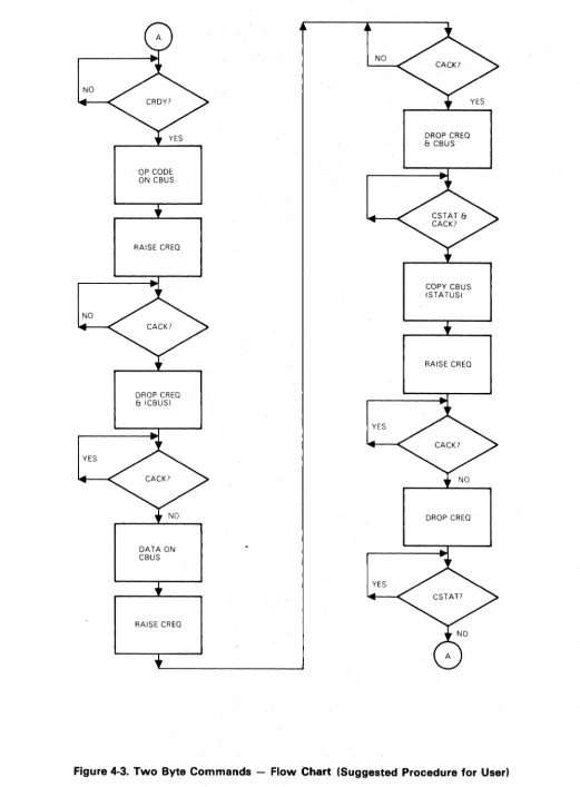
Two Byte Commands - Flow Chart
(Suggested Procedure for User) ... 4-6
Two Byte Commands - Timing B-1
Diagram ... 4-7
TABLES
Page TABLE.
Disk Drive Specifications ... 2-1 Control Signals ... 3-1 Read/Write Signals ... 3-2 Number of Sectors Per Track* ... 5-2 Net Capacity (20 Megabytes)* ... 5-2 Electrical Characteristics ... 6-1 Interface Pin Numbers ... 6-2 DC Cable Pin Numbers (W / a Power
Supply Option) ... 6-2 AC Cable Pin Numbers (W/O Power
Supply Option) ... 6-2
7-1 7-2 A-1 A-2 A-3 A-4 Page
Media Initialization ... 4-7 Non-Imbedded ID Field Read Timing .... 4-8 Imbedded ID Field Read Timing ... 4-8 Non-Imbedded ID Field Write Timing .... 4-9 Imbedded ID Field Write Timing ... 4-9
Sector Formats ... 5-1
Connector Locations ... 6-2
Basic Drive Dimensions ... 10-1
Customer Designed PCB Physical
Requirements ... B-1
Page
Number of Sector Switches ... 7-1 Write Protect Switches ... 7-1
Interface Pin Assignments - Bus ... A-l
Interface Pin Assignments - Signal .... A-l
Interface Pin Assignments - Data ... A-2
SECTION 1 INTRODUCTION
1.1 PURPOSE
This manual contains information necessary to interface a MARKSMAN disk drive to a controller and ultimately to a computer system and provides the technical specifications for reference in OEM contracts.
1.2 RELATED DOCUMENTS
Companion documents on MARKSMAN that are avail-able include:
MARKSMAN Technical Manual T-2004 Exerciser Technical Manual
1.3 GENERAL DESCRIPTION
P / N 76220- 1 00 PIN 76221-100
MARKSMAN represents a breakthrough in cost-perfor-mance ratio for rigid disk drives. With a marriage of fourth generation technology for high performance and floppy disk techniques for maximum economy, it offers the best of two worlds.
Data integrity comparable to that found in . large disk systems is assured by the use of Winchester style heads and media. System reliability is maximized by the sealed contamination controlled disk compartment and the reduction in the parts count achieved by the use of a microprocessor.
The economy is achieved by the use of a band posi-tioner driven by a stepper motor. The microprocessor controls this motor, allowing it to slew at high speeds, thus creating significant improvements in stepper motor performance.
MARKSMAN is designed to enable the OEM systems manufacturer to achieve a high degree of flexibility and the largest practical percentage of added value in the
memory subsystem. The drive electronics include all of the analog functions, and those digital functions that are intimately related to the mechanics such as the stepper motor slew control and fault monitoring. The interface to the drive is by direct connection to the microprocessor Parallel Interface Adaptor (PIA).
• 10MB or 20MB of low cost, high performance
storage.
• Winchester Technology Heads and Media provide state-of-the-art performance.
• High speed Start/Stop and landing zones maximize
head/media life.
• Single/ Board Microprocessor Based Electronics
provide flexibility and simplify maintenance.
• Microlnterface optimizes the microprocessor based
controller interface.
• Compatible with Floppy Disk power supplies ..
• Data Transfer Rate Improvement of 15: 1 over
double density floppy disks.
• Access Time Improved Over 100%, to 12 times the data as compared to floppy disks.
• VFO Data Separator standard.
• No Preventive Maintenance required.
• Provision for Mounting embedded customer
SECTION 2 SPECIFICATIONS
2.1 OPERATIONAL SPECIFICATIONS
2.1.1
Operational specifications for MARKSMAN 10m and 20m Disk Drives are listed in Table 2-1 below.
Table
2-1.
Disk Drive SpecificationsMODEL
Bytes per track Tracks per cylinder Bytes per cylinder Number of cylinders . Bytes per drive
Single track positioning time Average positioning time Maximum positioning time Head Settling time 1 Rotationaf speed (nominal) Average latency time Recording density Track density I/O Transfer rate
Bit Cell time Recording code Interface code (data) Positioning method
Start time (nominal) Write-To-Read Delay Read-T a-Write Delay
M-10 M-20
24000 24000
2
4
48000
96000
210 210
10.08M 20.16M
3 milliseconds 43 milliseconds 113 milliseconds 17 milliseconds 2400 RPM 12.5 milliseconds 7545 BPI
182 TPI
960 Kilobytes/second (7.68 Megahertz) 130 nanoseconds MFM
NRZ Serial
Stepper motor-driven band positioner 3 minutes 161lsec 100nsec .~
1 Add settling time to positioning time to obtain data access time.
2.2 RELIABILITY
2.2.1 Mean Time Between Failures
MTBF is defined by the expression:
MTBF
=
Operating Hrs.No. of Equipment Failures
Operating hours relate to the total "AC Power On" hours less any maintenance time. Equipment failures are defined as those failures requiring repairs, adjust-ments or replaceadjust-ments on an unscheduled basis, i.e., emergency maintenance required because of hardware
failure or substandard performance due to operator error, adverse environment, power failure, controller failure, cable failure or other failures not caused by the drive.
The basic MARKSMAN has a designed MTBF of 8000 hours. The sealed mechanism alone has a designed MTBF of 25,000 hours.
To establish a meaningful MTBF, operating hours must be greater than 20,000 hours and include all sites where the drives are used.
2.2.2 Mean Time To Repair
MTTR is defined as the time for an adequately trained and competent serviceman to diagnose and correct a malfunction at the subassembly level. MARKSMAN is designed so that the MTTR is expected to be less than 0.5 manhours. The sealed portion of the drive is not field repairable and must be returned to the factory for repair in a special clean room environment.
2.2.3 Preventive Maintenance Time
No preventive maintenance is required.
2.3 DATA INTEGRITY
2.3.1 Recoverable Errors
A recoverable error is one which may be corrected by
no more than 5 attempts to read the record. Any com-bination of seek-write, seek-read, seek-rezero is allowed without limitation of combination or duty cycle. Data patterns and track position do not affect data error rate performance. The recoverable read error rate for
MARKSMAN Is less than one error in 1010 bits read.
2.3.2 Non-Recoverable Errors
The non-recoverable error rate for MARKSMAN is less than one error in 1013 bits read.
2.3.3 Positioning Errors
The positioning error rate is less than one error in 106
seek executions.
2.3.4 Media
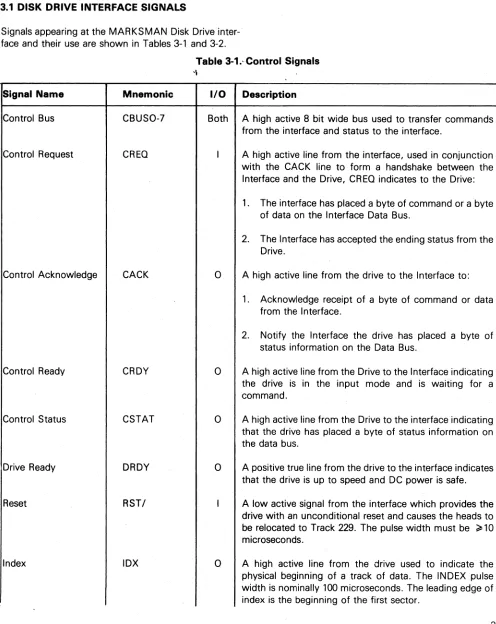
3.1 DISK DRIVE INTERFACE SIGNALS
SECTION 3 INTERFACE SIGNALS
Signals appearing at the MARKSMAN Disk Drive inter-face and their use are shown in Tables 3-1 and 3-2.
Table 3-1.' Control Signals '\
Signal Name Mnemonic I/O Description
Control Bus CBUSO-7 Both A high active 8 bit wide bus used to transfer commands
from the interface and status to the interface.
Control Request CREO I A high active line from the interface, used in conjunction
with the CACK line to form a handshake between the Interface and the Drive, CREO indicates to the Drive:
1. The interface has placed a byte of command or a byte of data on the Interface Data Bus.
2. The Interface has accepted the ending status from the Drive.
Control Acknowledge CACK
0
A high active line from the drive to the Interface to:1. Acknowledge receipt of a byte of command or data from the Interface.
2. Notify the Interface the drive has placed a byte of
status information on the Data Bus.
Control Ready CRDY
0
A high active line from the Drive to the Interface indicatingthe drive is in the input mode and is waiting for a command.
Control Status CSTAT
0
A high active line from the Drive to the interface indicatingthat the drive has placed a byte of status information on the data bus.
Drive Ready DRDY
0
A positive true line from the drive to the interface indicatesthat the drive is up to speed and DC power is safe.
Reset RST/ I A low active signal from the interface which provides the
drive with an unconditional reset and causes the heads to
be relocated to Track 229. The pulse width must be ~10
microseconds.
Index lOX
0
A high active line from the drive used to indicate the [image:10.612.62.558.130.754.2]Signal Name
Sector
Write Unsafe
,Signal Name
Write Data
Write Clock
Write Gate
Read Data
Read Clock
Read Gate
MPU Clock
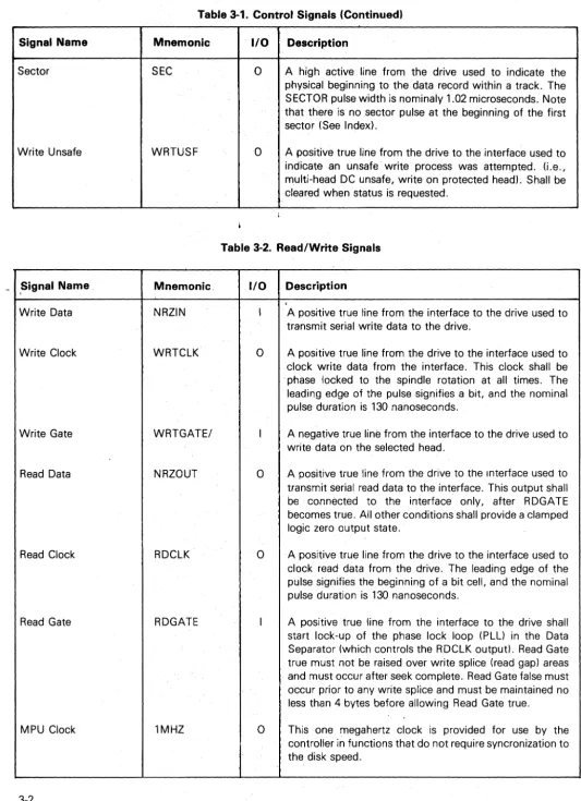
Table 3-1. Control Signals (Continued)
Mnemonic SEC WRTUSF Mnemonic. NRZIN WRTCLK WRTGATEI NRZOUT RDCLK RDGATE 1MHZ
1/0 Description
0
A high active line from the drive used to indicate thephysical beginning to the data record within a track. The SECTOR pulse width is nominaly 1.02 microseconds .. Note that there is no sector pulse at the beginning of the first sector (See Index).
0
A positive true line from the drive to the interface used toindicate an unsafe write process was attempted. (j.e., multi-head DC unsafe, write on protected head). Shall be cleared when status is requested.
Table 3-2. ReadlWrite Signals
1/0 Description
I A positive true line from the interface to the drive used to
transmit serial write data to the drive.
o
A positive true line from the drive to the interface used toclock write data from the interface. This clock shall be phase locked to the spindle rotation at all times. The leading edge of the pulse signifies a bit, and the nominal pulse duration is 130 nanoseconds.
I A negative true line from the interface to the drive used to
write data on the selected head.
o
A positive true line from the drive to the Interface used totransmit serial read data to the interface. This output shall be connected to the interface only, after R DGA TE becomes true. All other conditions shall provide a clamped logic zero output state.
o
A positive true line from the drive to the interface used toclock read data from the drive. The leading edge of the pulse signifies the beginning of a bit cell, and the nominal pulse duration is 130 nanoseconds.
I A positive true line from the interface to the drive shall
start lock-up of the phase lock loop (PLL) in the Data Separator (which controls the RDCLK output). Read Gate true must not be raised over write splice (read gap) areas and must occur after seek complete. Read Gate false must occur prior to any write splice and must be maintained no less than 4 bytes before allowing Read Gate true.
o
This one megahertz clock is provided for use by the [image:11.629.28.562.42.777.2]SECTION 4
INTERFACE DESCRIPTION
4.1 GENERAL
The controller interface functions may be divided into four areas:
• Single Byte Commands (SEQUENCE, REZERO,
STATUS, REQUEST, HEAD ADVANCE)
• Two Byte Commands (SEEK, SET SECTOR,
DI-AGNOSE)
• Data Transfer (READ & WRITE operations)
• Drive Malfunctions and Controller Errors
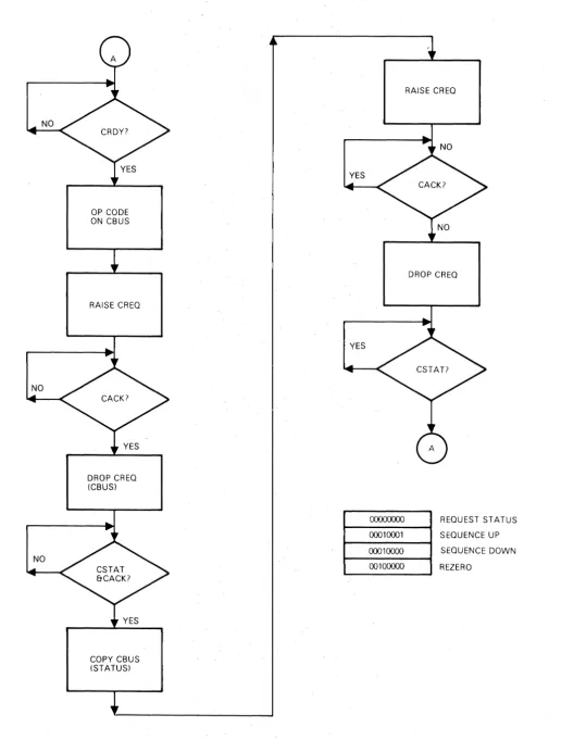
4.2 ONE BYTE COMMANDS (Figure 4-1, 4-1A, 4-2
& 4-2A)
4.2.1 Sequence
7 6 5 4 3 2
o
o o
o
o o o
x
Bit 0 .;
cr
Sequence UpBit 0
=
1 Sequence DownThe SEQUENCE command causes the disk drive motor
to power up (Bit 0
=
0) or power down (Bit 0=
1l.During a power up, the speed of the disk is checked and when speed is within tolerance, the heads are posi-tioned to cylinder zero, head zero. DRDY and CRDY are
both held inactive for 3 minutes. During a power down,
the heads are positioned to the landing zone before power is removed from the drive motor. A sequence UP command must be used to bring the drive up to speed and ready. If power fails, the heads land where they are.
4.2.2 Rezero
7 6 5 4 3 2
o
o o
o o o o o
The rezero command causes the heads to be reposi-tioned to cylinder zero, head zero.
4.2.3 Status Request
7 6
5
4 3 2 1 0o
o o o o
X
X
X
xxx
000 001 010 011 100 101 110 111 StatusExpanded Status
Last Command (MSB - 1st or only byte)
Last Command (LS B - 2nd byte on 2 byte
commands)
CAR (Current Cylinder) Sector Per Track Diagnostic Bits (TBD) Diagnostic Bits (TBD)
Status Bit Significance
Bit 0
1
Track zero: heads are located over track zero. Landing zone: heads are located over landing zone.
2 Illegal Command (Set if any of bits 2,4,5,6, or
7 of expanded status set.)
3 4 5 6
7
Ready: the disk is up to rotational speed. Spin acceleration/deceleration out of limit.
End of cylinder (Head 3 is selected)
Diagnostic error Track zero error
Expanded Status Bit Significance
Bit 0 Sector Length
1 Switches
2 Illegal Set Sector
3 Sector Per Track set by
o
=
Sector Length Switches1
=
Set Sector Command4 Illegal Rezero or Illegal Seek
(Drive not up to speed or Seek attempted from landing zone)
5 Illegal Cylinder
6 Illegal Command
7 Attempted Write on
On a Write Protected Head
The Status Request command causes the current status of the drive to be returned to the interface. Status bits are cleared after being presented to user except for bits 0, 1, 3 and 5. Expanded status bits are cleared after a
specific request for expanded status except bits 0, 1, 3
NO
NO
NO
OP CODE ON CBUS
RAISE CREQ
DROP CREQ (CBUS)
COPY CBUS (STATUS)
YES
YES
OOOO()(){)()
00010001 0001()(){)() 00100000
RAISE CREQ
DROP CREQ
[image:13.615.45.561.37.718.2]REQUEST ST ATUS SEQUENCE UP SEQUENCE DOWN REZERO
NO
NO
YES
OP CODE ON CBUS
RAISE CREG
DROP CREG
& ICBUS)
WAIT FOR TIME TO ADVANCE HEAD
YES
YES
OPTIONAL WAYS OF ISSUING CREG HEAD ADVANCE PULSES
COPY CBUS (STATUS)
RAISE CREG
DROP CREG
NO
RAISE CREG
DROP CREG
RAISE CREG
DELAY>2"s
DROP CREG
[image:14.612.64.551.44.707.2]... _O_,,_OOO--..;.x_x_--J
1 HEAD ADVANCECRDY
CREO
CACK
CBUS
CSTAT ---~\r---J
,~---_r---~/ '~
____________________
'I---J/
[image:15.624.43.566.24.738.2]COMMAND END STATUS
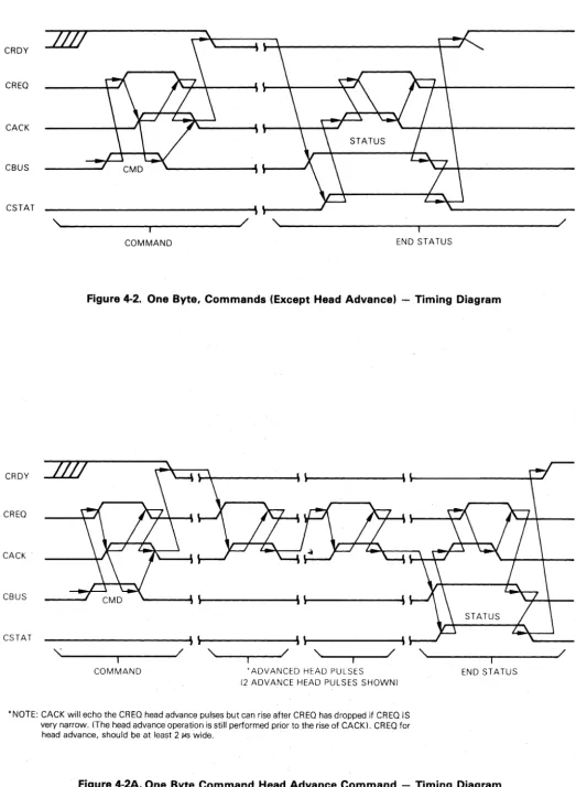
Figure 4-2. One Byte, Commands (Except Head Advance) - Timing Diagram
CRDY
CREO
CACK
CBUS
CSTAT
,~.---~---~/ - I ,~--~~--~/ - I ,~--~----~/ - I ,~---~---~/ - I
COMMAND 'ADVANCED HEAD PULSES END STATUS
12 ADVANCE HEAD PULSES SHOWN)
• NOTE: CACK will echo the CREO head advance pulses but can rise after CREO has dropped if CREO IS very narrow. (The head advance operation is still performed prior to the rise of CACK). CREO for head advance, should be at least 2 /:IS wide.
Figure 4-2A. One Byte Command Head Advance Command - Timing Diagram
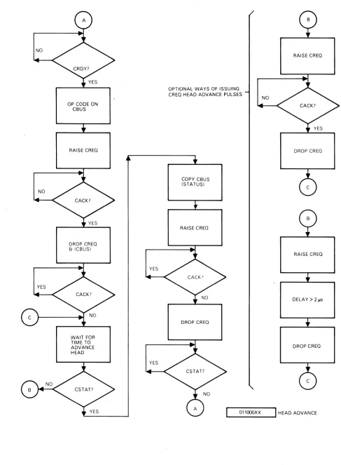
4.2.4 Head Advance
xx
00 01 10 117 6 5
4
3 2o
o o o
NO OP
Advance Head One Time Advance Head Two Times Advance Head Three Times
o
x
x
This command provides a means of advancing the head address more rapidly than can be done using the SEEK COMMAND thereby allowing sequential sector ac-cesses across head boundaries.
The HEAD ADVANCE COMMAND places the drive in a state where it waits for the rise of CREG. The drive ad-vance the head address in about 11
JAs
to 25 I-'S after CREG goes active. During the CREG-CACK handshake, the drive does not copy the CBUS. STATUS is pre-sented when either the commanded head advance count is depleted or the head address is advances to the last head. CRDY will remain inactive (and the drive in-capable of accepting another command) until the STATUS is delivered. The last-head bit (bit 5) in the STATUS word will be active whenever the last head is selected.4.3 TWO BYTE COMMANDS (Figure 4-3 & 4-4)
4.3.1 Seek
7 6 5 4 3 2
o
o
o o o o
H H Cylinder AddressThe SEEK command is used to position the heads over the specified cylinder and select the head addressed by the low order bits of the command byte. The SEEK command requires one Byte transferred with the command to specify the cylinder.
4.3.2 Set Sector
7 6 5 4 3 2
o
o
o
o o o o
Sector Count
This command is used to override the switch setting of S1 and S2 and define the number of sector pulses from 3 to 255.
This selection will remain until another SET SECTOR command is issued or upon re-powering-up, at which time, it will use the switch settings.
4.3.3 Diagnose (Optional)
7 6 5 4 3
2
o
o o o o o o o
o
TEST NUMBERThis command and op code are reserved for future use.
4.4 DATA TRANSFER
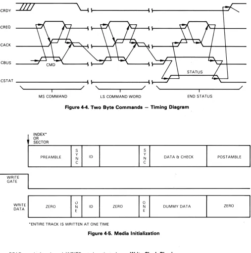
4.4.1 Media Initialization Figure 4-5
New media or media which has had a format change must first be formatted before data can be written onto the disk. Please refer to Section 5 for format require-ments.
The cylinder and track are selected in accordance with the previously mentioned procedure. At INDEX time, WRITE gate is activated and the appropriate data is written.
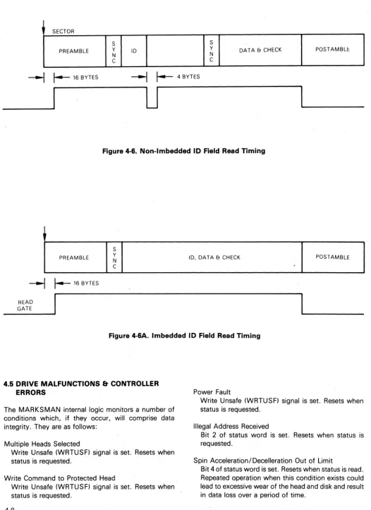
4.4.2 Reading (Figures 4-6, 4-6A)
A.
Non-Imbedded 10 FieldSixteen bytes after the SECTOR pulse, READ gate is activated. Zeros appear on the NRZ data out signal until the PLL is in sync or locked. Imme-diately following the SYNC byte is the ID or header field. At the end of the ID field, READ gate must be deactivated for a four byte time period and reacti-vated. This action enables the read circuitry to
reaquire lock before the SYNC byte.
B. Imbedded 10 Field
The READ gate is activated sixteen bytes after INDEX pulse and deactivated after the data field. READ gate must not be activated until at least 161-'s have passed after WRITE gate is deactivated or the head is selected.
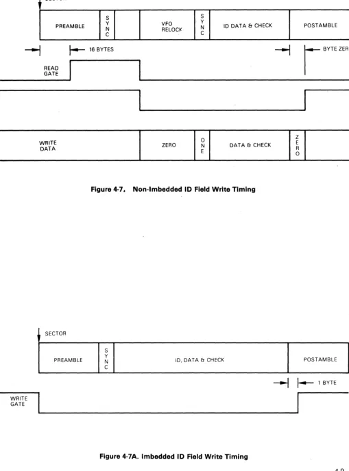
4.4.3 Writing (Figures 4-7, 4-7A)
A. Non-Imbedded 10 Field
4-6
NO
NO
YES
OP CODE ON CBUS
RAISE CREO
DROP CREO
& (CBUS)
DATA ON CBUS
RAISE CREO
NO
YES
YES
DROP CREO
& CBUS
COPY CBUS (STATUS)
RAISE CREO
[image:17.621.44.565.44.750.2]DROP CREO
CRDY
/10
~\
CREO
CACK
CBUS
STATUS
CSTAT
'\ / '\ / '\ /
I I I
[image:18.612.59.566.55.566.2]MS COMMAND LS COMMAND WORD END STATUS
Figure
4-4. Two
Byte Commands- Timing DiagramWRITE GATE
INDEX* OR SECTOR
PREAMBLE
S Y N C
S
ID Y N DATA & CHECK POSTAMBLE
C
~A~~ELI
______ Z_ER_O ____~I
__~-LI
__ I_D __ LI ____ Z_E_R_O ____~I_~_E_~I
____ D_U_M_M __ Y_D_A_T_A ____ -L ______ Z_ER_O ____~
*ENTIRE TRACK IS WRITTEN AT ONE "T:IMEFigure 4-5. Media Initialization
READ gate is deactivated, WRITE gate is activated, and the appropriate data is written. WRITE gate is deactivated one byte into the postamble.
B.
Imbedded ID FieldThe WRITE gate is activated at SECTOR pulse time and deactivated one byte into the postamble.
4.4.4 Read Clock Phasing
The positive going transition of read clock should be used as the data strobe.
Write Clock Phasing
Since the MARKSMAN provides the write clock, the data/clock phase relationship is a function of the cable length and internal controller delays. This relationship,
measured at the disk drive, should have the positive
transition of the internal capture clock, Chip A46, pin 11,occuring nearest the center of the NRZ data, Chip A46, pin 12. Should this not be true, the connection between Test Points E20 and E21 should be broken and E20 and E22 established. *
SECTOR
S S
PREAMBLE Y ID Y DATA & CHECK POSTAMBLE
N N
C C
~
~
16 BYTES---1
~
4 BYTES [image:19.620.36.563.36.760.2]__
~---'U
Figure 4-6. Non-Imbedded 10 Field Read Timing
PREAMBLE
~
~
16 BYTESHEAD GATE
S
Y
N
C
ID. DATA & CHECK POSTAMBLE
,
Figure 4-6A. Imbedded 10 Field Read Timing
4.5 DRIVE MALFUNCTIONS & CONTROLLER
ERRORS
The MARKSMAN internal logic monitors a number of conditions which, if they occur, will comprise data integrity. They are as follows:
Multiple Heads Selected
Write Unsafe (WRTUSFI signal is set. Resets when status is requested.
Write Command to Protected Head
Write Unsafe (WRTUSFI signal is set. Resetswhen status is requested.
Power Fault
Write Unsafe (WRTUSFI signal is set. Resets when status is requested.
Illegal Address Received
Bit 2 of status word is set. Resets when status is requested.
Spin Acceleration/Decelleration Out of Limit
WRITE GATE
SECTOR
S S
Y VFO Y 10 DATA & CHECK
PREAMBLE N
RELOCI< N
C C
~ 16 BYTES READ
GATE
WRITE DATA
SECTOR
PREAMBLE
ZERO DATA & CHECK
Figure 4-7. Non-Imbedded 10 Field Write Timing
S Y
N 10, DATA & CHECK
C
Figure 4-7A. Imbedded 10 Field Write Timing
POSTAMBLE
I
BYTE ZEROI
!
I
POSTAMBLE
~
r
1 BYTEI
[image:20.618.56.565.60.748.2]SECTION 5
FORMAT REQUIREMENTS
5.1 GENERAL
In order to guarantee operations over the entire temp-erature range, allow for component tolerances and compensate for cable and controller delays, all disk drives must have a preamble and postamble attached to each sector. The amount of overhead is a function of the electrical and mechanical tolerances and the bit transfer rate as well as the system requirements. The preamble and postamble contain all ZEROS.
S
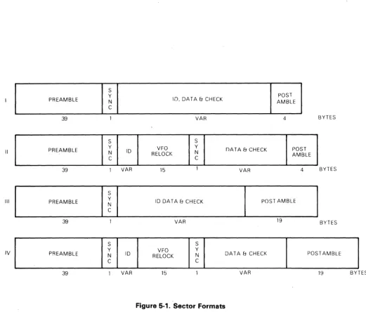
5.2 FORMAT DEFINITIONS
Four different formats have been sug.gested for MARKSMAN. They are illustrated in Figure 5-1.
Format I requires the least amount of overhead. Format II is similar, but separates the header (10) field from the data, allowing the data to be updated without rewriting the header. They are both designed for sequential operation, however, with either of the above formats, it
Y POST
PREAMBLE N ID, DATA & CHECK AMBLE
C
39 VAR 4 BYTES
S S
II Y VFO
Y
IJA T A & CHECK POST
PREAMBLE N ID
RELOCI< N AMBLE
C C
39 VAR 15 VAR 4 BYTES
S
III PREAMBLE Y ID DATA & CHECK POST AMBLE
N
C
39 VAR 19 BYTES
S S
IV PREAMBLE Y N ID RELOCK VFO Y N DATA & CHECK POST AMBLE
C C
[image:21.618.47.569.300.744.2]39 VAR 15 VAR 19 BYTES
is possible to miss the succeeding sector when
a
head advanced command is issued. Should this be undesir-able, Formats II and IV have a larger postamble to insure that after a head advanced command is issued the suc-ceeding sector is not missed.5.3 SECTOR CALCULATIONS
The following formula is used to calculate the number of sectors for any given sector size. Table 5-1 and 5-2.
24000 N
=
INT DATA+
ID+
OHWHERE: INT (Number) - Greater Integer Contained Within Number
N Data ID OH
number of sectors (whole integer) length of data field plus check characters length of header
Length of overhead field
44 for Format I 60 for Format II 59 for Format III 75 for Format IV
. 24000
The first N-1 sectors are of length
=
INT (---rT1) bytes.The last sector is of length
=
24000 - [(N -1) INT¥
I], Whenever it is necessary to change at the end of a track and continue operation without lOSing a revolution, and end-of-track pad, which accommodates the command execution and head switching, must be provided.The command sequence for a no-motion seek takes over 500 /-'S (500 bytes) to complete, measured from the initial rise of CREO to the rise of CRDY after end status. (The actual time depends on the controller's contribution to sequence delays). The target head is selected no earlier than 300 /-'s (300 bytes) after the in-itial rise of CREO. The end-of-track pad for seek is, therefore, very large.
The use of the HEAD ADVANCE command sequence yields selection of the target head 11 /-'S to 25 /-'S after CREO rises. READ gate must be delayed 16 /AS after
[image:22.615.41.578.71.735.2]head selection, but does not occur (in the specified for-mats) until 16 bytes (16 /-,s) after the sector pulse, hence, the head-advancing CREO must rise no later than 25 /-'S before the sector pulse. It may rise as early as 11 /-'S (10 bytes at low disk speed) before the end of the last data to be read. The minimum end-of-track pad for head advance is, therefore, 15 bytes. The raw sector length calculation above shows that most sector for-mats provide some inherent pad in the last sector.
Table 5-1. Number of Sectors Per Track
Format
Sector Size I II III IV
128 Bytes 129 119 119 111
256 Bytes 76 72 72 69
512 Bytes 42 41 41 40
1024 Bytes 22 21 21 21
Assuming an 8 byte ID field and a 5 byte check character.
Table 5-2. Net Capacity (20 Megabytes)*
Format
Sector Size I II III IV
128 Bytes 13.87 12.79 12.79 11.93 256 Bytes 16.34 15.48 15.48 14.84 512 Bytes 18.06 17.63 17.63 17.20 1024 Bytes 18.92 18.06 18.06 18.06
*(M-10 capacity is one half of that shown)
5.4 SECTOR SELECTION
The Sector Length switches (described in Section 7) determine the number of sector pulses that occur with-out the use of the SET SECTOR command. They select either 111, 69, 40, or 21 sectors per track. Ref. to
SECTION 6 SIGNAL LEVELS
6.1 CBUSO-7. CREQ. CACK
These signals interface directly to the Motorola MC6821 Peripheral Interface Adaptor (PIAl.
Electrical Characteristics (V CC
=
5.0V + 5%, V SS=
0,TA=TLtoTH
unless otherwise noted)
6.2 ALL OTHER SIGNALS
All other signals interface to 74LSXXX Logic. Refer to the IC manufacturer's literature for drive capability.
6.3 MATING CONNECTORS
Interface 3M
#
3432-2002 or Cannon#
UND4B04OD3DDC Power Molex 1292-9R with 1189 sockets AC Power Molex 1991-4R with 1189 sockets
6.4 CABLE LENGTH
[image:23.613.64.568.418.716.2]The drive is supplied with a four inch cable. The con-troller logic must be placed in close proximity to this cable. If additional cable length is required, the Driver/ Receiver Option described in Appendix A or equivalent must be used.
Table 6-1. Electrical Characteristics
Characteristics Symbol Min Typ Max Unit
Input Leakage Current CRQ lin
-
1.0 2.5 Adc(Vin = 0 to 5.25 Vdc)
Input High Current CBUSO-7 IIH -200
-400
-
Adc(VIH = 2.4 Vdc) CACK
Input Low C<.lrrent CACK IlL
-
1.3 -2.4 mAde(VIL = 0.4 Vdc)
Output High Voltage CBUSO-7 VOH
(lioad = - 200 ,., Adc) CACK VSS +2.4
-
-
Vdc(lioad = -10,., Add VCC -1.0
-
...,..Output Low Voltage VOL
-
0 VSS +0.4 Vdc(lioad = 3.2 MAdc)
Capacitance Cin
-
-
10 pFT"~!~ fi-2. Inlerf~ce Pin Numbers Table 6-3. DC Cable Pin Numbers
J1-1 CACK J1-21 SEC
(W/O Power Supply O~tiqn)
2 RSTI 22 GRD J2-1 +5V J2-6 SPARE
3 CBUSO 23 CSTAT 2 GRD 7 +24V
4 CBUS1 24 GRD 3 -12V 8 + 24V Stepper
5 SPARE 25 WRTCLK Ground
4 + 12 (Output)
6 CREQ 26 GRD 5 GRD 9 SPARE
7 GRD 27 NRZIN
8 CBUS2 28 GRD
9.
CBU~~ 29 RDCLK10 CBUS7 30 GRD Table 6-4. AC Cable Pin Numbers
11 C!3US5 31 NRSOUT (W/O Pqwer Supply Option)
12
CBUS3 32 GRD J3-1 AC High13 SPARE 33 WRTGA 2 AC Common
14 IPX 34 GRD 3 Chassis Ground
15 GRD 35 RDGATE 4 Spare
16 DRDY 36 SPARE
17 CRDy 37 SPARE
18 GAD 38 SPARE
19 1MHZ 39 WRTUSF
20 GRD 40 CBUS4
INTERFACE AC
CONN.
Figure 6-1. Connector Locations
[image:24.627.55.552.47.739.2]SECTON 7
CONTROLS AND INDICATORS
7.1 GENERAL Table 7-'2. Write Protect Switches
Front Panel None
Rear Panel None
Internal
Location S-1 on the Basic Control PCB (Sector Length and Write Protect Switches). Tables 7-1 and 7-2.
Table 7-1. Number of Sector Switches
Number Sector Length
Switch S2 of (using Format IV)
-1 -2 Sectors
Closed Closed 111 128 Bytes
Closed Open 69 256 Bytes
Open Closed 40 512 Bytes
Open Open 21 1024 Bytes
Switch S1
-3
-4 -5 -6Closed
-
-
--
Closed-
--
-
Closed--
-
ClosedProtected Head Number
1 2
3
[image:25.617.60.566.181.769.2]SECTION 8
ENVIRONMENTAL CHARACTERISTICS
8.1 TEMPERATURE (with or without optional enclosure)·
Equipment: Operational:
Equipment
Non-50°F to 104°F (10°C to 40°C) with a max. gradient of 18°F (100C) per hour.
Operational: -40°F to 140°F (-40°C to 60°C)
Temperature
Cycling: No condensation shall result.
·without enclosure, 200 feet/minute air velocity must be maintained over the base casting.
8.2 HUMIDITY (with or without optional enclosure)
Equipr:nent Operational:
Equipment non-Operational:
10% to 90% R.H., with a wet bulb temp. limit of 80°F (27°C) (provided there is no condensation.)
5% to 95% R.H., provided there is no condensation.
8.3 ALTITUDE (without optional enclosure)
Equipment
Operational: From 1000 feet below sea level to
6000 feet above sea level .. Optional kit to 10,000 feet.
8.4 VIBRATION (with optional enclosure)
Equipment Operational:
Equipment Non-Operational:
8.5 SHOCK
The equipment shall withstand a peak displacement of ±0.006 in. ('015 cm) for the frequency range of 20 Hz to 40 Hz and ± 19 for the 40 Hz to 200 Hz range.
The equipment when packed for shipment shall withstand ± 1.5g from 5 Hz to 55 Hz for one hour along each of the three mutually perpendicular axes, with a 20 minute sweep time.
The equipment shall perform all read/write operations (no seek) according to specifications, while being sub-jected to 18 impact shocks of 3g (± 10%) consisting of 3 shocks along each direction of three mutually perpen-dicular axes. Each shock impulse shall be half sine wave with a time duration of 11 (± 1) msec.
SECTION 9
POWER REQUIREMENTS
9.1 BASIC DRIVE
9.1.1 AC Power
1001115V (+10%, -15%),50/60 Hz (±1 Hz) Running: 1.5A
Starting: 11.0A
220/240V (+10%, -15%),50/60 Hz (±1 Hz)
Running: O.SA '
Starting: 5.5A
9.1.2 DC Power
+ 24V, ±5%, 2.7A*
-12V, ±5%,0.3A**
+5V, ±5%, 2.5A**
*Tolerance includes ripple less than 10 KHz. Greater than 10 KHz ripple should be less than 0.5%.
*-Ripple must be less than +0.5% from'10 Hz toKHz.
9.2 POWER SUPPLY AND DRIVE
9.2.1 AC Power
1001115 (+10%, -15%) 60 Hz (±1 Hz) Running: 3.5A
Starting: 13.0A
200/220/240V (+ 10%, -15%) 50 Hz (± 1 Hz) Running: 2A
SECTION 10
PHYSICAL CHARACTERISTICS
10.1 PHYSICAL SIZE 10.2 MOUNTING ATTITUDES
Basic Drive Enclosure Option Horizontal - spindle pully down
Height 8.62" (219 mm) 8 %" (222 mm) Vertical - unit on side motor on top Width 16.24" (412 mm) 17 W' (445 mm)
Depth 23.88" (607 mm) 27 y." (690 mm) Weight 451bs. (20.0 kg) 85 Ibs· (43.0 kg)
·110Ibs. (50 kg) with power supply option
r----.
24.73162.811I
.
[ - - 1 6 . 9 4 0 1 4 3 . 0 2 8 1 - - - l ..--t\
'----~~---+--I-
- - -
--15.000
138.1001
+
2.312
L
1133401 5.252-J
~----+---i1~1
10472 126 4 0 1 - - - - t
[ 1.00 CLEARANCE RE~ PC BOARD MOUNT
DISK
SHOCK MOUNT
Figure 10-1 Basic Drive Dimensions
16.554 142.051 MIN
i t
8.50 [image:28.617.61.558.72.782.2]APPENDIX A
DRIVER/RECEIVER OPTION
GENERAL Table A-2. Interface Pin Assignments - Signal
The MARKSMAN Driver/Receiver Feature increases the allowable interface cable length of the MARKSMAN from 4 inches to 50 feet. It also provides the means by which drives may be daisy chained.
INTERFACE
[image:29.615.65.566.234.777.2]Refer to Tables A-1 through A-4 for interface pin assignments.
Table A-1. Interface Pin Assignments - Bus
J1- J2- Serial Name Source Ckt Dest Ckt
1 1 GRD
2 2 ICSUS 61 75462 74LS240 3 3 ICSUS 51 75462 74LS240 4 4 ICSUS 71 75462 74LS240 5 5 ICSUS 21 75462 74LS240 6 6 ICSUS 41 75462 74LS240 7 7 ICSUS 01 75462 74LS240 8 8 ICSUS 31 75462 74LS240 9 9 ICSUS 1 I 75462 74LS240 10 10 GRD
11 11 GRD
12 12 IRSTI 74S367
13 13 GRD 14 14 SPARE
J1- J2- Serial Name So",rce Ckt Dest Ckt
15 15 GRD
16 16 IRDGATEI 74S367
17 17 GRD
18 18 IWRGATEI 74S367
19 19 GRD
20 20 ICREQI 74S367
21 21 GRD
22 22 IDRDY
I
75462 23 23 GRD24 24 ICRDY
I
75462 25 25 GRD26 26 IWRTSUFI 75462 27 27 GRD
28 28 ICACKI 75462 29 29 GRD
30 30 ISECI 75462 31 31 GRD
32 32
IIDXI
7456233 33 GRD
34 34 ICSTATI 75462 35 35 GRD
36 36 TERMIN 37 37
Table A-3. Interface Pin Assignments - Data Table A-4. DC Pin Assignments
.-J3\"
Serial Name Source Ckt Dest Ckt J6- Serial Name1 GRD
2 GRD --,
-1 +5V
3 IWDATAP
••
-2 GRD4 IWDATAM
••
5 GRD
-3 -12V -4 +12V -5 GRD
6 ISELECT 74LS132,
7 GRD
8 IRDATAM
•
9 IRDATAP
•
10 GRD
11 IRDCLKM
•
12 IRDCLKP _•
13 GRD14 IWRTCLKM
•
15 IWRTCLKP•
16 GRD17 RCRDY 75462
18 +5V 19 +5V
20 RSECI 75462
21
RIDXI
7546222 RSEL~CTEDI 75462
23
24 25
26 GRD
[image:30.617.47.565.37.746.2] [image:30.617.36.563.61.763.2]APPENDIX B
Customer Designed Printed Circuit Board
Customer designed PCB's should meet the specifica-tions in figure B-1. Since the T -2004 exerciser receives its power from the same cable which feeds this PCB, the power connector location and pin numbers (Figure 6-1) must be located as on the drawing.
The-MARKS-MAN optional enclosure expects the I/O cables to exit
from the locations shown for the 40 pin and 60 pin con-nectors. If this enclosure is not used, these connectors may be relocated.
--11 __ - .062 GAP
400
5875,...
10 312
(2) ~~DIA HOLE
~-_f~---l1W---~~--4~
r,
f1II II I I II
LJ LJ
12 Pl POWER
CONNECTOR LOCATION DISC
40 PIN MALE FLAT CABLE
~~~6~E~~?11 ON t
--'---- :£
~---9~---~
1 o - . - - - 1 1 . 0 0 0 - - - t
1 0 - . - - - -11 .00
---_-1
~~I
___ t _________ _
GND TO MOUNTING FRAME, 440 STUD FLAT CABLE ASS'Y
~1·g6~~~TED ON t=
PWB DL GND
4·40 STUD 12 PU
r-Io:
4.461
15500 TYP
o
~~B9~~~11~~t2Hl.E~L~~~:RU~~~o~t6~ CAPTIVE HARDWARE PIN 95496-003 GROMMET. CLEARANCE HOLE IN MOUNTING FRAME SHALL BE 316·323 IN DIAREF.DWG 2H51 001
(3) MOUNTING PAD AREAS, FARS!DE. TYP 8 PLACES
0) ~6~~~ 0~~E~~E~~~~:~~S~1~~~~iF~~D 0 C. GROUND ONLY,
Figure B-1. Customer Designed PCB Physical Requirements
16.00
[image:31.620.56.561.265.683.2]0
MANUAL TITLETECHNICAL MANUAL CHANGE
MARKSMAN PERFORMANCE SPECIFICATION
Century
Data Systems
._-
PART NUMSER DATE CHANGE NO.76220-902
Mav
15.
1979 ISHEETS: AUT~TION ~ .flj).
J
ofl- C.
'T1.
On
page
4-5,
add the paragraph
4.2.5
which
is
attached.
2.
On
page
4-5,
delete the paragraph
4.3.3.
4.2.5
DIAGNOSE (Optional)
7
6
4
"
. 2
1
o
1
o
o
o
x
X X
X
Where XXXXis the diagnostic test number.
Status is returned in extended status bytes 6 and 7.
Test
~
1
2
o
RAM Test stores 55 16 in all RAM locations and checks contents of aU
locations.
Stores AA 16 in all locations and checks contents of all
locations. Stores incrementing pattern in successive locations and checks
contents of all locations. EXits with status bytes clear if OK.
If
bad,
exits with diagnostic error flag set in status byte
~,address of bad RAM
location in extended status byte 6 and bit pattern of bad location in byte
7.
Rea! Time Clock Test - checks real time clock timeouts against
programmed timeouts. Exits with status bytes clear
if.
OK. If bad, exits
with diagnostic error flag set in status byte
.~and appropriate bits set in
extended status byte 6 as foHows: bit 4
=
timeout; bit 5
=
unsolicited; bit
6 :: interrupt; bit 7.
=
error. Status word 7 is always clear.
Track Zero Test -
checks track at which track zero flag resets while
stepping in and the track at which the flag sets while stepping
out~Exits
with extended status byte 6 containing track number at which track zero
flag reset; status byte 7 contains track number at which it is set.
If
bad,
diagnostic error bit is set in status byte 0 contains track number at which
it is set.
If
bad, diagnostic error bit is set in status byte
~and extended
status bytes 6 and 7 contain FF 16'
Disk Speed Test - measures time between index pulses with real time
Clock. Exits with MSB of speed in status byte 6 and LSB in status byte 7.
If
bad, exits with diagnostic error bit set.
Read RAM - The. contents of RAM are sequentially output to the user
5
6
7
8
ROM Test - builds a checksum for each 256 bytes of program PROM and
compares it to a checksum table. Exits with status bytes clear if OK. If
bad, diagnostic error bit is set and upper address of bad block is in
extended status byte 6 and lower address is in byte 7.
MPU Test -
a non-exhaustive MPU exercise which checks stack
manipulation, addressing modes, interrupt and sub-routine linkage. Exits
with the status bytes clear if OK. H bad, (although it is unlikely you will
get this far) the diagnostic error bit is set and the condition code is
returned in diagnostic status byte 6. Status byte 7 is clear.
Handshake Test - This is a two-byte command. The second byte will be
echoed to the user as status. Normal status will not be presented and the
diagnostic status bytes will not be changed. For effective testing of the
user interface, the following sequence will test all data lines.
0 0 , 01,
'/J2,
'/JlI.,
'/)8,1'/J, 2'/J, 4-'/J, 8'/J, FF, FE, FD, FS, F7, EF, DF, SF, 7F (all in hex).
Seek Test - The seek test will seek from track
0'/J
to track N. N being
track one and incrementing until N equuals track 212. It will verify that
the carriage returns to track zero each time by looking at the track
0'/J
bit.
H test fails, the last track that was successfully restored from N to zero
will be stored in status byte 6. Byte 7 will be cleared and the diagnostic
error bit will be set in status byte
0.
H test passes, status byte 6 and 7
and the diagnostic error bit in status byte
0
will all be cleared.
On power up or reset, the following diagnostic tests will be performed
automatically:
RAM Test
ROM Test
MPU Test
On sequence up, the following diagnostic tests will be performed
automatically:
Real Time Clock Test
Seek Test
If