© 2016, IRJET | Impact Factor value: 4.45 | ISO 9001:2008 Certified Journal | Page 649
DESIGN OF FOLDED RECTANGULAR PATCH ANTENNA WITH
DIFFERENT MULTIDIELECTRIC LAYER
NIKISHA.A.K
1, Dr.K.JAYANTHI
21
PG SCHOLAR, ECE
SNS COLLEGE OF TECHNOLOGY, COIMBATORE, TAMILNADU, INDIA
2
ASSOCIATE PROFESSOR,ECE
SNS COLLEGE OF TECHNOLOGY, COIMBATORE, TAMILNADU, INDIA
ABSTRACT: The bandwidth and efficiency of folded rectangular patch antenna can be improved by addition of superstrate layer over the substrate of folded rectangular patch antenna results the multi dielectric layer microstrip folded patch antenna. The superstrate layer act as a part of the folded patch antenna. Design of folded rectangular patch antenna with different multidielectric layer can improves the gain and antenna efficiency of the antenna. With right choice of the thickness of substrate and superstrate layer, significant increase in gain can be achieved for practical applications. Multidielectric layer microstrip antenna designed for applications where various physical properties of antenna such as permittivity, patch dimensions, height of the substrate and the resonant frequency can be analyzed. The antenna performances can been evaluated for variety of cases of permittivity and thickness of the superstrate layer.
Keywords: Folded rectangular patch antenna, Microstrip Antenna, Multidielectric Layer, Permittivity, Superstrate Layer
1.INTRODUCTION
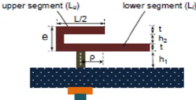
[image:1.595.318.516.303.404.2]The overall length of folded patch antenna is eight times shorter than that of conventional patch antenna. The design which uses air as dielectric reduces the manufacturing cost and enhances fringing area..Wideband high gain antenna can be realised from folded patch antenna. The folded rectangular patch antenna with larger fringing area increases the electrical aperture of radiating patch and produceshigher gain. One of the main drawback of folded patch antenna is that it provides low gain and less bandwidth. When a microstrip folded rectangular patch antenna antenna is covered with a superstrate dielectric layer, its resonant frequency, gain and bandwidth are changed which degrade the system performance. By selecting the thickness of substrate layers , a very large gain can be realized in the design of a microstrip antenna with various multidielectriclayer.
Figure 1.Folded Rectangular Patch Antenna
To reduce the errors an algorithm is used. The algorithm reduces the errors at each step ,providing a result which is highly accurate. The following sections ,the discussions and analysis are
(i) The design of a multidielectric layer folded rectangular patch antenna at 10 GHz.
(ii) Studies on the folded rectangular multidielectric antenna based on the superstrate layer permittivity and thickness.
(iii) Analyzing the performance of the designed folded patch antenna with/without superstrate layer.
2.EFFECT OF CHANGING SUPERSTRATE LAYER
THICKNESS ON THE ANTENNA PARAMETERS
The microstrip antenna is designed to operate at a frequency of 10 GHz. The design of antenna is based on the thickness of the substrate and the superstrate, width and length of the element.2.1 Selection of substrate in the design of the
folded rectangular patch antenna
© 2016, IRJET | Impact Factor value: 4.45 | ISO 9001:2008 Certified Journal | Page 650
A high loss tangent increases the dielectric lossand reduces the antenna efficiency. The substrate parameters so selected are as follows: The upper layer chosen is RT Duroid 5880 of thickness of 0.787mm, and the permittivity of εr = 2.2 and the loss tangent tanδ = 0.0009. The underneath layer dielectric material chosen is RT Duroid 5870 with a thickness of 0.787mm,and permittivity of εr = 2.33 and the loss tangent of tanδ = 0.0012
2.2 Selection of Element width and length of
folded rectangular patch antenna
The selection criteria with patch size of antenna which is not too large are:
(i)A minimum value of the patch width W and (ii) Width and the length should be in good ratio with a good radiation efficiency.The condition needed to be follow is 1<W/L < 2 .The length of upper patch should be half
of
length of lower patch .The patch dimensionsdetermine the resonant frequency. Calculated length and width of the patch obtained is 8.69638mm and 9.6 mm respectively. Effective permittivity is 2.15644, for the net height of the substrate 1.574 mm. So, the calculated Rin which is the value of the patch resistance at the input slot is 326.8508ohms. The condition taken into account, we obtain the values of self conductance G1 and susceptance B1 using equation (1) and (2) respectively
while element as two slots, one at each end of the resonator, the interaction between the two slots is type of mutual conductance. Then, the directivity of a patch is calculated
.
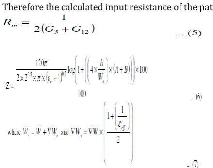
Therefore the calculated input resistance of the patch is
When applying the formula for the impedance matching we get the matching impedance to be Z1=(326.8508*90)^0.5=171.512ohm..The values of the patch length and width are 8.69638 mm and 9.6 mm respectively.
The matching transformer impedance Z2=178.813 ohm and width = 0.26 mm. The patch with width 9.6 mm and length 8.58 mm corresponds to input impedance= 324.0673 ohm. The effective permittivity εeff is equal to 2.15644, the input resistance of the patch is equal to 326.8508 ohm. Impedance of the port used is 90 ohm. Then the impedance parameters are: width=0.26 mm and height=7.25 mm, Feed line impedance=98.3545ohm and width = 1.5 mm, this comes same as the calculated value obtained through the design. The multidielectricfolded patch microstrip antenna designed is to radiate 1.034 mW power, having directivity of 6.77 dB and gain of 5.95 dB achieving the antenna efficiency of 87.88%. Antenna is resonate at the designed frequency of 10 GHz at a return loss of -31.797 dB as shown in Figure
[image:2.595.313.533.107.280.2]1.
© 2016, IRJET | Impact Factor value: 4.45 | ISO 9001:2008 Certified Journal | Page 651
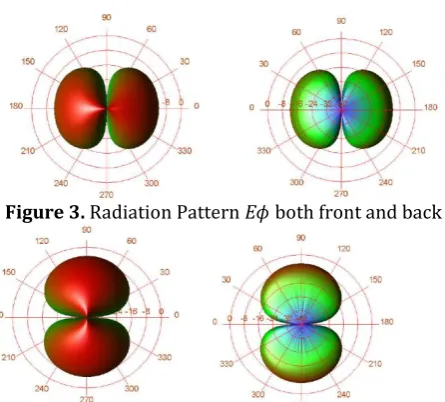
Figure 3. Radiation Pattern Eϕ both front and backFigure 4. Radiation Pattern Eθ both front and back
3. EFFECT OF SUPERSTRATE LAYER
THICKNESS ON THE FOLDED RECTANGULAR
PATCH ANTENNA PARAMETERS
3.1 Superstrates Selection
Superstrates are selected in such a way to compare the effects of its permittivity and its thickness on various parameters of the antenna. The two superstrate selected are Roger’s Corporation are: High Permittivity: RT/Duroid 6010LM have a relative permittivity of 10.2 and a loss tangent of 0.0023. Low Permittivity: RT/Duroid 5880LZ with a relative permittivity of 1.96 and loss tangent of 0.0019. Low and high thickness of the substrate under consideration are 0.254mm and 2.54mm respectively.
3.2 Analysis based on Superstrate Layer
Properties
3.2.1 Case 1
High Permittivity Thick Superstrate has effect on parameters of antenna . Poor gain can be achieved by very low antenna efficiency of the order of 37.65%. For the Case 1, return loss is very poor and at frequency of 8.537 GHz, it
is -3.754 dB as shown in Figure
4
.
Figure 5. Return Loss for High Permittivity Thick Superstrate Antenna
Figure 6. Radiation Pattern Eϕ both front and back
Figure 7. Radiation Pattern Eθ both front and back
From the Figure 5 and Figure 6 it can be concluded that combination of thick superstrate of high relative permittivity result in antenna behavioural pattern
3.2.2 Case 2
[image:3.595.46.269.101.302.2]Antenna parameters in case of Low Permittivity Thick Superstrate shows increase in antenna gain and the efficiency. Return loss at 9.392 GHz is -14.405 dB shows slight improvement as seen in Figure 7. Radiation patterns given in Figure 8 and Figure 9 shows significant improvement ,also radiated power output as compared to Case 1.
[image:3.595.338.539.511.654.2]© 2016, IRJET | Impact Factor value: 4.45 | ISO 9001:2008 Certified Journal | Page 652
Figure 9. Radiation Pattern Eϕ both front and backFigure 10. Radiation Pattern Eθ both front and back
3.2.2 Case 3
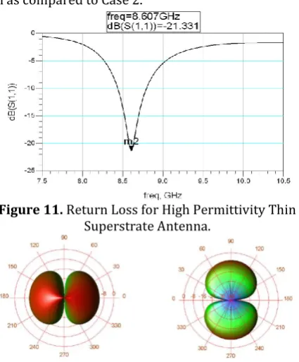
When use the High Permittivity Thin Superstrate , shows a significant improvement in antenna parameters . Return loss of 8.607 GHz is -21.331 dB, gives a good improvement as seen in Figure 10. Radiation pattern shown in Figure 11 and Figure 12,have similar radiation plots as seen in Case 2. Marginal value increase in radiated power output is seen as compared to Case 2.
Figure 11. Return Loss for High Permittivity Thin Superstrate Antenna.
Figure 12. Radiation Pattern Eθ both front and back
Figure 13. Radiation Pattern Eϕ both front and back
3.2.4 Case 4
The use of Low Permittivity Thin Superstrate shows decrease in antenna gain and increase in efficiency. Return loss at the value 9.721 GHz, is -35.041 dB, shows slight improvement and as seen in Figure 13. Figure 14 and Figure 15, gives the radiation plots.For antenna to resonate close to the desired frequency, radiated power is around 1 mW and pattern with no sidelobes. Case 4 viz. Low Permittivity Thin Superstrate is the good choice for multi-dielectric antenna design.
Figure 14. Return Loss for Low Permittivity Thin Superstrate Antenna
Figure 15. Radiation Pattern Eϕ both front and back
Figure 16. Radiation Pattern Eθ both front and back
Plots shown in Figures 5,8,11 and 14 indicate changes in resonant frequency, effect on return loss. To minimize losses the choice of thin and low permittivity superstrate having sufficient mechanical strength to withstand stress.
V. CONCLUSION
[image:4.595.279.553.65.660.2] [image:4.595.51.268.105.318.2] [image:4.595.326.547.306.640.2] [image:4.595.53.266.437.694.2]© 2016, IRJET | Impact Factor value: 4.45 | ISO 9001:2008 Certified Journal | Page 653
upon.The effect of superstrate layer method for accuratelydetermining the resonant frequency of such structures is reported using the variation of patch antenna dimension. A direct use in algorithm for the design of the antenna is suggested to overcome the time consuming and laborious accurate numerical methods. Data obtained from simulation and its effect can be used to find the antenna parameters such as resonant frequency, return loss, power radiated, directivity and gain of folded patch antenna for
the thickness of the superstrate layer (0.254mm-2.54mm). Gain of a multi-layered structure increases when the height of the cover layer is decreased.For thicker cover layer surface wave losses are significant.The choice of low permittivity dielectric with both thin and thick as cover is appropriate for applications requiring high antenna efficiency.
REFERENCES
[1] H. A. Wheeler, (1964) “Transmission line properties of parallel wide strips by a conformal mapping approximation”, IEEE Trans. Microwave Theory Tech., Vol. 12, pp. 280-287.
[2] Shun-Shi Zhong, Gang Liu & Ghulam Qasim, (1994) “Closed Form Expressions for Resonant
Frequency of Rectangular Patch Antennas With Multi-dielectric Layers”, IEEE Transactions onAntennas and Propagation, Vol. 42, No. 9, pp. 1360-1363.
[3] G. Alexopoulos & D. R. Jackson, (1985) ”Gain enhancement methods for printed circuit antennas”,IEEE Trans. Antennas Propagation, Vol. AP-33, pp. 976–987. [4] J. Svacina, (1992) “Analysis of multilayer microstrip lines by a conformal mapping method”, IEEETrans. Microwave Theory Tech., Vol. 40, No. 4, pp.769- 772.
[5] N. G. Alexopoulos, & D. R. Jackson, (1984) “Fundamental superstrate (cover) effects on printed circuit antennas”, IEEE Trans. Antennas Propagation, Vol. AP-32, pp. 807–816.
[6] M. Kirschning & R. H. Jansen, (1982) “Accurate model for effective dielectric constant of microstripwith validity up to millimeter-wave frequencies”, Electronic Letter., Vol. 18, pp. 272-273.
[7] H. Y. Yang & N. G. Alexopoulos, (1987) “Gain enhancement methods for printed circuit antennas through multiple substrates”, IEEE Trans. Antennas Propagation, Vol. AP-35, pp. 860–863.
[8] X. Shen, G. Vandenbosch & A. Van de Capelle, (1995) “Study of gain enhancement method for microstrip antennas using moment method”, IEEE Trans. Antennas Propagation, Vol. 43, pp. 227–231.
[9] X. Shen, P. Delmotte & G.Vandenbosch, (2001) “Effect of superstrate on radiated field of probe fed microstrip patch antenna”, Proc. Inst. Elect.Eng.-Microwave Antennas Propagation, Vol. 148, pp. 141– 146.
[10] Zhong, S.Z., Liu, G. & Qasim, G. (1994) "Closed Form Expressions for Resonant Frequency ofRectangular Patch Antennas with Multidielectric Layers," IEEE Transactions on Antennas and Propagation, Vol. 42, No. 9, pp. 1360-1363. [11] H. A. Wheeler, (1964) “Transmission line properties of parallel wide strips by a conformal mappingapproximation”,
IEEE Trans. Microwave Theory Tech., Vol. M1T-12, pp. 280-287.