Technology (IJRASET)
Analysis of Preamble and Synchronization Errors
Estimation in Wireless OFDM Communications
MahaLakshmi.B1 , Veerakoteswaramma.T2, Rahamtunnisa.SK3, Yamini.Y4, Amulya.P5, Shamakhan.P6, Munisha.SK7
1
Assistant Professor, 2,3,4,5,6,7U.G Students , Department of Electronics and Communication Engineering
BapatlaWomen’s Engineering College,Bapatla,AndhraPradesh,India, Affiliated to Acharya Nagarjuna University
Abstract—Global mobile data usage increase by almost threefold [4] in the year 2010 . This increased data usage is from the rise in the number of consumer electronic devices that rely on wireless standards such as IEEE802.11 (Wi-Fi), IEEE802.16 (WiMAX), and cell phones in particular multi-function smart phones . The rising number of devices that require high data rates is placing increasing demands on bandwidth. One of the ways these challenges are being met is with the use of orthogonal frequency division multiplexing (OFDM). OFDM is not only spectrally efficient but resilient to the effects of the multipath wireless channel. Another technique being used is multiple input multiple outputs (MIMO). MIMO has already been incorporated into the IEEE802.11n, IEEE802.16e, and 4G cellular wireless standards. The introductions of MIMO into these standards make possible the increased data throughput and range required by many devices without increases in transmit power or bandwidth.
Keywords: WiMAX, OFDM, 4G, MIMO
I. INTRODUCTION
The first use of a digital wireless electronic communication system was the wireless telegraph. This was also the first use of multiple antennas which aided in the success of transatlantic wireless communications. Since that time digital communications has become the de facto standard in modern communications. Though many standards exist for the different types of wireless digital communications we are most interested in those concerning wireless local area networks (WLAN) also referred to as Wi-Fi. These are described by the IEEE802.11 standard. The first IEEE802.11 standard was released in 1997 and offered data rates of 1 and 2 M bits/s [11]. In 1999, amendment a was released and increased the data rates to 54M bits/s and introduced the use of OFDM as the modulation scheme [12]. The inclusion of OFDM helped to achieve the higher data rate and also increased coverage area. 2003 saw the release of the g amendment. This amendment also included OFDM but where 802.11a achieved 54 Mbits/s at the 5GHz the g standard achieves this rate at the lower 2.4GHz. The latest release, amendment n, also uses OFDM and operates at both 2.4 and 5 GHz but achieves considerably higher data rates of up to 600 Mbits/s with the inclusion of MIMO [15]. MIMO allows the use of multiple spatial streams to increase throughput, coverage, and even user capacity.
The goal for this thesis is to give the reader an introductory look into OFDM. Within this goal, the three main topics presented are channel modeling, OFDM and synchronization, and MIMO. It is important to give an accurate representation of the channel since it has the largest impact on the parameters of any communication system.
II. LITERATURE SURVEY
On Synchronization in OFDM Systems Using the Cyclic Prefix, IEEE 2006
In this paper we have presented a simultaneous estimator of timing and frequency offset in OFDM systems, which doesn't need pilots but uses the redundancy introduced by the cyclic extension. In a wireless system, pilots are needed for channel estimation. These known symbols can be used by the estimator and hence further increase the performance. Resulting synchronizers may be hybrid structures using both pilots and cyclic prefix. How to incorporate pilot symbols in such timing and frequency estimators is not straightforward and needs further research.
International Journal on Information Theory (IJIT), Vol.3, No.2, April 2014
Technology (IJRASET)
Frequency Synchronization in OFDM System, C. Geetha Priya, A. M. VasumathiThe method using ZC sequence as preamble for Frequency Offset Estimator enlarges the range of estimation to ±30 of subcarrier spacing for OFDM based WLAN system. The accuracy of estimation has improved when compared to other methods. Compared to other data aided techniques simulated in this paper like Schmidl, Minn, Ren for CFO estimation, this method gives better accuracy in the estimation of frequency offset.
III. IMPLEMENTING OFDM
Our discussion of OFDM thus far has been centered on the continuous or analog model. While mathematically this is the best approach for understanding the concepts, it is impractical for implementation from a cost standpoint. The analog components necessary to modulate the sub-carriers are expensive and using less expensive components can cause a loss in the orthogonality of the sub-carriers and create ISI. OFDM as a viable modulation scheme came into commercial use with the advancements made in DSP and, more specifically, the inexpensive implementation of the discrete Fourier transform (DFT). Some background on the DFT is needed in order to understand its impact on OFDM. The practical use of the Fourier transform in communications is to decompose the signal into complex sinusoids of varying frequency usually for analyzing properties of the signal. A DSP implementation of the Fourier transform is far less expensive and more practical. This is called the discrete Fourier transform (DFT) The DFT is a sampled version of the Fourier transform and makes a DSP based Fourier transform possible. the number of
computations can be reduced to O(N logN) & O(
2
N
logN) for N a power of 2.The number of operations can be reduced by using
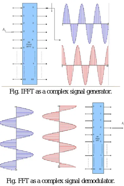
[image:3.612.153.550.373.701.2]efficient algorithms, the most common of which being the Cooley-Tukey fast Fourier transform (FFT), which is a rediscovery of an algorithm by mathematician Carl Frederich Gauss. The demodulation of the OFDM symbol is then the FFT of the received symbol which outputs a sequence of complex numbers. We continue with the assumption made in Chapter 2 that the channel is stationary during the transmission of at least one OFDM symbol.
Fig. IFFT as a complex signal generator.
Fig. FFT as a complex signal demodulator.
We must keep in mind that a cyclic prefix still needs to be added to the OFDM symbol to avoid ISI
The cyclic prefix needs to be removed before demodulation, which amounts to simply selecting the correct samples, namely n =
cp
[image:3.612.210.407.375.671.2]Technology (IJRASET)
IV. SYNCHRONIZATION ERRORS AND ESTIMATIONS
The most challenging aspect of designing a communication system is the estimation and correction of synchronization errors that occur during transmission. Synchronization of the system in time and frequency is still the source of much research and yet is one of the most often overlooked subjects in published papers [8].
This chapter is divided into two sections. The first gives mathematical descriptions of the synchronization errors present on OFDM systems. The effects of these errors on the received signals are analyzed and simulations of the errors are presented whose code can be found in Appendix D and Appendix E. The second section describes the estimation of the errors at the receiver. Figure 5.1 shows the block diagram of the synchronization process of a typical receiver. Simulations of the error estimations are presented using the IEEE802.11 standard for the OFDM frame structure
Fig.Synchronization blocks in OFDM receiver.
A. Synchronization Errors
In this section the effects of frequency and timing offsets will analyzed and simulated. As stated earlier, OFDM systems are very sensitive to frequency offsets between transmitter and receiver when modulating to pass band and back to baseband. Both ISI and inter channel interference (ICI) need to be mitigated as much as possible in order for the system to accurately receive data.
Much of the ISI can be eliminated with the addition of a guard interval or cyclic prefix. ICI is affected by the orthogonality of the subcarriers, which can be caused by Doppler shift or the offset in carrier frequency between the transmitter and receiver. Not only must frequency offsets be dealt with but also the sample clock and the frame or FFT window timing. Offsets in timing can cause ISI as well as ICI. In this section we will consider carrier frequency offset, symbol timing, and frame start position. We will not consider Doppler shift, as our concern lies in systems that behave as stationary, i.e. IEEE 802.11.
1) Frequency Offset: Let
f
c[Hz] be the carrier frequency offset and the normalized carrier frequency offset,
, be
=
f
c/
f
---(4.1)Where
f
is the sub-carrier bandwidth (sub-carrier spacing). There is not only the possibility of carrier frequency offset betweentransmitter and receiver, but also a phase difference θ0.
2) Sampling Clock Offset: At the receiver the incoming signal is sampled with an analog to digital converter (ADC). The ADC is
driven by the receiver clock which, in practice, is not perfectly synchronized with the transmitter clock.
3) Frame Timing Offset: The estimation of the OFDM symbol or frame start position determines the alignment of the FFT window
with the non-cyclically extended OFDM symbol. An offset in the FFT window can then include a neighboring OFDM symbol causing ISI, which can affect the orthogonality of the sub-carriers producing ICI. Analysis of the effects of frame timing offset on the constellation and the spectrum will be discussed with and without the use of a cyclic prefix for QPSK.
for 0 ≤ n ≤ Nfft − 1 and sub-carriers 0 ≤ k ≤ Nfft − 1. The received signal with channel impulse response hm[n] and AWGN zm[n] ,for channel impulse length Nc.
Technology (IJRASET)
Fig. Possible locations for frame start position.
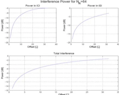
Fig. Power of ICI, ISI, and total interference for Nfft = 64.
B. Synchronization Error Estimation
Synchronization is separated into two categories, acquisition and tracking. In acquisition we focus on carrier frequency offset estimation, symbol timing and frame start position using the preamble structure outlined in IEEE802.11a [12]. Tracking occurs after the preamble has been sent and relies on information embedded into each OFDM frame to ensure carrier frequency and sample clock are locked during transmission.
1) Preamble Structure Of IEEE802.11a: Because of the sensitivity that OFDM has to frequency and timing offsets, measurements
must be taken to estimate and correct these offsets at the receiver. To accomplish this and other signal processing functions, four OFDM symbols are prepended to the OFDM burst transmission to aid in acquisition. After this preamble is processed, each successive frame contains four pilot symbols that are used for tracking frequency and timing.
Both the symbols in the preamble and the pilot symbols are known to the receiver. The first two OFDM frames contain ten short preambles and are used for automatic gain control, diversity selection, timing acquisition, and coarse frequency acquisition. We will focus our attention on the acquisition of timing and frequency. The zero packing has the effect of decreasing the symbol time by four, or Nfft/4, thus yielding the four copies in the time series. Thus, the short training symbols have 2.5 × Nfft symbols. In our application of OFDM, IEEE 802.11a/g, the bandwidth is 20MHz and the sample time is 1/20MHZ = 0.05μs. If we set Nfft = 64, as in IEEE802.11a, there are 16 samples in the short training symbol and so the symbol time is 16 × 0.05μs = 0.8μs. There are ten short training symbols which gives a total time of 8μs.
In this paper long training symbols are generated by taking the IFFT of the
26,26
L
= [1, 1,−1,−1, 1, 1,−1, 1,−1, 1, 1, 1, 1, 1, 1,−1,−1, 1, 1,− 1, 1,−1, 1, 1, 1, 1, 0, 1,−1,−1, 1, 1,−1, 1,−1, 1,−1, −1,−1,−1,−1, 1, 1,−1,−1, 1,−1, 1,−1, 1, 1, 1, 1]. ---(4.2)
Technology (IJRASET)
along with the added cyclic prefix, the total length of the long training symbols is 2.5 × Nfft. Again, we set Nfft = 64 so that the long training symbol is 64 samples long. With a sample time of 1/20MHZ = 0.05μs the long training symbol time is 64 × 0.05μs = 3.2μs. There are two long training symbols and a cyclic prefix of length 32 so the total time for the long training symbols is 2 × 3.2μs + 32 × 0.05μs = 8μs.
2) OFDM Frame Timing Estimation: Timing estimation is broken into two parts, frame timing or packet detection and symbol
timing. In both cases we use the preamble for detection. Here we start with frame timing and exploit the periodicity of the short training symbols using the auto-correlation as described in [23]. There are several algorithms for coarse timing but all use the correlation properties of the short training symbols. In this analysis, the delay and correlate algorithm presented in [23] and [9] is used. Fig. shows the block diagram for this algorithm.
[image:6.612.203.411.279.412.2]The top path, P(d), contains the cross-correlator and the bottom path, R(d), contains the auto-correlator. The δ value in the bottom path is to avoid division by zero. The auto-correlator computes the power in the samples and is used to normalize the decision at the threshold detector. The cross-correlator takes advantage of the periodicity in the short training symbols to locate the frame boundaries. Squaring helps mitigate the effects of large peak to average power ratios common in OFDM.
Fig. Delay and correlate algorithm.
3) Frequency Offset Estimation: Estimation of frequency offset during the acquisition phase is performed in two parts. Coarse
frequency offset uses the short training symbols and fine frequency offset uses the long training symbols. Both coarse and fine frequency estimation use the same algorithm, correlation with the received signal and a delayed copy. The conjugate product is then passed to a phase detector that outputs the phase error.Any algorithm used to estimate and correct frequency offset needs to operate with this amount of offset.
Fig. Frequency estimation algorithm.
[image:6.612.210.410.512.620.2]Technology (IJRASET)
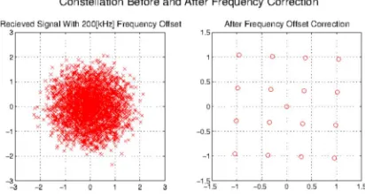
Fig. Constellation with and without frequency offset correction.
D. Symbol Timing Estimation: Symbol timing or fine timing is performed after coarse timing and after frequency offset correction.
Fine timing estimation uses the cross-correlation of the known long training symbol with the received long training symbol to determine the start and end of an OFDM symbol and consequently the start and end of the FFT window.
During the frame timing estimation, the starting edge of the packet was determined but within the packet symbol timing errors can be present. The cross-correlation of the known long training symbol and the received long training symbol can be determined .It is desirable to use the convolution operation since it can be performed using the FFT, which reduces the number of computations . There are two and a half long training symbols (the half symbol provided by the cyclic prefix) in the IEEE802.11a standard. Thus the cross-correlation should have three peaks, the first being about half the magnitude of the other two.
The first peak corresponds to the end of the cyclic prefix and the other two peaks correspond to the ends of the two long training symbols which have the same length as the OFDM symbol.
E. Channel Estimation: Let Y be the received signal, X the transmitted signal, and H the channel frequency response. Then
Y[K]=H[K]X[K]+Z[K]---(4.3)
where Z is the noise. Here we take advantage of the property of Fourier transforms, that convolution in the time domain corresponds to the product in the frequency domain. As stated in Chapter 2, it is assumed that the channel is stationary during each transmitted packet. We have then, setting Z[k] = 0,
In this way, the channel can be estimated but only if the transmitted signal is known. To this end, the long training symbols are used. Recall that the long training symbols use all sub-carriers (except DC) so that all used sub-carrier equalizer gains are found. Equation (3 )describes the channel frequency response for each sub-carrier but the inverse is needed to counter its effects:
F. Residual Frequency Offset: Carrier frequency offset was simulated and in Section 4.2.3, a method of estimation and correction
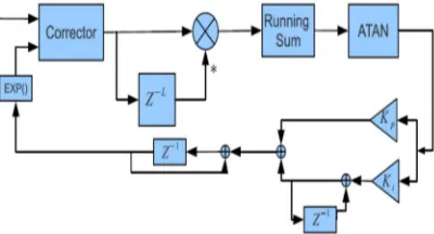
was put forward. The simulation showed very precise estimation that left the system with negligible errors. In real implementations of frequency offset estimation, the frequency offset is not constant (as simulated in section 4.1.1) and the system itself introduces thermal noise and phase degradation, which increases the error in carrier frequency offset [5]. This error is a residual frequency offset and while it may be small the accumulation of the offset can destroy the orthogonality of the sub-carriers. To continue tracking the frequency offset, each OFDM symbol contains four pilot subcarriers at frequency bins -21, –7, 7, 21 and are BPSK modulated using a pseudo-binary sequence [12].
The scrambler is initiated with all ones and produces the cyclically extended 127 element sequence P0 in equation4.4 :
0...126v
P
={1, 1, 1, 1,−1,−1,−1, 1,−1,−1,−1,−1, 1, 1,−1, 1,−1,−1, 1, 1,−1, 1, 1, − 1, 1, 1, 1, 1, 1, 1,−1, 1, 1, 1,−1, 1, 1,−1,−1, 1, 1, 1,−1,1,−1,−1,−1, 1, − 1, 1,−1,−1, 1,−1,−1, 1, 1, 1, 1, 1,−1,−1, 1, 1,−1,−1, 1,−1, 1,−1, 1, 1, − 1,−1,−1, 1, 1,−1,−1,−1,−1, 1,−1,−1, 1,−1, 1, 1, 1, 1,−1, 1,−1, 1, − 1, 1,−1,−1,−1,−1,−1, 1,−1, 1, 1,−1, 1,−1, 1, 1, 1,−1,−1, 1,−1,−1, −1, 1, 1, 1, 1, 1,−1,−1,−1,−1,−1,−1,−1} ---(4.4)
Technology (IJRASET)
Fig. Residual frequency tracking
V. RESULTS
[image:8.612.262.385.231.387.2]fig. Effects of multipath channel on received constellation
Fig.Channel estimation
Fig.Received constellation after channel correction -1.5 -1 -0.5 0 0.5 1 1.5 -1.5 -1 -0.5 0 0.5 1 1.5
Received Signal With Channel Distortion
In-Phase Q u a d ra tu re
-30 -20 -10 0 10 20 30 -60 -50 -40 -30 -20 -10 0 Frequency bin | H [f ]| ˆ2 [ d B ]
Multipath Channel with SNR=43.4293
Channel Estimation Channel Frequency Response
-1.5 -1 -0.5 0 0.5 1 1.5 -1.5 -1 -0.5 0 0.5 1
1.5 Received Signal With Channel Correction
[image:8.612.219.387.420.692.2]Technology (IJRASET)
Fig.Effects of normalized carrier frequency offset ǫ = 0.05 and SNR=20dB for 120 simulations
[image:9.612.232.377.283.435.2][image:9.612.199.407.464.702.2]
fig.Effects of normalized carrier frequency offset ǫ = 0.05 and SNR=20dB on the constellation for 120 OFDM Symbols.
Fig. Effects of normalized carrier frequency offset ǫ = 0.05 and SNR=20dB on the spectrum for 120 OFDM Symbols
-1.5 -1 -0.5 0 0.5 1 1.5 -1.5
-1 -0.5 0 0.5 1 1.5
Technology (IJRASET)
[image:10.612.207.399.53.579.2]
Fig. ICI coefficients forǫ = 0.5, 0.1, 0.05, 0.025.
Fig. Power of ICI.
Fig.Carrier-to-interference power ratio
VI. CONCLUSION
This thesis presented an introduction to MIMO-OFDM, specifically, the topics of the channel, OFDM, synchronization, and MIMO. Mathematical descriptions of the channel, OFDM, and synchronization, were given as well as MATLAB simulations to verify, illustrate concepts, or present a practical implementation. For each type of synchronization error, algorithms were presented and implemented in a MATLAB simulation. Future systems will include MIMO-OFDM and, as such, there is a lot of research being done in this area. One of the assumptions made about the channel was that it was static. While this assumption works well for standards such as IEEE802.11, it does not work well for cell phones and other wireless devices. In the future, we may see many devices that must be able to operate at speeds were Doppler shifts affect data transmission. Another consideration is the techniques used in space time coding. Turbo codes and low density parity-check codes are now replacing convolutional codes. Also, only the
0 0.05 0.1 0.15 0.2 0.25 0.3 0.35 0.4 0.45 0.5 -35 -30 -25 -20 -15 -10 -5 0
Normalized Carrier Frequency Offset
Pow
er
[dB]
ICI Power Resulting From Frequency Offset
Theoretical Approximation
0 0.05 0.1 0.15 0.2 0.25 0.3 0.35 0.4 0.45 0.5 0 10 20 30 40 50 60 70 80 90 100
Normalized Carrier Frequency Offset
C IR [ d B ]
Technology (IJRASET)
2x2 MIMO case was considered for STBCsREFERENCES
[1] J. Zhang, and Z. Zhang, “Simulation and Analysis of OFDM System Based on Simulink”, Institute of Electrical and Electronic Engineers, 2010. [2] V.N. Richard, and R. Prasad, “OFDM for Wireless Multimedia Communication”, Artech house Publisher, London, 2000.
[3] H. Harada, and R. Prasad, “Simulation and Software Radio for Mobile Communications”, Artech house Publisher, London, 2002.
[4] K. Srivinas, and Harishmittal, “ICI, SIR and BER of Various Pulse Shaping Functions Used in OFDM Communication Systems with Random Residual Carrier Frequency Offset”, International Journal of Advanced Electrical and Electronics Engineering (IJAEEE), vol. 2, Issue 5, 2013.
[5] S. Kim, and G.J. Pottie, “Robust OFDM in Fast Fading Channels”, Institute of Electrical and Electronics Engineers, GLOBECOM, 2003. [6] S. Hara, and R. Prasad, “Multicarrier Techniques for 4G Mobile Communications”, Artech House, Norwood, MA, 2003.
[7] J. Amstrong, “Analysis of new and existing methods of reducing intercarrier interference due to carrier frequency offset in OFDM”, IEEE Trans. Commun. 47(3), pp. 365-369, 1999.
[8] P.H. Moose, “A technique for orthogonal frequency division multiplexing frequency offset correction”, IEEE Trans. Commun. 42(10), pp. 2908-2914, 1994. [9] T. EnginTuncer, “ Optimum Nyquist Filters with Controlled Time and Frequency Characteristics”, Electronics Letter, vol. 38, no. 21, October 2002.
[10] C. Lin, G. Zhou, and T. Shim, “Reduction of ICI by using pulse shape in OFDM systems”, IEEE International Conference on Multisensor Fusion and Integration for Intelligent Systems Seoul, Korea, pp. 569-572, August 2008.
[11] M. Pal, “Algorithm for sharpening Raised Cosine Pulse Shaping Digital Filter and Analysis of performance of QAM system when subjected to Sharpened Raised Cosine Filter”, International Journal of Scientific and Research Publication, Volume 2, Issue1, January 2012.
[12] R. Gayathri, V. Sangeetha, S. Prabha, D. Meenakshi, and N.R. Raajan, “PAPR Reduction in OFDM Using Partial Transmit Sequence (PTS)”, International Journal of Engineering and Technology (IJET), vol. 5, no. 2, Apr-May 2013.