Technology (IJRASET)
Design and Control of Filter to Mitigate Zero
Sequence Harmonics in Power Distribution
Systems
Ch Bhaskar1, Ramu Nagapuri2, Nagaraju Goskula3 1
Assistant Professor, 2PG Student, 3Assistant Professor, KITS(S), Huzurabad.
Abstract: This project presents a technique to mitigate zero-sequence harmonics in power distribution systems. The method is based on the concept of passive zero-sequence harmonic filters. However, its basic configuration has been expanded to create a double-tuned filtering feature. This feature makes it possible to trap two harmonics with one filter and is especially attractive in solving harmonic-caused telephone interference problems. Furthermore, this project has shown that common utility service transformers can be used to construct the filter. As a result, a practical and low-cost solution to mitigating zero-sequence harmonics has been found. A method for sizing and loading assessment of filters has also been developed. As an example application, the presented filter package has been applied to mitigate a telephone interference problem. Issues, such as filter location, the number of filters required, and the effectiveness of filtering harmonics produced by distributed residential loads have been investigated. The results show that the presented filter is a very promising technique to reduce zero-sequence harmonics in primary power distribution systems.
Key Words: Power Quality, Harmonics, ZS Filter, VSI
I. INTRODUCTION
The mass penetration of energy-efficient consumer electronic devices has resulted in noticeable distortions to the voltage and current waveforms in power distribution systems. Although each consumer device is not a large source of harmonics, their collective effect can be significant. Home appliances have become a dominant source affecting the power quality (PQ) of residential distribution systems. Unlike industrial loads, most of the residential loads are single phase. This fact leads to the creation of zero-sequence (ZS) harmonic currents in three-phase distribution systems. It is quite common to observe high levels of ZS harmonics in a distribution system feeding residential loads these days. These harmonics can add up in the neutral conductor, creating problems such as neutral voltage raise. They are also the main culprit of telephone interference. There is, therefore, a growing interest by industry to develop solutions to mitigate the ZS harmonics.
A few passive ZS filters have been successfully used to mitigate ZS harmonics in commercial systems. Their variations have also been presented for applications in primary distribution systems. These filters have various topologies. All share the same idea– creating low ZS impedance to trap the ZS harmonics. The ZS filters can be broadly classified into two types. The first type has a positive- (and negative-) sequence impedance so it affects the flow of non-ZS harmonics. A representative example of these filters is the star-connected capacitors grounded through an inductance. The inductance is tuned to cause a low ZS impedance. The main advantage of this topology is that the capacitors can be tuned to filter positive- and negative-sequence harmonics as well. The downside is that the filter can affect the 60-Hz power flow and can lead to positive- or negative-sequence resonances at other frequencies.
Technology (IJRASET)
problems.
II. HARMONICS MIGITATION APPROACHES
Harmonic distortion in power distribution systems can be suppressed through three basic approaches namely:
Passive filter. Active power filter. Hybrid active power filter.
A. Hybrid Active Power Filter
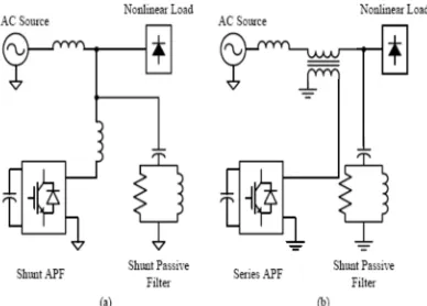
[image:3.612.204.398.397.536.2]Previously, majority of the controllers developed for APF are based on analogue circuits. As a result, the APF performance is inherently subjected to signal drift. Technical limitations of conventional APFs can be overcome with hybrid APF configurations. They are typically the combination of basic APFs and passive filters. Hybrid APFs, inheriting the advantages of both passive filters and APFs provide improved performance and cost-effective solutions. The idea behind this scheme is to simultaneously reduce the switching noise and electromagnetic interference. There are various hybrid APFs reported in literature but the two most prominent ones are shown in Fig. 2.6.The system configuration of the hybrid shunt APF as shown in Fig. 2.6(a). Both the shunt APF and passive filter are connected in parallel with the nonlinear load. The function of the hybrid APF can thus divided into two parts: the low-order harmonics are cancelled by the shunt APF, while the higher frequency harmonics are filtered by the passive HPF. Fig.2.6(b) shows the system configuration of hybrid series APF, in which the series APF is coupled to the distribution line by an interfacing transformer. The shunt passive filter consists of one or more single-tuned LC filter and / or a HPF. The hybrid series APF is controlled to act as a harmonic isolator between the source and nonlinear load by injection of a controlled harmonic voltage source. It is controlled to offer zero impedance (short circuit) at the fundamental frequency and high impedance (ideally open circuit) at all undesired harmonic frequencies. This forces all the nonlinear load current harmonics to flow into the passive filter, decoupling the source and nonlinear load at all frequencies, except at the fundamental.
Fig. 2.1 Configuration of Hybrid APFs (a) Combination of shunt APF and shunt passive filter (b) Combination of series APF and shunt passive filter
III. PRESENTED DOUBLE-TUNED ZS FILTER
It is well known that a transformer can sink ZS currents. This capability is the principle of a grounding transformer.
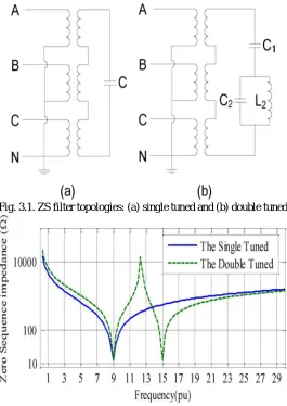
By inserting a capacitor into the delta loop and adjusting the capacitor size, very low ZS impedance can be created at a desired harmonic frequency. This package is called a single-tuned ZS filter [Fig. 3.1(a)].
Fig. 3.1(b) depicts the presentad double-tuned ZS filter, which can trap two harmonics by using only one transformer. This feature is very attractive for mitigating telephone interference problems as they are caused by the 9th and 15th harmonics. The use of only one single-tuned ZS filter will have difficulty in solving these problems. In Fig. 3.2, a sample ZS impedance frequency scan of the
presentad filter that was tuned to the 9th and 15th harmonic frequencies is shown and compared with the single-tuned version.
Technology (IJRASET)
where is the transformer secondary to primary winding ratio, is the power fundamental frequency (in radians per second), is the harmonic order, and are the transformer winding resistance and leakage inductance, transferred to the secondary side, respectively. From (1), the equivalent ZS impedance of the filter at harmonic order can be calculated
Next, the equivalent ZS circuit of the filter can be established as depicted in Fig. 3.3(b). Equation (2) shows that the capacitor can be tuned to make the reactance part of the filter impedance zero for a specific harmonic. In this case, the filter impedance at the tuned harmonic would be only the transformer winding resistance value transferred to the primary side. For example, to tune the filter to the 9th harmonic (by making the reactance part of (2) zero), the required capacitor size can be calculated as follows:
With a similar procedure, the equivalent ZS circuit of the presentad double-tuned ZS filter can be derived as shown in Fig. 3.3(c). The obtained equivalent ZS circuit is very similar to the conventional double-tuned filters shown in Fig. 3.4(b). Therefore, the proper component sizes of the presentad double-tuned ZS filter can be also derived by using a similar mathematical approach as follows:
[image:4.612.174.439.332.706.2]Fig. 3.1. ZS filter topologies: (a) single tuned and (b) double tuned
Technology (IJRASET)
Fig. 3.3. (a) ZS filter. (b) Equivalent ZS circuit of the single-tuned ZS filter. (c) Equivalent ZS circuit of the double-tuned ZS filter.
Fig. 3.4. (a) Paralleled conventional single-tuned filters. (b) Conventional double-tuned filter.
According to the equivalent impedances of two parallel conventional single-tuned filters [Fig. 3.4(a)] close to their tuned harmonic frequencies are almost the same as those of a conventional double-tuned configuration [shown in Fig. 3.4(b)], subject to the following relationships among their component parameters:
To establish the mathematical expressions for a double-tuned ZS filter tuned to the harmonic orders and , two single tuned ZS filters separately tuned to and can be considered with the respective capacitor sizes of and , as in
The two parallel single-tuned filters [Fig. 3.4(a)] are supposed to represent the equivalents of the two single-tuned ZS filters; therefore, their inductors and capacitors sizes are subject to the following relationships:
The component sizes of the double-tuned ZS filter can be obtained by using the equations set of (4). The only challenging issue involves , which is the transformer leakage inductance. By comparing Figs. 3.3(c) and 3.4(b), is observed to be equal to, on the other hand, according to (4), has to be
Technology (IJRASET)
divide/multiply the inductance/capacitance values by two) in order to satisfy (7) while keeping the tuned harmonic frequencies of the filter unchanged
Finally, combining (4), (6), and (8) will provide the final expressions for deriving the component sizes of the presented ZS double-tuned filter as follows:
where and are the capacitors tuned for the single-tuned ZS filters as defined in (5).
For the double-tuned and single-tuned ZS filters, the filter equivalent ZS impedance at the tuned frequencies is equal to the transformer winding resistance transferred to the primary side. For the filter to be effective, this resistance must be smaller than the system impedance.
IV. FILTER CONSTRUCTION AND DESIGN
Creating a low-resistance transformer does not involve any technical difficulties. However, constructing a ZS filter by using a specially designed MV transformer is highly uneconomical and must be avoided. A distribution utility company often has thousands of service transformers. If such transformers can be used, the filter cost can be reduced significantly. Furthermore, the LC components of the filter can be treated as the “loads” of the transformer. Installing a filter then becomes the same as adding a new “customer” to the system. Utility companies will be much more receptive to adopt the technology. To achieve this goal, two problems must be answered: 1) does the service transformers have sufficiently small resistance to be used as a ZS filter transformer? and 2) will the transformer be overloaded by the harmonics it traps?
To address the first question, the impedance characteristics of common service transformers are investigated. The results show that one three-phase or three single-phase service transformers in the range of total 100 kVA to 450 kVA are sufficient to create an effective ZS filter. The secondary side voltage can be 480 V
or 208 V. As a result, the proposed filter becomes a very attractive method for mitigating ZS harmonics. The transformer size can be determined by comparing the system impedance with the transformer resistance (see Section IV.E). A more accurate size determination may be accomplished through Harmonic Load Flow (HLF) studies. Once the transformer size is selected, specification of the other filter components can be derived by using (3) or (5), (9)–(11) for the single tuned or the double-tuned versions, respectively.
To address the second question, the transformer loading under harmonic conditions is assessed based on IEEE Standard C57. 110. An index called the transformer loading level (TLL) is developed. If the index exceeds 1 p.u. (indicating that the transformer is overloaded), a larger transformer must be utilized. The calculation of TLL becomes a part of the filter design process. Details are presented in the Appendix. The results have shown that service transformers have sufficient loading capability to handle harmonics. Additional issue to address is the loading assessment of the filter capacitors, which can be done based on standards. For the capacitors inside a ZS filter, however, their capacitance must not be changed in case of overloading (because the capacitances are strictly determined by the transformer specifications as in (9)–(10)). Therefore, to alleviate the loading of such capacitors, one has to increase their rated voltage and kvar without altering their capacitance.
IV. APPLICATION EXAMPLE
Technology (IJRASET)
Fig. 4. Schematic view of the studied distribution feeder.
A. System Description
Fig. 4 shows the schematic of the actual distribution feeder involved in the telephone interference problem. The feeder is located in Edmonton, Canada and is supplying two large residential neighborhoods (each neighborhood is encompassed by a circle in the figure labeled as the upstream and downstream harmonic loads). A telephone line is experiencing severe disturbing noises induced
from the feeder‟s adjacent overhead sections. The sections in parallel with the overhead power lines are shown by the dashed lines
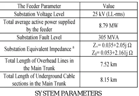
in Fig. 4 (The effect of the underground sections in noise induction is negligible since the neutral conductor is very close to the phase conductors in an underground cable and also carries the whole returning current, canceling out the overall generated electromagnetic field). The main characteristics of the feeder as provided by the utility company are listed in Table I.
TABLE I
SYSTEM PARAMETERS
B. System Model and Simulation Method
A comprehensive simulation platform was established to perform harmonic load flows on the studied system. The bottom–up probabilistic modeling approach introduced was employed to develop aggregated harmonic models for representing the distorting residential loads. The modeling technique replaces each group of a service transformer and its supplied residential customers by equivalent harmonic sources and impedances. Multiphase PI models were used for all the overhead lines and underground cables (including the single and double-phase sections) inside the feeder. A neutral wire was also included by employing multiphase
models. In order to evaluate the filters‟ effect of on the noises induced on the telephone lines, two sample parallel conductors were
also included in the model to represent the involved telephone line sections (the dashed lines in Fig. 4). Finally, the developed models were employed in a multiphase HLF program to perform the simulation studies. Since the models are time-varying during a day, the obtained results are for different times of the day.
C. Mitigation Objective
[image:7.612.196.421.394.549.2]Technology (IJRASET)
telephone lines [4]. Most of the ZS component of a harmonic current is dominated by the triplen harmonic orders such as 3rd, 9th, 15th. As well, for the telephone interference, the “ -message” factors determine the contribution of each harmonic frequency to the disturbing noise [4]. The factor is very small for the 3rd harmonic compared to that for the higher-order ones. Moreover, since the magnitude of the harmonic orders higher than 15th in residential distribution systems is negligible, the ZS 9th and 15th harmonic orders can be identified as the main contributors to a telephone interference problem. Therefore, the proposed double-tuned ZS filter will be tuned to the 9th and 15th harmonic frequencies.
As recommended by, the actual interference level can be quantified by multiplying the induced voltage of each harmonic frequency on the communication line by its corresponding -message factor. Therefore, an index called –message weighted voltage (CMWV) can be defined as follows:
where and are the induced voltage of the nth harmonic frequency on the telephone line and its corresponding –message weighting factor , respectively. Next, the total value of the CMWV as defined in (13) can exhibit the total interference level:
D. Filter Location
In order to effectively mitigate a telephone interference problem, installation of harmonic filters must eliminate the troublesome ZS harmonic currents in the power-line sections causing the disturbance. This section investigates the required number of filters and their appropriate placement in the studied feeder (shown in Fig. 6).
During the normal system condition, most load-generated harmonic currents flow to the substation due to the low supply system impedance. The ideal location for installing the filter to mitigate the telephone interference problem is at the downstream side of the telephone line such as location “F1” shown in Fig. 4. The filter is expected to sink the harmonics produced by the downstream loads. Thus, these harmonics will not travel upstream and interfere with the telephone line upstream. However, an important issue must be addressed here: Will the filter also attract the harmonics from the upstream loads? If the filter does so, it may not be able to reduce the telephone interference level. HLF simulation results can determine whether this issue will be a problem or not. If a problem is caused in the mitigation, then two filters will be required, and the second one will need to be installed at the location between the telephone line and the upstream loads (labelled by in Fig. 4).
E. Filter Design Results
For selecting the transformer size, some of the typical sizes of the three-phase transformers used by the utility company in their 25 kV voltage level distribution systems are listed in Table III. The ZS impedance of the filter at the tuned harmonics (which is, in fact, the transformer resistance) obtained by each of the transformer sizes is also provided in the last column.
On the other hand, the system model was also used to estimate the system equivalent ZS impedance at the 9th and 15th harmonic frequencies at the proposed filter location (in Fig. 4). The obtained minimum values during the day are 56.84 and 41.6 for the 9th and 15th harmonic orders, respectively. Because of these values, the transformer size of 225 kVA is adopted as the minimum transformer size to be used in the ZS filter design procedure.
In order to establish a sound understanding of the discussed ZS filters performance, the HLF simulation results for the following cases are also presented and discussed in this section.
Case 1) normal system condition before installing any filter;
Case 2) one single-tuned version of the designed ZS filter (with the 450 kVA transformer in Table IV) is installed in location F1; Case 3) two single-tuned versions of the designed ZS filter (with the 450 kVA transformer in Table IV) are installed in locations F1 and F2;
Case 4) one double-tuned version of the designed ZS filter (with the 450 kVA transformer in Table IV) is installed in location F1; Case 5) one double-tuned version of the designed ZS filter but with a larger transformer size of 1000 kVA is installed in location F1; Case 6) two double-tuned versions of the designed ZS filter (with the 450 kVA transformer in Table IV) are installed in the locations F1 and F2 (This case presents the recommended filter set to completely fulfill the mitigation objective).
Individual demand distortion (IDD) of the dominant sequence harmonic currents calculated at the “Monitoring Location” shown in Fig. 4;
The frequency spectrum of the total induced voltage on the parallel conductor representing telephone line;
The -message weighted values of the induced noise voltages ( and , which were used for defining the mitigation objective);
Power-line IT at the “Monitoring Location” shown in Fig. 4. Instead of presenting and analyzing the whole 24-h profiles of the
Technology (IJRASET)
the time, the index is below this value. The following are the key observations from the simulation results:
By lowering the total CMWV from 56.5 to 12 V, the goal of a 75% decrease in the interference level was achieved (Fig. 5). Power-line IT is also decreased from around 10000 to 2000 in this case, demonstrating the effectiveness of the filter in the reduction of telephone interference.
The double-tuned ZS filters were found to be effective in mitigating both the 9th and 15th harmonics. Although the single-tuned versions could suppress the 9th harmonic, they were unable to mitigate the 15th harmonic. The 15th harmonic component was observed to increase in the single-tuned filter cases (II & III) resulting in mitigation failure (See Figs. 5 and 6). This phenomenon is likely due to a parallel resonance between the filter and the system at the 15th harmonic frequency. At this harmonic frequency, the filter is inductive and the system is capacitive because of the shunt capacitance of the underground cables. Such observations once again confirm the need to use the proposed double-tuned ZS filter to mitigate a telephone interference problem.
V. SIMULATION RESULTS
Fig.5.1 Simulation model Case 1
Discrete, Ts = 5e -005 s.
A B C + -A B C + -N A B C N A B C Vabc IabcA B C a b c Vabc IabcA B C a b c Vabc IabcA B C a b c Va bc
Ia bcA B
C a b c
9.7 9.75 9.8 9.85 9.9 9.95 10
-500 0 500
9.7 9.75 9.8 9.85 9.9 9.95 10
-40 -20 0 20 40 Time
9.7 9.75 9.8 9.85 9.9 9.95 10
-500 0 500
9.7 9.75 9.8 9.85 9.9 9.95 10
-40 -20 0 20 40 Time
9.7 9.75 9.8 9.85 9.9 9.95 10
-500 0 500
9.7 9.75 9.8 9.85 9.9 9.95 10
Technology (IJRASET)
Fig.5.2 Simulation results Case 1
Fig.5.3 Simulation model Case 2
9.7 9.75 9.8 9.85 9.9 9.95 10
-500 0 500
9.7 9.75 9.8 9.85 9.9 9.95 10
-40 -20 0 20 40 Time Discrete, Ts = 5e-005 s.
A B C + -A B C + -N A B C N A B C A B C A B C A B C A B C Vabc Iabc A B C a b c Vabc Iabc A B C a b c Vabc IabcA B C a b c Vabc IabcA B C a b c 1 2 1 2 1 2
3.9 4 4.1 4.2 4.3 4.4 4.5
-500 0 500
3.9 4 4.1 4.2 4.3 4.4 4.5
-20 -10 0 10 20 Time
3.9 4 4.1 4.2 4.3 4.4 4.5
-500 0 500
3.9 4 4.1 4.2 4.3 4.4 4.5
-150 -100 -50 0 50 100 Time
3.9 3.95 4 4.05 4.1 4.15 4.2
-500 0 500
3.9 3.95 4 4.05 4.1 4.15 4.2
Technology (IJRASET)
Fig.5.4 Simulation results Case 2
Fig.5.5 Simulation model Case 3
3.9 3.95 4 4.05 4.1 4.15 4.2
-500 0 500
3.9 3.95 4 4.05 4.1 4.15 4.2
-100 -50 0 50 100 150 Time Discrete, Ts = 5e-005 s.
A B C + -A B C + -N A B C N A B C A B C A B C A B C A B C Vabc IabcA B C a b c Vabc IabcA B C a b c Vabc IabcA B C a b c Vabc Iabc A B C a b c 1 2 1 2 1 2 1 2 1 2 1 2
7.8 7.85 7.9 7.95 8 8.05 8.1 8.15 -400
-200 0 200 400
7.8 7.85 7.9 7.95 8 8.05 8.1 8.15 -20 -10 0 10 20 Time
7.8 7.85 7.9 7.95 8 8.05 8.1 8.15 -400
-200 0 200 400
7.8 7.85 7.9 7.95 8 8.05 8.1 8.15 -4 -2 0 2 4 Time
7.8 7.85 7.9 7.95 8 8.05 8.1 8.15
Technology (IJRASET)
Fig.5.6 Simulation results Case 3
Fig.5.7 Simulation model Case 4
7.8 7.85 7.9 7.95 8 8.05 8.1 8.15
-400 -200 0 200 400 600
7.8 7.85 7.9 7.95 8 8.05 8.1 8.15
-5 0 5
Time
Discrete , Ts = 5e -005 s.
A B C + -A B C + -N A B C N A B C A B C A B C A B C A B C Va bc Ia bc A B C a b c Vabc Iabc A B C a b c Va bc Ia bc A B C a b c Va bc
Ia bcA B C a b c 1 2 1 2 1 2
7.8 7.85 7.9 7.95 8 8.05 8.1 8.15
-500 0 500
7.8 7.85 7.9 7.95 8 8.05 8.1 8.15
-20 -10 0 10 20 Time
7.8 7.85 7. 9 7.95 8 8.05 8.1 8. 15
-500 0 500
7.8 7.85 7. 9 7.95 8 8.05 8.1 8. 15
-100 -50 0 50 100 Time
7.8 7.85 7.9 7.95 8 8.05 8.1 8.15
-2000 -1000 0 1000 2000
7.8 7.85 7.9 7.95 8 8.05 8.1 8.15
-5 0 5
Time
7.8 7.85 7.9 7.95 8 8.05 8.1 8.15
-500 0 500
7.8 7.85 7.9 7.95 8 8.05 8.1 8.15
Technology (IJRASET)
Fig.5.9 Simulation model Case 5
Discrete, Ts = 5e-005 s.
A B C + -A B C + -N A B C N A B C A B C A B C A B C A B C Vabc Iabc A B C a b c Vabc Iabc A B C a b c Vabc Iabc A B C a b c Vabc IabcA B C a b c 1 2 1 2 1 2
7.8 7.85 7.9 7.95 8 8.05 8.1 8.15 -500
0 500
7.8 7.85 7.9 7.95 8 8.05 8.1 8.15 -20 -10 0 10 20 Time
7.8 7.85 7.9 7.95 8 8.05 8.1 8.15
-500 0 500
7.8 7.85 7.9 7.95 8 8.05 8.1 8.15
-100 -50 0 50 100 Time
7.8 7.85 7.9 7.95 8 8.05 8.1 8.15
-2000 -1000 0 1000 2000
7.8 7.85 7.9 7.95 8 8.05 8.1 8.15
-5 0 5
Time
7.8 7.85 7.9 7.95 8 8.05 8.1 8.15 -500
0 500
Technology (IJRASET)
Fig.5.11 Simulation model Case 6
Fig.5.11 Simulation results Case 6
VI. CONCLUSION
This project has presented a novel and effective filter to mitigate ZS harmonics in the power systems. The design and construction
Discrete, Ts = 5e-005 s.
A B C + -A B C + -N A B C N A B C A B C A B C A B C A B C Vabc IabcA B C a b c Vabc IabcA B C a b c Vabc IabcA B C a b c Vabc IabcA B C a b c 1 2 1 2 1 2 1 2 1 2 1 2
7.8 7.85 7.9 7.95 8 8.05 8.1 8.15
-400 -200 0 200 400
7.8 7.85 7.9 7.95 8 8.05 8.1 8.15
-20 -10 0 10 20 Time
7.8 7.85 7.9 7.95 8 8.05 8.1 8.15
-400 -200 0 200 400
7.8 7.85 7.9 7.95 8 8.05 8.1 8.15
-4 -2 0 2 4 Time
7.8 7.85 7.9 7.95 8 8.05 8.1 8.15
-2000 -1000 0 1000 2000
7.8 7.85 7.9 7.95 8 8.05 8.1 8.15
-5 0 5
Time
7.8 7.85 7.9 7.95 8 8.05 8.1 8.15
-400 -200 0 200 400
7.8 7.85 7.9 7.95 8 8.05 8.1 8.15
-5 0 5
Technology (IJRASET)
issues of the filters are fully investigated. The main findings and contributions of this work can be summarized as follows.
A. The presented filter can trap two harmonics simultaneously. It becomes a very attractive method to mitigate telephone
interference problems.
B. The filter can be constructed using regular service transformers and low voltage LC components. As a result, it is a very
cost-effective filter. Installing a filter is as simple as adding a customer to the distribution system.
C. A practical design procedure has been developed for the filter. This project also presented a method for the loading assessment
of the filter transformer.
D. The presented filter package and its design method have been tested through computer simulation studies. The results have
shown that the filter is quite effective to trap ZS harmonics and is an attractive solution to the telephone interference problem. Field tests on the presented filter are presently being pursued. The results will be presented in the future. Another application of the filter includes mitigating the harmonic-caused neutral voltage/current rise.
REFERENCES
[1] P. Bagheri, “Methods to mitigate harmonics in residential power distribution systems,” M.Sc. dissertation, Dept. Elect. Comput. Eng., Univ. Alberta, Edmonton, AB, Canada, 2013.
[2] T. Q. Tran, L. E. Conrad, and B. K. Stallman, “Electric shock and elevated EMF levels due to triplen harmonics,” IEEE Trans. Power Del., vol. 11, no. 2, pp. 1041–1049, Apr. 1996.
[3] T. M. Gruzs, “A survey of neutral currents in three-phase computer power systems,” in Proc. Ind. Commercial Power Syst. Tech. Conf., May 7–11, 1989, pp. 114–122.
[4] “IV.B. Power line harmonic effects on communication line interference IEEE working group on power system harmonics,” IEEE Power Eng. Rev., vol. PER-5, no. 9, p. 56, Sep. 1985.
[5] W. Jewell, W. Miller, and T. Casey, “Audible telephone noise from small harmonic sources on single-phase distribution,” in Proc. 8th Int. Conf. Harmonics Qual. Power, Oct. 14–18, 1998, vol. 2, pp. 890–895.
[6] W. Xu and V. Sharma, “Evaluation of the use of zero sequence harmonic traps in commercial buildings,” CEA, Project rep. 311-D-937, 1998.
[7] P. Rodriguez, I. Candela, S. Bogarra, R. Teodorescu, and F. Blaabjerg, “Cancellation of neutral current harmonics by using a four-branch star hybrid filter,” in Proc. IEEE 8th Power Electron. Specialists Conf., Jun. 15–19, 2008, pp. 1041–1047.
[8] “Passive power filter tunable at two simultaneous frequencies, one for zero-sequence and another on for positive-sequence ,” (in Spanish) Spanish patent ES2253095, Jan. 2007.
[9] W. Jewell, W. L. Miller, and T. Casey, “Filtering dispersed harmonic sources on distribution,” IEEE Trans. Power Del., vol. 15, no. 3, pp. 1045–1051, Jul. 2000.
[10] C. Wu, J. Chiang, S. Yen, C. Liao, J. Yang, and T. Guo, “Investigation and mitigation of harmonic amplification problems caused by singletuned filters,” IEEE Trans. Power Del., vol. 13, no. 3, pp. 800–806, Jul. 1998.
[11] H. Jou, J. Wu, K. Wu, W. Chiang, and Y. Chen, “Analysis of zig-zag transformer applying in the three-phase four-wire distribution power system,” IEEE Trans. Power Del., vol. 20, no. 2, pt. 1, pp. 1168–1173, Apr. 2005.
[12] E. Larsen, “Filter for removing harmonic current from a neutral conductor,” U.S. Patent 5 914 540, Jun. 22, 1999. [13] J. Arrillaga and R. W. Neville, Power System Harmonics, 2nd ed. Hoboken, NJ, USA: Wiley, 2003.
[14] IEEE Standard for Shunt Power Capacitors, IEEE Standard 18-2002 (Rev. of IEEE Standard 18-1992).
[15] D. Salles, C. Jiang, W. Xu, W. Freitas, and H. E. Mazin, “Assessing the collective harmonic impact of modern residential loads—Part I: Methodology,” IEEE Trans. Power Del., vol. 27, no. 4, pp. 1937–1946, Oct. 2012.
[16] C. Jiang, D. Salles, W. Xu, and W. Freitas, “Assessing the collective harmonic impact of modern residential loads – Part II: Applications,” IEEE Trans. Power Del., vol. 27, no. 4, pp. 1947–1955, Oct. 2012.
[17] W. Xu, J. R. Marti, and H. W. Dommel, “A multiphase harmonic load flow solution technique,” IEEE Trans. Power Syst., vol. 6, no. 1, pp. 174–182, Feb. 1991.
[18] IEEE Recommended Practice for Inductive Coordination of Electric Supply and Communication Lines, IEEE Standard 776-1992, Feb. 8, 2012. [19] IEEE Recommended Practices and Requirements for Harmonic Control in Electrical Power Systems, IEEE Standard 519-1992, 1993.
[20] J. M. Frank, “Development and design of -factor transformers,” in Proc. IEEE Ind. Appl. Soc. Annu. Meeting Conf. Rec., Denver, CO, USA, 1994, pp. 2273– 2274.
[21] R. D. Henderson and P. J. Rose, “Harmonics: The effects on power quality and transformers,” IEEE Trans. Ind. Appl., vol. 30, no. 3, pp. 528–532, May/Jun. 1994.
[22] IEEE Recommended Practice for Establishing Liquid-Filled and Dry- Type Power and Distribution Transformer Capability When Supplying Nonsinusoidal Load Currents, EEE Standard C57.110-2008 (Revision of IEEE Standard C57.110-1998), Aug. 15, 2008.