Technology (IJRASET)
©IJRASET 2013: All Rights are Reserved
546
Improving the Power Quality Based On
VSC-DSTATCOM with Back Propagation Algorithm
through Neural Network
R.Bharathi1 Dr. R.Arivalahan2
1
PG Scholar, 2 Associate Professor, Department of Electrical and Electronics Engineering, Valliammai Engineering College, Chennai
Abstract—this paper presents a three phase three wire Distributed Static Compensators (DSTATCOM) is proposed for an Power Quality improvement. DSTATCOM is a shunt device which is generally used to minimize power quality problems in distribution system. Here DSTATCOM using a Back Propagation (BP) Control Algorithm for Voltage Sag/Swell, Reactive Power Compensation, and load balancing, harmonic elimination under linear and non-linear loads. A BP-based Control Algorithm extracts reference source currents and is fed to the PWM technique to generate gate signals to the IGBT switches of VSC used DSTATCOM. Performance of the DSTATCOM is evaluated under various operating conditions using simulation model in MATLAB/SIMULINK.
Index terms—Back Propagation (BP) Control Algorithm; Distributed Static Compensator; Power Quality; Load Compensation; Load Balancing.
I. INTRODUCTION
Power quality is certainly a major issue in present era. Electrical power quality problems mainly include problems such as voltage unbalancing, flicker, harmonics, voltage sag, voltage swell, power interruption [1]. This issue is more serious in electronic systems. The harmonic level, reactive power demand are parameters that specify the degree of distortion and reactive power demand at the bus of utility [2]. Power converter-based custom power device are mostly used in reducing the power quality issues such as voltage sag and voltage swell compensation, resonance due to distortion and voltage flicker reduction within limits [3]. The performance of custom power devices depends on the control algorithm used for the estimation of reference current and pulse generation scheme. Some of the classical control algorithms p-q theory and SRF theory [3][4]. DSTATCOM has more technical advantage over SVC, they have fast response time, require less space as bulky passive components are eliminated and can be interface with real power sources such as battery, fuel cell [5]. A DSTATCOM has superior performance during low voltage condition as the reactive current can be maintained constant. The performance of the DSTATCOM depends on any control algorithm that has been applied for the extraction of reference currents. Many current control algorithm has reported for VSC based controllers [7][8]. DSTATCOM uses voltage source converters to improve productive similar to a traditional SVC and the DSTATCOM can be used to restore voltage and current. Neural network trains in Adaptive learning, self-organization, real-time operation and fault tolerance through redundant information are major advantage of these algorithm. A neural network control algorithms such as the Hopfield-type neural network is also used for the estimating the magnitude and the phase angles of the fundamental component with highly distortion voltage by the assumption of know power frequency. An improvement adaptive detecting approach for the extraction of the error signal with variable learning parameters is chosen for fast response to improve tracking speed and for low value in a stable period to improve accuracy [9]. Feedfoward back propagation (BP) Artificial Neural Network (ANN) consist of various layer such as the input layer, hidden layer and output layer. It is based on feedforward BP with a high ability to deal with complex non-linear problems [10]. In this BP algorithm, the training of weights has three stages. Firstly comes the feedforward for the given inputs signal training, calculation and BP of the error signals and upgrading of training the weights[11]. It has one or more layer that is continuity, differentiability, and non decreasing monotony these are the main characteristics of this algorithm. The proposed control algorithm on DSTATCOM is implemented for the compensation of non-linear loads.
II. BASIC PRINCIPLE OF DSTATCOM
A. DSTATCOM
Technology (IJRASET)
©IJRASET 2013: All Rights are Reserved
547
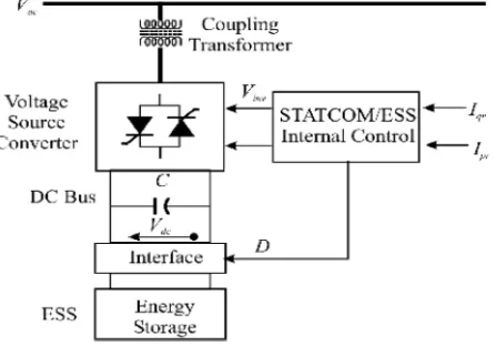
[image:3.612.193.417.234.390.2]order to generate and absorb the reactive power. The terminals of the VSC in AC system are connected to the point of common coupling through an inductance which will filter the leakage inductance of coupling transformer. The DC side converter is connected and the input ripple current of the converter is controlled by DC Capacitorand is the reactive power, energy storage element. This capacitor could be recharge by a battery source. If the output voltage of VSC is higher than the terminal voltage of AC system, the DSTATCOM operates in capacitor mode. DSTATCOM is used for voltage regulation at the PCC for the compensation should be in such a way that the supply current should lead the supply voltage and for power factor correction and the supply current should be in phase with supply voltage. DSTATCOM differs when compared with other reactive power generating devices such as shunt capacitor, static VAR compensators. These senses that the ability for system unbalance or harmonic absorption. DSTATCOM has some of the benefits such as increasing power transfer capability, improved voltage stability, improved power factor, improved grid voltage control, elimination flicker, voltage balancing, power factor correction. Some of the major application where DSTATCOM used is power quality means flicker mitigation and grid voltage support.
Fig 1.Basic structure of DSTATCOM
B. Operation And Configuration
DSTATCOM is a three phase and shunt power electronics based device and it is connected close to the load at the distribution systems. DSTATCOM is viewed as a variable current source obtained by a control function in order to improve the dynamic rating of capacitive range as a fixed capacitor or filter is connected in parallel with DSTATCOM. A energy storage device on DC side is for exchanging the real power with the network for a limited time during voltage sag. DSTATCOM has three modes of operation. Mode 1 operation no load mode Vs=Vi then I=0. Mode 2 operation is inductive mode Vs>Vi then I is said to be have leading current. The magnitude of the current can be controlled by adjusting Vi here DSTATCOM will act as an capacitive reactance. Mode 3 operation is capacitive mode Vs<Vi then I will said to have an lagging current, here DSTATCOM will act as inductive reactance. C. VSC-DSTATCOM
AVSC based DSTATCOM is connected at the three phase ac mains feeding three phase linear or non linear loads with internal grid impedance. The performance of DSTATCOM depends on the accuracy of harmonic current detection. In order to reduce the ripple in compensating currents, the tuned values of interfacing inductors are connected at the output of VSC. A three phase series combination of capacitor and resistor which act as a shunt passive filter which is connected at a point of common coupling. These filter is for reducing the high frequency switching noise of VSC. The DSTATCOM currents are injected as required for the compensating currents in order to cancel the reactive power and harmonics of that load currents so that loading due to reactive power and harmonics is reduced on distribution system. The control algorithm used here is BP training algorithm, and this BP algorithm is used for the estimation of the reference source currents by calculating the weighted value of the active power and the reactive power current components. The input for this BP algorithm is, the phase PCC (Vsa,Vsb,Vsc), source currents (isa,isb,isc), load current (iLa, iLb, iLc), and dc bus voltage(Vdc) are required for the extraction of source current. In BP control algorithm there are
Technology (IJRASET)
©IJRASET 2013: All Rights are Reserved
548
[image:4.612.150.438.91.291.2]error or supervised learning.
Fig 2. Schematic diagram of VSC-DSTATCOM
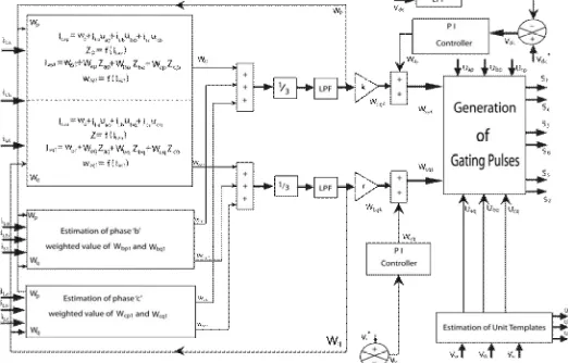
III. PROPOSED CONTROL ALGORITHM
This BP control algorithm for the estimation of various control parameters is as follows.
A. Weighted Function Value Of Average Active And Reactive Power Components At Fundamental
A BP training algorithm is used here for the estimation of the weighted value of load active components (Wap, Wbp, Wcp) and reactive
component (Waq, Wbq, Wcq) from the polluted load currents using the feedforward and supervised principle. The input layer for a
three phases (a,b,c) is expressed as,
ILap= W0+iLaUap+iLbUbp+iLcUcp
ILbp= W0+iLbUbp+iLcUcp+iLaUap (1)
ILcp= W0+iLcUcp+iLaUap+iLbUbp
W0= Selected value of the initial value of initial weight
Uap,Ubp,Ucp= in-phase unit templates.
In-phase unit templates are calculated by PCC phase voltage (Vsa,Vsb,Vsc). Relation between the phase voltage and amplitude of the
PCC voltage (Vt). The amplitude of sensed PCC voltage is estimated as
(2) The In-phase unit templates of PCC voltages (Uap, Ubp, Ucp) are considered as,
Uap=Vsa/Vt;
Ubp=Vsb/Vt (3)
Ucp=Vsc/Vt;
The extracted values of ILap, ILbp, and ILcp is given to the sigmoid function as an activation function, and the outputsignals are (Zap, Zbp, and Zcp) of the feedforward section are expressed as
Zap= f(ILap) = 1/(1+e -ILap)
Zbp= f(ILbp) = 1/(1+e -ILbp) (4)
Zcp= f(ILcp) = 1/(1+e -ILcp)
The estimated values of Zap, Zbp, and Zcpare fed to a hidden layer as input signals. The 3 phase outputs of this layer (Iap1, Ibp1, and Icp1) before the activation function are expressed as
Technology (IJRASET)
©IJRASET 2013: All Rights are Reserved
549
Ibp1 = W01+ WbpZbp+WcpZcp+WapZap (5)
Icp1= W01+ WcpZcp+WapZap+WbpZbp
WhereWo1, Wap, Wbp, and Wcp are the selected value of initial weight in hidden layer and the updated values of three phase weights using average weighted function value(Wp) of the active power current as a feedback signal.
The updated weights of phase “a” its active power components of load current “Wap” at the nth sampling instant is expressed as Wap(n) = Wp(n) + [Wp(n) – Wap1(n)] f’ (Iap1)Zap(n) (6)
where Wp(n)and Wap(n)are the average weighted value of the active power of load currents and the updated weighted value of phase “a” at the nth sampling instant respectively.Wap1(n)and Zap(n)are the phase “a” over all weighted value of the active power of the load current and the output of the feedforward of algorithm at the nth instant, respectively. f_(Iap1) and μ are represented as the derivative of Iap1 components and the learning rate.
Similarly, for phase “b” and phase “c,” the updated weighted values of the active power components of the load current are expressed as
Wbp(n) = Wp(n) + [Wp(n) – Wbp1(n)] f’ (Ibp1)Zbp(n)
Wcp(n) = Wp(n) + [Wp(n) – Wcp1(n)] f’ (Icp1)Zcp(n) (7)
The extracted values of Iap1, Ibp1, and Icp1 is given to the sigmoid function as an activation function to the estimation of the
fundamental active components in terms of three phase weights Wap1, Wbp1 and Wcp1
Wap1 = f(Iap1) = 1/(1+e –Iap1)
Wbp1 = f(Ibp1) = 1/(1+e –Ibp1) (8)
Wcp1 = f(Icp1) = 1/(1+e –Icp1)
The average weighted magnitude of the fundamental active power (Wp) is estimated using the amplitude sum of the 3 phase load
active power(Wap1, Wbp1 and Wcp1)divided by three. It is required to generate load balancing, given as
Wp = (Wap1 + Wbp1 + Wcp1) / 3 (9)
First-order low-pass filters are used to separate the low frequency components. Where “k” denotes the scaled factor. This extracts the value of active power of current in this algorithm. After separation, low-frequency components are scaled to the actual value because the output of the activation function must lie between 0 and 1 and it is represented as WLpA.
Similarly, the weighted amplitudes of the reactive power of the load currents (Waq, Wbq, and Wcq) of the overall load current are
extracted as
ILaq = W0 + iLaUaq + iLbUbq+ iLcUcq
ILbq = W0 + iLbUbq + iLcUcq+ iLaUaq (10)
ILcq = W0+ iLcUcq+ iLaUaq + iLbUbq
Where W0 is the selected values of starting weight and Uaq, Ubq, and Ucq are the quadrature components of the unit template. This unit templates (Uaq, Ubq and Ucq)of the phase Point of Common Coupling voltage are estimated as
Uaq = (-3Uap+Ubp + Ucp)/ ;
Ubq = (3Uap + Ubp - Ucp)/ ; (11)
Ucq= (-3Uap + Ubp - Ucp)/ ;
The extracted values of ILaq, ILbq, and ILcq is given to the sigmoid function as the activation function to the estimation of Zaq, Zbq, and Zcq
Zaq= f(ILaq) = 1/(1+e -ILaq)
Technology (IJRASET)
©IJRASET 2013: All Rights are Reserved
550
Zcq= f(ILcq) = 1/(1+e -ILcq)
The estimated values of Zaq, Zbq, and Zcq are given to the to the hidden layer as input signals. The 3 phase outputs of this layer is (Iaq1, Ibq1, and Icq1) before the activation function can be represented as
Iaq1= W01+ WaqZaq+WbqZbq+WcqZcq
Ibq1= W01+ WbqZbq+WcqZcq+WaqZaq (13)
Icq1= W01+ WcqZcq+WaqZaq+WbqZbq
Where Wo1, Waq, Wbq, and Wcqare the selected value that is starting weight in hidden layer and the updated three weights by the average weighted value of the reactive power (Wq) as a feedback signal, respectively
The updated weight of the single phase “a” reactive power of load currents “Waq” at the nth sampling instant is expressed as Waq(n) = Wq(n) + [Wq(n) – Waq1(n)] f’ (Iaq1)Zaq(n) (14)
Wq(n) and Waq(n)are the average weighted value of reactive power of load currents and weight in the nth sampling instant and Waq1(n),Zaq(n)are the single phase “a” weighted amplitude of the reactive power current of load currents and the output of the feedforward of the algorithm at the nth instant, respectively. f’(Iaq1) and μ are represented as the derivative of Iaq1components and the learning rate.
Similarly, for phase “b” and “c,” the updated weighted values of the reactive power current of the load current is expressed as Wbq(n) = Wq(n) + [Wq(n) – Wbq1(n)] f’ (Ibp1)Zbp(n)
Wcq(n) = Wq(n) + [Wq(n) – Wcq1(n)] f’ (Icp1)Zcp(n) (15)
The extracted values of Iaq1, Ibq1, and Icq1given to the activation function to the estimation of the fundamental reactive component in terms of three phase weights Waq1, Wbq1, and Wcq1as
Waq1 = f(Iaq1) = 1/(1+e –Ilaq1)
Wbq1 = f(Ibq1) = 1/(1+e –Ilaq1) (16)
Wcq1 = f(Icq1) = 1/(1+e –Ilaq1)
The average weight of the amplitudes of the fundamental reactive power components (Wq) is estimated using the amplitude summation of the three phase load reactive power components of the load current (Waq1, Wbq1, and Wcq1) divided by three. Mathematically, it is expressed as
Wq = (Waq1 + Wbq1 + Wcq1) / 3 (17)
[image:6.612.174.435.520.687.2]First-order low-pass filters are used to separate the low frequency component. “r” denotes the scaled factor. This will have the extracted value of reactive power components in the algorithm. After separating low-frequency components and scaling to the actual value because the output of the activation function is between 0 and 1, it is represented as WLqA.
Technology (IJRASET)
©IJRASET 2013: All Rights are Reserved
551
B. Active Power Current Components Of Reference Source Current
An error in the dc voltage is obtained by comparing the reference dc bus voltage V*dcand the sensed dc bus voltage Vdc of a VSC,
and this error at the nth sampling instant is expressed as
Vde (n) = V*dc(n) – Vdc(n) (18)
This error voltage is fed to a proportional Integral (PI) controller whose output is required for maintaining the dc bus voltage of the DSTATCOM. At the nth sampling instant, the output of the PI controller is as follows:
Wdp(n) = Wdp(n-1)+Kpd[Vde(n)-Vde(n-1)]+KidVde(n) (19)
Where kpd and kid are the proportional and integral gain constants of the dc bus PI controller. Vde(n)and Vde(n − 1)are the dc bus voltage errors in the nth and (n − 1)th instant, and Wdp(n)and Wdp(n − 1)are the amplitudes of the active power component of fundamental reference current at the nth and (n−1)th instant. The amplitude of the active power current components of the reference source current (Wspt) is estimated by the addition of the output of the dc bus PI controller (Wdp) and the average magnitude of the load active currents (WLpA)as
Wspt = Wdp+WLpA (20)
C. Reactive Power Component Of Reference Source Currents
An error in the ac bus voltage is achieved after comparing the amplitudes of the reference ac bus voltage v∗
t and the sensed ac bus
voltage vtof a VSC. The extracted ac bus voltage error vte at the nth sampling instant is expressed as
Vte(n) = V*t(n) – Vt(n) (21) The weighted output of the ac bus PI controller Wqq for regulating the ac bus terminal voltage at the nth sampling instant is expressed as
Wqq(n) = Wqq(n-1)+Kpt[Vte(n)-Vte(n-1)]+KitVte(n) (22)
Where Wqq(n) is part of the reactive power component of the source current and it is renamed as Wqq. Kpt and kit are the proportional Integral constants gain of the ac bus voltage PI controller. The amplitude of the reactive power current components of the reference source current (Wsqt) is calculated by subtracting the output of the voltage PI controller (Wqq) and the average load reactive currents (WLqA) as
Wsqt = Wqq – WLqA (23)
D. Estimating Reference Source Current And Generating Pulses For IGBT
Three phase reference source current that is active and reactive current components are estimated using the amplitude of three phase (a, b, and c) load active current components, Point of Common Coupling voltage In-phase unit templates, reactive power current components and Point of Common Coupling voltage unit templates as
isap = WsptUap,; isbp = WsptUbp;iscp = WsptUcp (24)
isaq = WsqtUaq ;isbq = WsqtUbq;iscq = WsqtUcq
The summation result of the reference active and reactive current components gives the reference source currents and these are given as
i*sa = i*sap + isaq
i*sb = i*sap + isaq (25)
i*sc = i*sap + isaq
The sensed source currents (isa, isb, isc) and the reference source currents (i∗sa, i∗sb, i∗sc) are compared, and error signals are being
amplified through an PI current regulators. The output from the controller is fed to pulse width modulation (PWM) controller to generate the gating signals for insulated-gate bipolar transistors (IGBTs) S1 to S6 of the VSC used as a DSTATCOM.
IV. SIMULATION RESULTS AND DISCUSSION
Technology (IJRASET)
©IJRASET 2013: All Rights are Reserved
552
the transmission line with the help of coupling transformer. DSTATCOM consists of six power semiconductor devices for which gate pulses are generated using Back Propagation Control Algorithm.
Fig 4.Voltage swell and Sag verses Time without DSTATCOM and Control Algorithm
The Output waveform shown in Fig 4 of voltage sag in three phase and single phase (Va,Vb,Vc) represented as voltage versus time characteristics. Due to disconnection of large load through the circuit breaker, there will be sag in the voltage on the distribution system and the output waveform of voltage swell in three phase and single phase (Va,Vb,Vc) represented as voltage versus time characteristics. Due to connection of large load through the circuit breaker, there will be voltage swell on the distribution system. From 0.2 to 0.3 seconds there will be voltage sag and 0.5 to 0.7 there will voltage swell due to connection and disconnection of the loads which is shown in Fig 4.
Fig 5. Three Phase Output Voltage verses Time with DSTATCOM and Control Algorithm
The output waveform shown in Fig 5 of compensated voltage using DSTATCOM in three phase and single phase (Va, Vb, Vc) represented as voltage versus time characteristics. DSTATCOM either can absorb or generate reactive power in the transmission line in order to obtain constant voltage profile throughout the system.
Technology (IJRASET)
©IJRASET 2013: All Rights are Reserved
553
[image:9.612.97.519.69.332.2]Fig 7.Output voltage verses Time for one phase with DSTATCOM and Control Algorithm
[image:9.612.202.414.361.482.2]Fig 8. Output current verses Time for one phase Current Output current for one phase is 40 A which is shown in Figure 8.
Fig 9. Waveform for compensation current verses Time Tabular column
Table 1
This table 1formation shows the comparison between voltage swell and voltage sag with and without BP control Algorithm. Table 2 represents the system specifications which are given below.
Conditions Source voltage
Load voltage
Voltage swell
Voltage sag
Without DSTATCOM
415 380 400 (swell)
340 (sag)
With
DSTATCOM
415 415 Absence of swell
Technology (IJRASET)
©IJRASET 2013: All Rights are Reserved
554
V. CONCLUSION
A most preferred solution for the power quality improvement using a VSC-DSTATCOM. This paper has proposed the development of DSTATCOM and BP training algorithm for power quality improvement in a three phase three wire distribution system. BP training algorithm has been used for the extraction of reference source currents to generate the pulses for IGBT of the VSC-DSTATCOM. Back Propagation (BP) Algorithm improves the speed of convergence and reduces the oscillations during weight updating action. Most preferred solution for Power quality improvement as to maintain rated PCC voltage. From the result it has been found that, this DSTATCOM and its control algorithm is well satisfied for reactive power compensation. VSC-DSTATCOM has quick response time and accurate compensation effect.
REFERENCES [1] Jos Arrillaga and Neville R. Watson,” power system harmonics”, John Wiley Sons Ltd, (2003).
[2] A. Ortiz, C. Gherasim, M. Manana, C. J. Renedo, L. I. Eguiluz, andR. J. M. Belmans, “Total harmonic distortion decomposition dependingon distortion origin,” IEEE Trans. Power Del., Vol. 20, No. 4, pp. 2651–2656, Oct. 2005.
[3] IEEE Recommended Practices and Requirement for Harmonic Control on “Electric Power System,”IEEE Std.519, 1992.
[4] T.-L. Lee, S.-H.Hu, and Y.-H. Chan, “DSTATCOM with positivesequence admittance and negative-sequence conductance to mitigate voltage fluctuations in high-level penetration of distributed generation systems,” IEEE Trans. Ind. Electron., Vol. 60, No. 4, pp. 1417–1428, Apr. 2013.
[5] G. Benysek and M. Pasko, “Power Theories for Improved Power Quality,” London, U.K.: Springer-Verlag, 2012.
[6] B. Singh and J. Solanki, “A comparison of control algorithms for DSTATCOM,” IEEE Trans. Ind. Electron., Vol. 56, No. 7, pp. 2738–2745, Jul. 2009. [7] C. H. da Silva, R. R. Pereira, L. E. B. da Silva, G. Lambert-Torres, B. K. Bose, and S. U. Ahn, “A digital PLL scheme for three-phase system using modified
synchronous reference frame,” IEEE Trans. Ind. Electron., Vol. 57, No. 11, pp. 3814–3821, Nov. 2010.
[8] Bhmsingh, JitendraSolanki “A Comparison of Control Algorithms for DSTATCOM’, IEEE Transactions On Industrial Electronics, Vol.56, No.7, July 2009. [9] L. L. Lai,W. L. Chan, and A. T. P. So, “A two-ANN approach to frequency and harmonic evaluation,” in Proc. 5th Int. Conf. Artif. Neural Netw., 1997. [10] X. Mao, “The harmonic currents detecting algorithm based on adaptive neural network,” in Proc. 3rd Int. Symp. Intell. Inf. Technol. Appl., 2009,Vol. 3. [11] A. Zouidi, F. Fnaiech, K. Al-Haddad, and S. Rahmani, “Artificial neural networks as harmonic detectors,” in Proc. 32nd Annu. Conf. IEEE Ind.Electron., 2006,