6
I
January 2018
Comparative Study of Heat Transfer Performance
of Twisted Tape Inserts in Evaporation of R407C
M. D. Hambarde1, Ramakant Shrivastava2
1
Department of Mechanical Engineering, Government College of Engineering, Station Road, Osmanpura, Aurangabad – 431005(Maharashtra), India,
2
Department of Mechanical Engineering, Government Engineering College, Vidhyanagar, Karad -415124(Maharashtra), India
Abstract: Experiments are performed for comparative study of heat transfer performance of twisted tape inserts in evaporation of R407C in a plain horizontal copper tube of13.39 mm inner diameter and 2 m length. Experiments are conducted with operating conditions of: (i) evaporating pressure - 3.5 to 7 bar; (ii) heat flux - 1.33 to 9.1 kWm-2; (iii) mass flux - 100 to 300 kg s-1 m
-2
.Vapor quality in test section is varied from 5 % to 95%. Three twisted tapes of twist ratio y= 8, 10 and 12 are used for comparative study.The main objective of this comparative study is to understand the behavior of flow boiling heat transfer coefficient against vapor quality for different twist ratios and heat transfer performance of twisted tapes with these twist ratios. Twisted tapes are more effective for enhancement of heat transfer within lower vapor quality region of 10% to 50% only. Twisted tape-III with twist ratio, y= 12 is the best heat transfer performer and twisted tape-II with twist ratio, y =10 is the second best heat transfer performer. In general, heat transfer performance of twisted tape depends on its geometry and operating conditions. Keywords: Heat transfer enhancement; investigation; refrigerants; R407C; twisted tapes.
I. INTRODUCTION
Ultraviolet radiations break carbon-chlorine bond in CFCs and HCFCs in stratosphere and chlorine atom gets free. This free chlorine atom react with ozone molecule O3 and initiate the breaking of ozone layer process. Hence CFCs and HCFCs are banned to
use in many refrigeration applications. As per Montreal Protocol (1992) CFCs are phase-out before 1996 and HCFCs are planned tophase-out by 2020.On other hand scientist community is fighting against global warming issues. Hence Refrigerant industries are looking for new refrigerants with lowest ozone depletion and global warming potential. R407C is a refrigerant mixture of R32, R125 and R134a, with zero ODP and 1774 GWP, which is the lower GWP.R407C can be considered as a best retrofit option for running refrigeration system, as a substitute to R22.A.Greco et al. [1], recommended R407C as possible substitute to R22. However many investigations concluded that R407C shows less heat transfer performance than R22. According to Wang et al. [2] investigation’s, heat transfer performance of R407C was considerably less than that of R22.T.Y.Choi et al. [3] mention that refrigerant mixtures show poor thermal performance than its pure component in their investigations. According to C. Aprea et al. [4], R407C has performed 8 to 14% less than R22. However the thermal performance of R407 C can be improved through some enhancement techniques. Indeed, detail investigation on heat transfer enhancement in flow boiling of R 407C will bridge the gap of poor thermal performance of R 407 C as compared to R22.Many researchers have carried out investigations on heat transfer enhancement, using either enhanced tubes or turbulent promoters such as twisted tapes or coiled wire inserts.evaporator, using twisted tape inserts. In their investigations heat transfer coefficient values with twisted tapes are found greater than values with plain tube, but the quantity of enhancement of heat transfer coefficient depends on the operating conditions and twist ratio of twisted tapes.In 2003,Julio Cesar Passos et al.[6] investigated experimentally heat transfer enhancement in flow boiling of R-407C inside horizontal microfin tubes with outside diameters of 7.0 and 12.7 mm. Heat transfer coefficient for the microfin tube with 7 mm outside diameter is found higher (100%) than that for the plain tube. ADewan et al. [7] in 2004 presented a review paper on progress with the passive augmentation techniques. In the review, more focus is given on experimental works dealing with twisted tapes and coiled wires, as these are known to be economic turbulent promoters. In 2005 S. Wellsandt et al. [8] carried out experimentation for investigation of heat transfer enhancement and corresponding pressure loss in evaporation of R410A and R407C in a herringbone microfin tube. Heat transfer performance of R410A and R407C is found to be lower, particularly at lower mass flux when compared with R134a data.
In the same year 2006, R Shrivastva et al.[10] used twisted tapes as turbulent promoters in condensation of R22 in horizontal tube and found twisted tape with twist ratio 6 as a best turbulent promoter with 25 % more, average heat transfer coefficient than corresponding plain tube.
In 2007 Waldemar Targanski et al. [11], studied performance of micro-fin tube and corrugated tube during evaporation of R407C/oil mixtures in it and in the same year Alberto Garc et al.[12] studied the enhancement of heat transfer in laminar and transition regimes using wire coil inserts.
In 2009 M.A. Akhavan-Behabadi[13] verified heat transfer enhancement and pressure drop due to twisted tape inserts in horizontal evaporators with R-134a.It has been found that the twisted tape inserts enhance the heat transfer coefficient on relatively higher pressure drop penalty, in comparison to that for the plain flow.
S. Naga Sarada et al. [14] in 2010 studied the effect of variation of width of twisted tape inserts on heat transfer enhancement. It was found that the enhancement of heat transfer with twisted tape inserts as compared to plain tube varied from 36 to 48% for full width (26mm) and 33 to 39% for reduced width (22 mm) inserts.
In the year 2011, P. Rollmann et al. [15]studied flow patterns and heat transfer enhancement with associate pressure drop during evaporation of R407C in a horizontal microfin tube.
Recently in 2013,Taye Stephen Mogaji et al.[16] studied heat transfer enhancement due to twisted tape inserts during flow boiling.Taye Stephen Mogaji et al. [16] highlighted that operating conditions and twisted geometry decides the magnitude of heat transfer enhancement. Afterwards in the same year, Taye Stephen Mogaji et al.[17] experimentally studied heat transfer enhancement at the cost of pressure drop penalty, during flow boiling of R134a in a horizontal tube having twisted-tape insert. It is concluded that twisted tape inserts are economical to use in high vapour quality region with high mass flux.
For heat transfer enhancement two conditions are required:
twisted tape insert creates the above required conditions for heat transfer enhancement.
[image:3.612.217.387.371.471.2]Twisted tape insert creates swirlin fluid flow which helps in proper mixing of fluid and also destroy the laminar sub layer.
Fig.1 Details of twisted tape insert.
Current work presents comparative study of heat transfer performance of twisted tapes with different twist ratios. Twist ratio is defined as ratio of 1800 turn length of tape (H) along its axis to internal diameter of tube (di) i.e. y=H/di. Comparative study includes
investigation of heat transfer coefficient variation with vapor quality for three twisted tapes with twist ratios, y= 8, 10&12 and study of heat transfer performance of the same twisted tapes at different operating conditions. Experiments for comparative study are carried with operating parameters as shown in table I.
II. EXPERIMENTALSETUPAND INSTRUMENTATION
Figure 2 shows experimental setup, which is basically a vapor compression refrigeration system. Experimental setup consists of five major components; compressor, condenser, pre-evaporator, test-evaporator and after-evaporator. Accumulator, bypass valve, receiver, sight glass and manual expansion valve etc. are provided for smooth working of system.
Pre-evaporator is a stainless steel barrel, filled with water-glycol solution. Heat is induced in pre-evaporator through three heating coils, immersed in water-glycol solution to control the vapor quality of refrigerant at inlet of test-evaporator. PID controller and solid state relays are used to vary heat input in the pre-evaporator as per requirement. Test-evaporator is a steel pipe of 100mm diameter and 2m length and is filled with water-glycol solution. Test section is a copper tube of 13.39 mm of inner diameter and 2m length and passes through the test-evaporator. Two heating rods are used in the test-evaporator to apply heat on test section. Solid state relay controllers are used to control the heat input in test-evaporator. At six locations on the outer surface of test section, thermocouples are brazed in a manner as shown in figure 2.After-evaporator is used to maintain the required superheat at inlet to compressor.
H
di
d0 A
A
t Twisted Ta pe
1-Compressor, 2-Condenser, 3-Receiver, 4-Flow meter,5-Drier,6-Sight Glass,7-Manual Expansion Valve, 8- Pre Evaporator,9-Test Evaporator, 10- After Evaporator,11- Differential Pressure Transducer,12-Accumulator,13-By Pass Valve,14- Heater,15-
StirrerFig.1 Experimental test facility
Piezo-resistive absolute pressure transducers and T-type thermocouples are used to measure the pressure and temperature of refrigerant at various sections as shown in the figure 2. Pressure drop across the test evaporator is measured by differential pressure transducer.
Fig.2Cross section of test section tube.
TABLEI
OPERATING PARAMETERS AND RANGE
Parameters Range
Refrigerant mass flux 100 – 350 Kg m-2 s-1
Heat Flux 1.4 – 9.1 kW m-2
Temperature range at inlet to evaporator test section
-14 to 6.5 0C
Pressure range (absolute) at inlet to evaporator test section
3.5 -7 bar,
vapor quality, x 0.05 -0.9
III.DATAREDUCTION
Experimental heat transfer coefficient is calculated frm Newton’s law of cooling:
ℎ= (1)
where,
= (2)
&
= ℎ− (3)
qts- net heat transfer to test section tube,qh-total heat input from heater,ql- heat loss to surrounding.
Inner wall temperature of test section tube is obtained from equation (4).
= −
π (4)
= ⋯……… (5)
Where, , , … … … … are the average outer wall temperatures of test section tube at the given locations z1, z2 ,….z6
on the outer surface oftest tube and are evaluated using equation(6).
= ( ) ( ) ( ) ( ) (6)
Vapor quality within test section tube is calculated, using equation (7).
= (7)
& are vapor qualities at entry and exit of test section tube and are calculated using equations (8) &(9).
= ( )
( ) (8)
= ( )
( ) (9)
REPROP 7.0 is used for enthalpy values, , , ( ), ( ), ( )and ( ) .
TABLEII
MEASURING INSTRUMENTS-ACCURACY AND RANGE
Variable Instrument Accuracy Range
Temperature T-type thermocouple
± 0.3750C -40 0C to 150 0C Pressure Piezo Resistive ± 0.25 %
FS
0 to 20 bar (Abs) Differential
Pressure
Piezo Resistive ± 0.1 % of URL
0 to 0.3 Bar Mass flow rate Oval
gear-Positive displacement
± 0.15 % FSD
20 to 300 LPH
Voltage Clamp Meter ± 1.2 % 0 to
250V
Current Clamp Meter ± 2.5 %
F.S.
0 to 200A
Uncertainty in mass flux, heat flux and heat transfer coefficient is calculated using Kline and McClintock [18], formulae as expressed by equation (10)
= + +⋯ (10)
Where ‘O’ is outcome obtained from measured variables, x1, x2, x3…….xn, and uOis uncertainty in outcome and u1, u2… un are the
uncertainties in measuring instruments.
TABLEIII UNCERTAINTY
Measured quantities Calculated quantities
Quantity Uncertainty Quantity Uncertainty
Voltage ± 0.5% Heat flux ± 0.59 %
Current ± 3% Heat transfer
coefficient
± 1.095 % - 14.82 %
Temperature ± 0.375 0C Mass Flux ± 0.251 % - 0.491 %
Pressure ± 0.24%
Mass Flow Rate
± 0.15% - 0.49%
TABLEIV
HIGHEST AND LOWEST UNCERTAINTY IN HEAT TRANSFER COEFFICIENT
IVRESULTSANDDISCUSSION
Comparative study of heat transfer performance of three wisted tape inserts is carried out during flow boiling of R407C in horizontal copper tube. Twisted tape-I of twist ratio, y= 8, twisted tape-II of twist ratio, y= 10 and twisted tape-III of twist ratio, y=12 are used for comparative performance study. Heat transfer performance of R407C with twisted tape inserts is studied at 4 set of operating parameters. Table 4 shows operating set with pressure, heat flux and mass flux as operating parameters. Comparative study is carried out in two parts: Comparative study on heat transfer coefficient variation with vapor quality using twisted tape-I, II &III. Comparative performance of Twisted Tape-I, II & III at a given operating sets (conditions): Twisted tapes are inserted into the test section tube during number of test runs, to study effect of twisted tapes on heat transfer coefficient at various vapor qualities.
A. Comparative Study on Heat Transfer Coefficient Variation with Vapor Quality using Twisted Tapes-I,II&III
Comparative study on heat transfer coefficient variation with vapor quality for twisted tapes is carried out initially. The main objective of this comparative study is to understand the behavior of flow boiling heat transfer coefficient against vapor quality for different twist ratio. Twisted tape geometries in terms of twist ratio, y = 8,10 and 12 are considered for comparison at four common operating sets as shown in table 5.
TABLEV
OPERATING SETS WITH PARAMETERS
Operating Set Operating Conditions
Pressure, P (bar)
Heat flux, q ( kWm-2 )
Mass Flux, G (kgm-2s
-1
)
Set 1 5 2.185 145.70
Set 2 6 4.170 183.32
Set 3 6 9.100 183.32
Set 4 7 9.100 251.70
G ( kgs-1m-2) q ( kWm-2) Uncertainty (%)
185.65 9.1 14.82
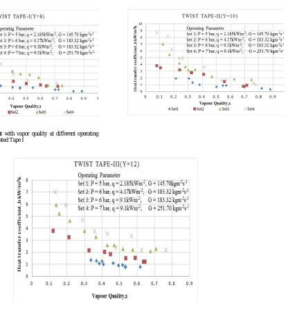
1) Flow boiling heat transfer coefficients at different operating conditions with twisted tape
Figure 3, 4 and 5 shows variation of heat transfer coefficient with vapor quality for twisted tapes I(y=8),II(y=10) &II(y=12) at four operating sets. From figures it can be seen that enhancement in heat transfer coefficient occurs with increasing operating
conditions of pressure, mass flux and heat flux up to 50% vapor quality.
At higher vapor quality, particularly after 60%,it can be observed that heat transfer coefficient values are very close for all twisted tapes at all operating sets. This indicates that there is a less effect of twisted tapes on the improvement of heat transfer coefficient in higher vapor quality region. This means that twisted tapes are effective within lower vapor quality region of 10% to 50%. After 70% vapor quality, heat transfer coefficient values approaches to merge for all operating sets.
Within low vapor quality region nucleate boiling is dominating and the swirl produced due to twisted tape, shakes the mass transfer resistance boundary, which accelerates evaporation rate of low volatile components of R407C.
Hence fast growth in heat transfer coefficient can be observed up to 50% vapor quality with increasing operating conditions for all twisted tapes under investigations.
[image:7.612.38.281.105.259.2]Fig.3Heat transfer coefficient with vapor quality at different operating parameters sets by using Twisted Tape I
[image:7.612.152.419.317.531.2]With increasing vapor quality above 50%, acceleration of two phase flow take place. Flow acceleration and swirl produced due to twisted tape, helps for early transition of current flow in to mist flow. This transition take place around 60% to 70% vapor quality. Hence enhancement in heat transfer coefficient ceases after 70% vapor quality with increasing operating conditions. As a result it can be seen that for all twisted tapes, heat transfer coefficients are approaching to merge at all operating conditions after 70% vapor quality.
For operating set 2&3, with constant conditions of pressure 6 bar and mass flux 183.32 kgm-2s-1,it can be observed that there is a rapid growth in heat transfer coefficient up to 40% vapor quality with increasing heat flux for all twisted tapes. With increasing heat flux at constant pressure and mass flux conditions, nucleation process at the liquid-tube surface speedup, which decreases rate of increase of super heat( i.e. Twall-Tsat)as compare to increase of heat flux. On the other hand induced swirl due to twisted tape avoids
laminar sub layer formation and helps in mingling of liquid components of R407C.Due to these entire conducive surroundings, enhancement in heat transfer coefficient can be seen within low vapor quality region with increasing heat flux for twisted tape I,II III.
On the other hand for operating set 2&3, with constant conditions of pressure 6 bar and mass flux 183.32 kgm-2s
-1
,smallimprovement in heat transfer coefficient can be observed with increasing heat flux, after 70% vapor quality for all twisted tapes under investigations. Hence it can be concluded that maximum effect of increasing heat flux, on heat transfer coefficient improvement due to twisted tapes, can occur within low vapor quality region for R407C.
B. Comparative Performance of Twisted Tape-I,II & III at Operating Set(Conditions):
Figures 3, 4 and 5 mostly talks about the variation of heat transfer coefficient with vapor quality at four operating sets or conditions for each twisted tape. From the analysis of figures 3,4&5, the effective vapor quality region is found out, within which remarkable heat transfer enhancement for all twisted tapes can be seen. However to find the best suitable twisted tape for heat transfer enhancement, all three twisted tapes should be tested on common operating conditions. Out of many testing conditions, most suitable four common operating sets or conditions are selected for comparative performance of twisted tape-I, II and III. Figures 6, 7, 8&9 displays the comparative heat transfer performance of twisted tape I, II &III at four operating sets. From figures 6, 7, 8 &9, it is depicted that the heat transfer performances of all twisted tapes, in each operating conditions or set are very close to each other. However, the performance of twisted tape II&III for operating sets 3 & 4 is seemed to be overlapping for maximum vapor quality range, as seen in figures 8&9.
From figure 6, for operating set 1, twisted tape-III shows maximum heat transfer coefficient values between vapor qualities 30% to 70% as compared to other twisted tapes.
Fig.9 Heat transfer performance of Twisted Tape-I, II&III at operating conditions of P= 7 bar, q= 9.1 kWm-2,G= 251.7 kgm-2s-1
Fig.8 Heat transfer performance of Twisted Tape-I, II&III at operating conditions of P= 6 bar, q= 9.1 kWm-2,G= 183.32 kgm-2s-1
From figure 7, for operating set 2, twisted tape-II is showing best heat transfer performance with maximum heat transfer coefficient values between 20% to 70% vapor qualities. Twisted tape-III shows second best heat transfer performance between 20% to 70% vapor qualities. operating set 3, twisted tape- I is performing continuously better than other two twisted tapes over maximum vapor quality range, as displayed in figure 8.rom figure 9, for operating set 4, a close competition for heat transfer performance can be seen between twisted tape II and III within vapor quality region 20% to 70%. However twisted tape-III is showing performance slightly better than twisted tape-II. Overlapping performance for most of the vapor qualities can be seen for twisted tapes II &III.From figures 6, 7, 8&9, it can be concluded that heat transfer performance of twisted tape depends on its geometry and operating conditions. In general, it can be observed that twisted tape-III with twist ratio, y= 12 is the best heat transfer performer and twisted tape-II with twist ratio, y =10 is the second best heat transfer performer.
V.CONCLUSIONS
Comparative study on heat transfer performance of three twisted tape inserts is carried out during flow boiling of R407C in horizontal copper tube. Conclusions are drawn from following two comparative studies on heat transfer performance of twisted tapes.
A. Twisted tapes are more effective for enhancement of heat transfer within lower vapor quality region of 10% to 50% only.
In general it is found that for all three twisted tapes the improvement in heat transfer coefficient beyond vapor quality 70% is very small for all operating sets.
Induced swirl due to twisted tape help in early transitions of current flow to mist flow after 70% vapor qualities. As an effect improvement in heat transfer coefficient comes to an end after 70% vapor quality for all operating conditions.
B. Use of twisted tapes for heat transfer enhancement is ineffective after 70% vapor quality.
operating set 2 & 3 with constant pressure and mass flux condition, as heat flux increases from 4.17 kWm-2 to 9.1 kWm-2,heat transfer coefficient increases rapidly up to vapor quality of 40% for all three twisted tapes. On the other hand for the same operating conditions of set 2 & 3, at higher vapor quality region, more than 50%, the improvement in heat transfer coefficient with increasing heat flux is seemed to be negligible.
C. Significant effect of heat flux on heat transfer coefficient can be seen within lower vapor quality region only. Conclusions from comparative performance of Twisted Tape-I, II & III at operating set (conditions):
1) Heat transfer performances of all three twisted tapes in each operating conditions are very close to each other
2) For operating set 1 twisted tape shows maximum heat transfer coefficient values.
3) For operating set 2, twisted tape-II is showing best heat transfer performance.
4) For operating set 3, twisted tape- I is performing continuously better than other two twisted tapes.
5) For operating set 4, a close competition for heat transfer performance can be seen between twisted tape II and III.
Second best heat transfer performe In general, heat transfer performance of twisted tape depends on its geometry and operating conditions.
IV.ACKNOWLEDGMENT
Sincere thanks to Government College of Engineering, Aurangabad (India) for financial supports in development of experimental setup under TQIP Phase II.
NOMENCLATURE
A Area, m2 x Vapor quality
d Diameter ,mm Subscripts
D Diameter, mm ev Evaporative
e Enthalpy H Heater
e Enthalpy of liquid i Inner
e Enthalpy of evaporation in Inlet
FSD Full- scale deflection ls Left side
FS Full Scale L Heat Loss, kW
G Mass flux , kgs-1 m-2 o Outer
GWP Global warming potential rs Right side
h Heat transfer coefficient, W m-2k-1 S Surface
ODP Ozone depletion potential sat Saturation
PID Proportional–integral–derivative tp Two phase
q Heat flux, Wm-2 ts Test section
Q Heat ,kW wi Inside wall
t Temperature wo Outside wall
URL Upper Range Limit woz Outside wall location
REFERENCES
[1] Greco, C. Aprea, F. de Rossi, 2000. Experimental evaluation of R22 and R407C evaporative heat transfer coefficients in a vapor compression plant. Int. J. Refrigeration 23, 366- 37
[2] Chi-chuan Wang, Ching-shan Chiang, 1997.Two phase heat transfer characteristics for R-22/R-407C in a 6.5-mm smooth tube. Int. J. Heat and Fluid Flow 18,550-5
[3] T.Y. Choi, Y.J. Kim, M.S. Kim, S.T. Ro, 2000. Evaporation heat transfer of R-32, R-134a, R-32/134a, and R-32/125/134a inside a horizontal smooth tube. Int. J. Heat and Mass Transfer 43, 3651-3660
[4] Aprea, C. Greco, A., 2003, Performance evaluation of R22 and R407C in a vapor compression plant with reciprocating compressor.App.Therm.Engg.23,215-227.
[5] K. N. Agrawal, H. K. Varma and S.Lal, 1986, Heat Transfer During Forced Convection Boiling of R-12 Under Swirl Flow, Journal of Heat Transfer Vol. 108/5 [6] Julio Cesar Passos, Vinicius Fernando Kuser, PhillipeHaberschill, Monique Lallemand, 2003.Convective boiling of R-407C inside horizontal microfin and
plain tubes. Experimental Thermal and Fluid Science 27, 705–713.doi:10.1016/S0894-1777(02)00308-
[7] S.Wellsandt, L.Vamling, 2005. Evaporation of R407C and R410A in a horizontal herringbone microfin tube: heat transfer and pressure drop. Int. J. Refrigeration 28, 901–91
[8] Paisarn Naphon,2006, Effect of coil-wire insert on heat transfer enhancement and pressure drop of the horizontal concentric tubes, International Communications in Heat and Mass Transfer 33,753–763
[9] ShrivastvaRamakant; Kumar Ravi; Gupta Akhilesh; and LalSachidaNand, 2006, "Heat Transfer Augmentation by Inserts During Condensation of Refrigerant R22 Inside a Horizontal Tube". International Refrigeration and Air Conditioning Conference. Paper 850
[10] WaldemarTarganski and Janusz T. Cieslinski,2007, Evaporation of R407C/oil mixtures inside corrugated and micro-fin tubes, Applied Thermal Engineering 27,2226–223
[11] Alberto Garcı, Juan P. Solano, Pedro G. Vicente and Antonio Viedma, 2007, Enhancement of laminar and transitional flow heat transfer in tubes by means of wire coil inserts, International Journal of Heat and Mass Transfer 50,3176–3189
[12] M.A. Akhavan-Behabadi, Ravi Kumar, A. Mohammadpour and M. Jamali-Asthiani,2009, Effect of twisted tape insert on heat transfer and pressure drop in horizontal evaporators for the flow of R-134a, International journal of refrigeration 32,922-93
[13] S. Naga Sarada, A.V. Sita Rama Raju, K. KalyaniRadha, L. Shyam Sunder,2010, Enhancement of heat transfer using varying width twisted tape inserts, International Journal of Engineering, Science and Technology Vol. 2, No. 6, pp. 107-11
[14] P.Rollmann, K.Spindler, H. Muller-Steinhagen, 2011.Heat transfer, pressure drop and flow patterns during flow boiling of R407C in a horizontal microfin tube. J. Heat Mass Transfer 47,951–961.doi:10.1007/s00231-011-0857-
[15] Taye Stephen Mogaji , Fabio Toshio Kanizawa , EnioPedoneBandarraFilho , GherhardtRibatski (2013), Experimental study of the effect of twisted-tape inserts on flow boiling heat transfer enhancement and pressure drop penalty, International Journal of Refrigeration 36,504-515