Design of Press Machine with Automatic
Workpiece Ejection System
Chirag R. Kaladiyil1, Rupesh K. Hatui2
1,2 Department of Mechanical Engineering VIVA Institute of Technology, Mumbai University, Mumbai
Abstract: Press working may be defined as a chip less manufacturing process by which various components are manufactured from sheet metal. This process is also termed as cold stamping. The ram is equipped with a suitable punch and a die block is attached to the bed. A stamping is produced by the downward stroke of the ram when the punch moves towards and into the die block. Various processes like blanking, coining, drawing, punching etc. are performed on the press machine.
Conventional press machine takes more time for loading and unloading of job and for this reason we are transforming from manual ejection system into an automatic ejection system. Considering the current situations there is a need for developing an affordable and simple mechanism for the ejection of workpiece as small scales industry their turnover is totally depended on the quantity of products manufactured. So there is a need for creating a project which would both increase the production and also increase the revenue. This project includes designing a unique system which is simple and affordable to assemble with minimum maintenance. We in this project have designed a mechanical way of ejection of job after press machining. As mechanical engineer our main objective is to optimize the production time, thus making impetus in the production. Our project mainly targets in reducing the production time. It also ensures less human intervention at the machining process. The project of automated ejection system helps to tackle the total production time occurring in the industries. The main ideology of the project is to reduce this non-productive time. We have designed a mechanical way of ejection of job after press machining. It also ensures less human intervention at the machining process. This project of automated ejection system helps to reduce the idle time and also acts as a safety device.
Keywords— press machine, ejection, reduce non-productive time, power press, Ejection system, spring action
I. INTRODUCTION
Sheet metal industry is the global leading manufacturing industries and has great impetus to emerging economy. Manufacturing operations like bending, punching, blanking, coining and drawing are used for manufacturing components from sheet metal. Press working may be defined as, a manufacturing process by which various components are made from sheet metal. This process is also termed as cold stamping. The press machine has ram which is equipped with suiTABLE punch/punches and a die block is attached to the bed. Depending upon the thickness of the sheet metal and the total force required different capacity of press machine are used. Historically, metal was shaped by hand using a hammer. Later, larger hammers were constructed to press more metal at once, or to press thicker materials. Often a smith would employ a helper or apprentice to swing the sledgehammer while the smith concentrated on positioning the workpiece. Adding windmill or steam power yielded still larger hammers such as steam hammers. Drop hammers utilize an electric motor to lift the hammer, which then falls by gravity onto the work. Most modern machine presses use a combination of electric motors and hydraulics to achieve the necessary pressure. Along with the evolution of presses came the evolution of the dies used within them. Hammers were the tool of choice for any Blacksmith, until the turning point in 1784 when a man called James Watt (a Scottish inventor and Mechanical Engineer) described the Steam Hammer. James Watt had a keen interest in steam engines and the mechanics behind it, and his invention of the steam condenser helped other engineers evolve this principle into other industries. Eventually the steam hammer was built in 1840 based on a design by British Inventor James Nasmyth, which was revolutionary and a turning point in manufacturing with steel.
Different press machine are classified based on the source of power are:
A. Fly press
B. Power press
C. Hydraulic press
desired output. Moreover operators or technician perspective the safety measurements also play a keen role for the production process. Press machines used in industries has few flaws in safety while operation. This will create a lot of problem to the operators who have the higher risk to have an accident. This matter creates a lot of problem and at the same time the operators or technician has the higher risk to have an accident in industries. During the production stages the operators tends to get lethargic during the working hours which results in lowering the production and often can cause accidents.
II. METHODOLOGY
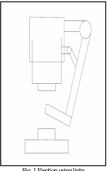
A. Ejection using links
[image:3.612.216.397.242.529.2]In ths system the workpiece would have been ejected by the connected links. The main link is L-shaped where the L-shaped would allow easy ejection of the workpiece. This main link connected to the upper fixed portion. It is free to rotate about the pivot point. A small link is connected to the movable part. Another link is connected to this small link and the main link. It is pivoted at the small link. When the press would have gone up the link would have ejected the workpiece and when the press goes down the link would have been retracted to avoid clashing with the press die.
Fig. 1 Ejection using links
B. Ejection using air blower
In this ejection system the workpiece would have been ejected using an air blower. The sensor would send the signal to the blower to blow out the workpiece after the work is completed and the workpiece would be collected in the collector bin.
1) After the above two mechanism where studied various problems were found. The problems that were identified are: a) The links could get engaged with the upper moving press and this could cause accidents.
b) The metal clips that were manufactured were slightly heavy and hence normal air blowers could not be used.
c) The air blower would have required an extra compressor and this would have increased both the initial cost and maintenance cost.
On solving the above problems a new mechanism was designed and was found to be feasible with the requirements. The mechanism is stated below:
C. Ejection using wedge
Fig. 2 Ejection using wedge
D. Design of Individual component
1) Wedge: A wedge is a triangular shaped tool, and is a portable inclined plane, and one of the six classical simple machines. It can be used to separate two objects or portions of an object, lift up an object, or hold an object in place. Following assumptions are made:
2) Thickness of chamfer on the sliding part of wedge is t1 = 3 mm It is given because it is better than the line contact and it
prevents the design failure.
3) Thickness of upper part of wedge is t = 30 mm
4) Larger height of wedge is l2 = 135 mm
5) Step I: Selection of material
a) The wedges are subjected to tensile force due to its own weight therefore yield strength is the criteria for selection of material for the wedge.
b) The wedges are also subjected to compressive and bending stresses therefore strength is also the criteria of material selection for the wedge.
c) On strength basis the material for two wedges is selected as mild steel.
d) Mild steel is selected as it is easy to manufacture and it can sustain the force for bending the workpiece.
e) Mild steel is easily available material and cost is less as compared to other material.
6) Step II: Calculating the dimension
[image:4.612.149.463.516.713.2]Assuming t = 30 mm
Since ejector leg is to be moved 8 cm backward to prevent collision of upper die with ejector leg. Assuming l2= 135 mm
Since ram to base die height (h) is 180 mm and ram travelling is 50 mm h = l2 + s
= 180 mm l2= 135 mm
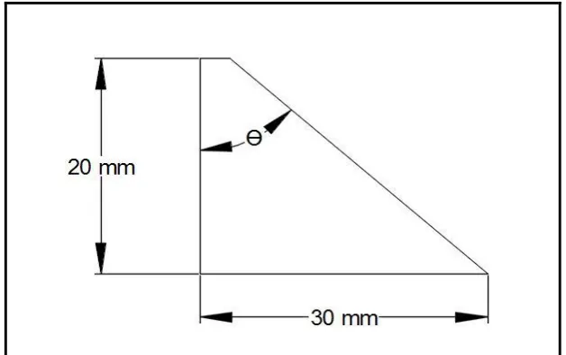
Since height of lower die is 20 mm
Tan θ =
∴θ = tan-1 ( )
= 56.30°
∴ l1= l2 – 2
= 135 -2 = 115 mm
7) Step III: Design of the wedge
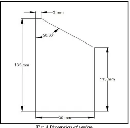
[image:5.612.181.434.313.563.2]All the dimension of the wedge are calculated and the design is shown in Fig. 4
Fig. 4 Dimension of wedge
Spring A spring is an elastic object used to store mechanical energy. Springs are usually made out of spring steel. There are a large number of spring designs in everyday usage the term often refers to coil springs. We are using spring to help ejector leg to push the workpiece. Springs stores ram forces and push back the ejector into original position.
Before starting the design following are the assumptions made: Diameter of spring D= 30 mm
Diameter of spring wire d=3 mm
a) Step I: Selection of material
The springs are subjected to tensile force therefore yield strength is the criteria for selection of material for the spring.
The springs are also subjected to torsional and shear stresses therefore strength is also the criteria of material selection for the spring. On strength basis the material for spring is selected as stainless steel of grade 302.
In stress analysis of spring the effect of stress concentration is neglected. The springs are subjected to cyclic loading
Therefore to account this effect a factor of safety of 2.5 is assumed in the present design.
c) Step III: Calculating permissible stresses
Allowable tensile stress [ ] =
[ ] = = 1164.4 N/
By Maximum shear stress theory [ ] = 0.577 x [ ]
Allowable shear stress [ ] = 0.577 x [ ] = 671.85
d) Step IV: Calculating the dimension
The dimension of the spring is calculated by following procedure. Calculating spring index (C):
C = D/d = 30/3 = 10
Calculation of allowable static load
[τ] =
Where [τ] = Permissible Shear Stress
F = Static load D = diameter of spring k= Wahl stress factor
Assume k= 1 d = diameter of spring wire
[τ] =
∴ F = 237.45 N
Calculating Force exerted on metal clip
The bending force for round tool shape for bending of the metal clip is given by:
F = π x D x t x
Where, D= Diameter of clip t = thickness of clip
= Shear stress of the material
The material of the metal clip is 304L Stainless steel The ultimate yield stress in the metal clip is:
= 172.368
Considering a Factor of safety of 2 as it is a static loading The permissible tensile stress is:
[ ] =
= 86.18 By Maximum shear stress theory
[ ] = 0.577 x [ ]
= 0.5 x 86.18 N/mm2
The thickness of the metal clip is t = 1.5 mm
Therefore the force exerted on the metal clip is given by:
F = π x D x t x
= π x 30 x 1.5 x
= 1483.5 N
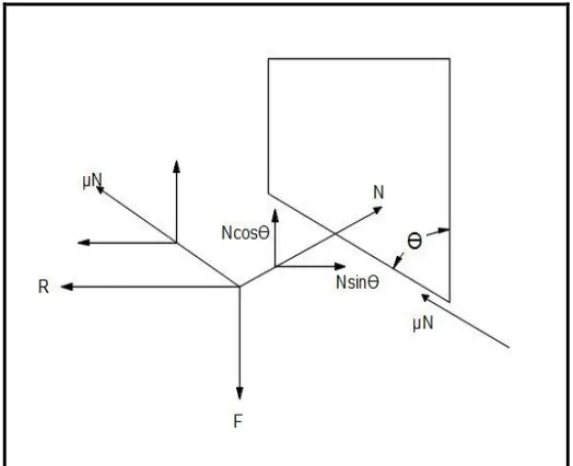
[image:7.612.175.437.257.470.2]Calculating force exerted on spring
Fig. 5 Force resolution By condition of equilibrium
Σ Fx = 0
-N + μNcos (90- θ) + R = 0
∴ R = N – μNcos (90- θ) Σ Fy = 0
Nsinθ – F + μNcos (90- θ) = 0
Nsin56.30 -1370.6 +0.9 x Ncos (90-56.30) =0 N = 905.23 N
R = N – μNcos (90- θ)
R < F = 237.5NSince the force acting on spring is less than the max allowable force
∴Design is safe
e) Calculating Spring Stiffness
K = F/δ
Where, K= Spring stiffness F= Force acting on spring δ = Deflection in spring
Since thickness of wedge is 3cm
∴δ = 3 cm
= 228.379 / (30) = 7.6 N/mm
f) Calculating Solid length (Ls)
Ls =d x n + 2d
Where, d= spring wire diameter n = number of turns
= 3 x 8 + 2 x 3 = 30 mm
g) Calculating Free length:
Lf= P x n + 2d
Where, d= spring wire diameter n = number of turns = 22.8 x 8 + 2 x 3
=188.4 mm = 190 mm
h) Calculating pitch of spring
Pitch of coil = = = 20 mm
Fig.6 Dimension of spring
8) Bottom assembly Bottom assembly is the main frame of our project and its design is of prime importance. It consists of a number of components and their design is as follows.
a) Step I: Selection of material: The wedges are subjected to tensile force due to its own weight therefore yield strength compressive and bending stresses is the criteria for selection of material for the wedge.
Therefore mild steel is selected as a material of two wedges on basis of strength required. Mild steel is easy to manufacture and cost is less as compared to other material.
Mild steel is easily available material
b) Step II: Calculating the dimension Ejector leg lower part
Length of ejector leg lower part, = 25 mm Distance between die is 30 mm giving 2.5 mm clearance on both side to avoid direct contact with walls.
∴ Width of ejector leg lower part, = 95 mm
b1 is decided 95 mm because for pushing the workpiece outside the TABLE ejector leg have to go up to the centre of the TABLE.
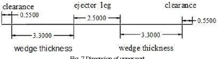
Ejector leg upper part
Fig. 7 Dimension of upper part Length of ejector leg upper part, = 102 mm
As the length between the guide plate is 104 mm because 2 guide plate have to placed and total width is of 220 mm therefore we decided the l2=102 mm
Width of ejector leg upper part, = 30 mm
When ram moves downward direction ejector leg moves to backward direction for proper motion of ejector leg b2= 30mm.
[image:9.612.128.489.532.631.2]Length of guide plate, = 60 mm Width of guide plate, = 30 mm
Length of guide plate is decided because total length is 15 cm and because 2 guide plates have to placed and total width is of 220 mm
10) Upper cover plate
Length of upper cover plate, = 175 mm
Because total length between centers of guide plate is 17.5 cm therefore length cover plate is decided Width of upper cover plate, = 30 mm
Width is decided because ejector moves backward upto 50 mm
11) Back spring support
Length of back spring support plate, = 150 mm Width of back spring support plate, = 25 mm
Length and width of back plate is decided for giving the support to the spring to restore there force proper and moves to original position.
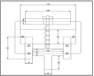
12) Main base plate
[image:10.612.144.472.359.625.2]Length of main plate, L= 150 mm Width of main plate, B= 220 mm Step III: Dimension of Bottom assembly
Fig. 7 Dimension of assembly
E. 3D Modelling Of The Ejector System
A- Back Plate B- Spring
D- Ejector Leg E- Guide Plate F- Upper Wedge
Fig. 8 3D Modelling Of The Ejector System
F. Project Implementation
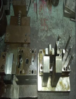
After the above procedures are followed the final project is completely fabricated and is now functional. The following are the actual images of the implemented project.
Fig. 9 Bottom part of the System
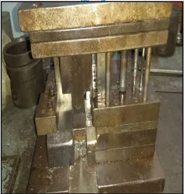
[image:11.612.182.431.387.641.2]Fig. 10 Top part of the system
The Fig. 10 shows the top part of the system. This consists of two wedges connected with the plate which is mounted on the upper die
[image:12.612.174.440.358.704.2]Fig. 12 Assembled view of the system.
G. Construction and Working
An ejector leg is connected to a spring having stiffness k= 7.6 N/mm. On both sides of the ejector leg guide plates are connected which is used to prevent the leg from deviating. The guide plate is fastened to the base plate with the help of fasteners of size M8. A screw is inserted in between the spring to avoid buckling of the spring due to continuous effect. Upper cover plate is connected to the top of the entire assembly to provide extra rigidity. Two wedge slots are cut on the ejector leg where the leg will be pressed back using the upper wedge. This entire assembly is connected with the lower die so as to prevent any alteration to the press machine. The upper assembly consists of only two wedges which are mounted on the upper movable die.
The ejector leg is connected to the spring which in turn is connected to the back plate. When the ram comes down for the power stroke the upper wedge connected to the ram also comes down along with the ram. The upper wedge gets in contact with the slot cutting of the lower ejector leg. The downward force of the upper wedge forces the ejector leg to go in backward direction. This action compresses the spring and the spring stores the energy. When the ram moves back to its original position the spring which has stored the spring energy releases and pushes the ejector leg back to the original position. An extra protruding part is provided in front of the ejector leg which is used to push the workpiece after the operation is performed. This process continues in the cycle and the workpiece is ejected continuously.
III.RESULTS
The data that were collected are formulated into TABLEs and graph and are compared with the system with manual loading and automatic loading. The two different results are recorded and TABLE.
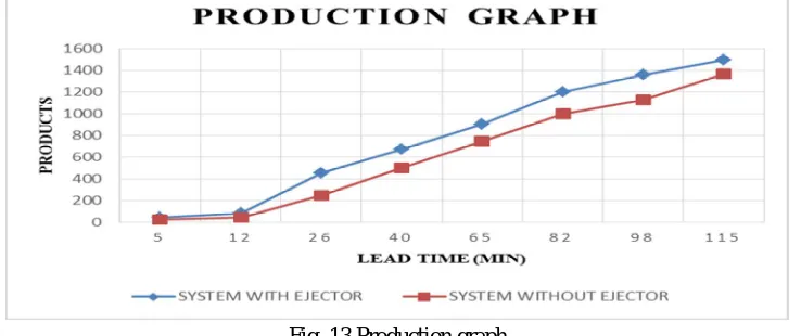
A. Production graph
The production graph has lead time on its x-axis and products on its y-axis. This graph will show the relationship between the products and the time.
B. Profit graph
C. Production chart
TABLE 1
Quantity of products manufactured without the ejector system Time
(Minutes)
Quantity of products manufactured (System without ejector)
5 25
12 50
26 250 40 500 65 750 82 1000
TABLE 2
Quantity of products manufactured with the ejector system Time
(Minutes)
Quantity of products manufactured (System with ejector)
5 45
12 90
[image:14.612.180.434.118.422.2]26 450 40 675 65 900 82 1200
[image:14.612.123.492.435.590.2]Fig. 13 illustrates the graph that are plotted to evaluate the production in each of the cases so as to make necessary comparison.
Fig. 13 Production graph
From the graph it was observed that the system with an ejection system showed slightly higher value of production as compared to the system without the ejection system.
B. Revenue chart
The revenue earned in the month of January and February before the installation of ejection system is recorded and shown in TABLE 3
The revenue earned in the month of January and February before the installation of ejection system is recorded and are shown in TABLE 4
Revenue earned before installing system Month Revenue per m/c
(in rupees) January 50000.00 February 45000.00
TABLE 4
Revenue earned after installing system Month Revenue per m/c
(in rupees) March 58000.00
[image:15.612.97.519.74.476.2]April 54000.00
Fig. 14 Revenue Graph
From the graph it was observed that the system with an ejection system showed slightly higher value of revenue generation as compared to the system without the ejection system.
IV.CONCLUSIONS
Press machine mostly does not come with the automated parts ejection mechanism. Nowadays machine lead time plays a vital role in the production of the industries. Different processes in the press machine already has its lead time of loading and unloading time of the job, increasing it would drastically hampers the total time of production.
The fully automatic ejection system available in the market is costly and has a high maintenance cost. The hydraulic piston arrangement consists of the pump which requires constant maintenance. The hydraulic oil in the system need to be isolated from the surrounding else it can get contaminated and would damage the entire system badly.
The project aim is to reduce the nonproductive time of loading and unloading of job. We have designed a mechanical way of ejection of job after press machining thus making impetus in the production. Our project mainly targets in reducing the lead time. It also ensures less human intervention at the machining process. With using simple and easy to fabricate able materials the maintenance of the overall setup is low. Since there are minimal moving parts, lubrication cost is also less making the desired setup to have higher longevity .The overall safety of the workers is also considered as the primary parameter while designing the mechanism.
and fabrication of the system. The ejection system will be a great boon for the small and medium scale industries. Since industries engaged with the working of the press machine and sheet metal majorly faces the problems associated with the production viz. less work force, human tendency of laziness etc. causing huge loss for the industry. As these industries also faces the [problem of capital crisis. The ejection system developed by us will be more helpful.
The proposed ejection system mechanism solves these issues since this system requires lesser space and low investment which suits the condition for every small scale industry. Use of this mechanism will therefore be very supportive to industries and will increase its throughput and consequently the profit associated with the production.
V. ACKNOWLEDGMENT
I wish to express my gratitude to Dr. Arun Kumar, Principal, Viva Institute of Technology and our guide for his whole hearted support. It gives me immense pleasure to express my deep sense of gratitude and sincere thanks to my mentor and Co-guide Mr. Omkar Joshi, Professor, Viva Institute of Technology, Virar, for help, encouragement and valuable guidance without which this project would not have been possible. His timely advice, meticulous scrutiny, scholarly advice and scientific approach have helped me to a very great extent to accomplish this task.
It is my privilege to thank Professor Niyati Raut, Head of the department of Mechanical engineering for her constant encouragement and support. I owe a deep sense of gratitude to Mr. Varghese Koshy and Mr. Gaurang Nandwana, Professor, Mechanical Engineering for their kind help and co-operation throughout my project.
I wish to express my sincere gratitude to Mr. Pradeep Yande, Proprietor “TRIVENI ENTERPRISE” for providing me an opportunity to do my project work. His prompt inspirations, timely suggestions with kindness, enthusiasm and dynamism have enabled me to complete my task.
I also wish to express my indebtedness to my parents for their blessings and for being my constant motivation which always helped me to face the challenges ahead. I owe a lot to my friends who have been instrumental for providing me necessary technical suggestions during my project pursuit. Last but not the least, I am thankful to all those who directly or indirectly helped me in completion of this project report.
REFERENCES
[1] P.DEVENDRAN, R.SAMBASIVAM,“ MODELLING AND ANALYSIS OF CORRUGATED SHEET METAL BENDING PROCESS”, IJIRSET,2017.
[2] NITESH A. MESHRAM, MANISHKUMAR J. SAINI,“MODELLING AND SIMULATION OF SERVO MECHANISM FOR PUNCH PRESS”, IJERT, VOL.5 ISSUE 07, ISSN: 2278-0181,2016.
[3] RAJDIPSINH G VAGHELA, RAVI C PATEL, KANAKSINH GOHIL,“A REVIEW ON DESIGN & ANALYSIS OF C-FRAME OF PNEUMATIC POWER PRESS USING FEA”, IJSRD, 2016.
[4] DEEPAK ANNASAHEB MORE, N.K. CHHAPKHANE, RAVINDRA KOLHE,“DESIGN, DEVELOPMENT AND OPTIMIZATION OF HYDRAULIC PRESS”, IJRASET, VOLUME 3,
ISSUE VI,2016.
[5] AMEET B. HATAPAKKI, U D. GULHANE,"DESIGN OPTIMIZATION OF C FRAME OF HYDRAULIC PRESS MACHINE ", INTERNATIONAL JOURNAL OF ENGINEERING DEVELOPMENT AND RESEARCH (IJEDR), VOLUME 3, ISSUE 2, ISSN:2321-9939,2015.
[6] NIKHIL MAHAJAN, S. B. TULJAPURE,“FINITE ELEMENT ANALYSIS OF A 2.5 TONNE HYDRAULIC PUNCHING MACHINE”, IJSDR, VOLUME 1, ISSUE 3, ISSN:2455-2631, 2016.
[7] A. G. NAIK, N. K. MANDAVGADE,“FEA IMPLEMENTATION IN ANALYSIS AND OPTIMIZATION OF TOP AND BOTTOM FRAME FOR HYDRAULIC COTTON LINT BAILING PRESS”, INTERNATIONAL JOURNAL OF SCIENTIFIC & ENGINEERING RESEARCH VOLUME 3, ISSUE 7,2016.
[8] M.ARUNKUMAR, V.MUNUSAMI, R.KARTHIK, V.ASHOK KUMAR,“DESIGN AND ANALYSIS OF A SPRING BACK EFFECT IN SHEETMETAL FORMING”, INTERNATIONAL JOURNAL OF RESEARCH IN ENGINEERING & ADVANCED TECHNOLOGY, VOLUME 4, ISSUE 2,2016.
[9] MOHAMMAD ISRAR, AMIT TIWARI, ANSHUL GANGELE ,“DESIGN & OPTIMIZATION OF POWER PRESS MACHINE”, IJETI, VOL.2, ISSUE 01,2015.
[10] MUSTAFA TELWALA, ANAND PARIKH,VAJA HITESH, HARDIKBHAI DABHI, RAJDIPSINH. G. VAGHELA, HARDIK N. CHAUHAN ,”A REVIEW ON COST OPTIMIZATION OF POWER PRESS BY ANALYSIS OF C-FRAME USING SOLID WORKS”, JETIR,2015.
[11] RANGRAJ S. MORE, SHREENIDHI R KULKARNI,“FINITE ELEMENT ANALYSIS AND OPTIMIZATION OF C TYPE HYDRAULIC 200 TON PRESS”, INTERNATIONAL RESEARCH JOURNAL OF ENGINEERING AND TECHNOLOGIES , VOL.2, ISSUE 3, PP.1385-1391,2015.
[12] ANDREAS WALTHER, HERBERT FUCHS, SIMON BENJAMIN WALTHER, JÜRG OCHSENBEIN,“DEVICE FOR REMOVING PRECISION PUNCHING RESPECTIVELY FINE BLANKING PARTS FROM A TOOL OF A PRESS”, PATENT US 12/960,054,2014.
[13] N. M. Z. HASHIM1, N. M. T. N. IBRAHIM, Z. ZAKARIA, FADHLI SYAHRIAL, H. BAKRI,“DEVELOPMENT NEW PRESS MACHINE USING PROGRAMMABLE LOGIC CONTROLLER”, IJECS, VOLUME 2 ISSUE 8,2013.
[15] VIJAYLAXMI G.BIRADAR, SIDDHARAM PATIL , R M LATHE,“AUTOMATION OF SHEET BENDING MACHINE USING ELECTRO PNEUMATIC DEVICES”, IJSER, VOLUME 3,
ISSUE 9 ISSN 2229-5518,2012.
[16] JEFFREY CLARK, WILLIAM FRANK, PHILLIP ICKES,“WORKPIECE HANDLING SYSTEM WITH GEOSTATIONARY EJECTION FUNCTION”, PATENT US 20060120850 A1, 2006.
[17] MICHAEL LEVIN, LEV TSYGAN,“PRESS SIMULATION APPARATUS”, PATENT US 6106262 A,2000.
[18] GAROLD W. ALEXANDER, JOE L. FORTNEY,“APPARATUS FOR RELEASING A PRESS-FORMED ARTICLE FROM A DIE SET”, PATENT US 4755128 A,1988. [19] FRANZ STEHR,“DIE EJECTOR ASSEMBLY FOR MULTI-STAGE FORMING MACHINES”, PATENT- US 4552525 A,1985.
[20] LOUIS F. CARRIERI, GULF & WESTERN MANUFACTURING COMPANY,“WORK PIECE EJECTOR SYSTEM FOR PRESSES”, PATENT- US 4370878A,1981. [21] LOUIS F. CARRIERI, GULF & WESTERN MANUFACTURING COMPANY,“CAM ACTUATED EJECTOR MECHANISMS FOR PRESSES”, PATENT- US 4068520 A,1978. [22] FRANK MARTINDELL, FERRACUTE MACHINE COMPANY,“WORK-PIECE EJECTOR FOR COINING PRESSES”, PATENT- US 3053122A,1962.
[23] ANKIT H PARMAR1, KINNARRAJ P ZALA, ANKIT R PATEL,“DESIGN AND MODIFICATION OF FOREMOST ELEMENT OF HYDRAULIC PRESS MACHINE”, INTERNATIONAL JOURNAL OF ADVANCED SCIENTIFIC AND TECHNICAL RESEARCH,