http://dx.doi.org/10.4236/jpee.2014.24036
IEEE1588 Time Synchronizing System
Multiplexing Industrial Ethernet of
Distribution Automation
Shuwei Feng1, Meiyi Hou1, Guofang Zhu1, Qi Qi1, Richang Xian2, Tao Jiang2, Ying Zhai2,
Ming Sun2
1College of Electrical Engineering, Shandong University, Jinan, China 2Zibo Power Supply Company, Zibo, China
Email: [email protected]
Received December 2013
Abstract
The present study explores an IEEE1588 Synchronizing System for smart distribution grid based on Industrial Ethernet. The paper first analyzes the communication system in distribution net-work and then proposed the project of time synchronizing system using IEEE1588 in distribution network. The study focuses on rational clock correcting time region segmentation, selecting the best clock source injection point and multiple redundant methods when correcting time method lose efficacy, etc. The precision of time synchronizing is better than that of 1 millisecond.
Keywords
IEEE1588; Distribution Network; Communication Network; Industrial Ethernet; Time Synchronization
1. Introduction
Time Synchronizing System of power network is an important system that standard clock source message trans-fers step-by-step through each node in communication network, synchronizing their time to make the power grid to realize various functions. The various service functions of power grid have different levels for the demands of time synchronization precision, namely, the requirement of Electricity Acquisition, Load Control and Power Consumption Management in time-precision reaching up to 1 second, measucontrol system of SCADA re-quiring precision of 10 ms, Sequence records of SOE rere-quiring precision of 1ms, line traveling wave fault loca-tion, lightning localoca-tion, Phasor Measurement Unit PMU and etc. requiring precision of 1 microsecond [1,2].
Distribution Grid wide-area protection and Event Management, Smart Distribution Grid Seamless Self-Healing etc. The time precision of distribution network must reach the microsecond level [3,4]. Therefore, our research on the construction of Smart Distribution Grid precise time synchronization system is of great significance.
The current researches on time synchronization of electric power system mainly focus on the substation au-tomation, which use following technologies: GPS time setting, pulses per second time setting, IRIG-B code, Simple Net Time Protocol SNTP, Precise Time Synchronization Protocol PTP et al. [5-7]. Among them, GPS has the highest synchronous precision, but it is expensive and not suitable for application in a large number of nodes of distribution network. Besides, its stability and safety is also not very reliable, pulses per second and IRIG-B coding synchronization have also achieved a relatively high precision. However, they need an extra time setting special line, which fails in being used in the distributed system as distribution network that has larger span length; The SNTP network message’s synchronous precision can only reach ms level.
IEEE1588 is also called precise time synchronization protocol PTP of distributed control and measurement system, which by virtue of correcting time message bag and playing time stamp in the bottom to achieve the mi-crosecond time synchronization network precision in Ethernet [8,9]. This protocol can multiplex Ethernet com-munication network, with low resource usage and with no need for laying extra lines; can reduce the cost of system construction. Currently, researches in IEEE1588's application in power system mostly concentrate in the substation automation. However, the application of power distribution network is still in its infancy. There are a large number of mature switch products made in both domestic and foreign manufacturers support IEEE1588 protocol.
Owning to the high capacity bandwidth, strong anti-interference ability, relatively low cost, low bit error rate, high rate and good security, optical fiber communication become the first-choice technology of the distribution network communication system [10-12]. With the proliferation of IP business, fiber optic Ethernet technology gradually becomes the preferred technology in backbone layer and access layer of power distribution network communication system. The scheme that with gigabit Etherring network to build distribution automation back bone network, with 100 m industrial Ethernet ring network to build distribution automation access network has become the typical scheme to construct automate communication system of distribution network. This paper is based on this typical scheme; studies a correcting time system using IEEE15888 multiplexing optical Ethernet technology in distribution network communication system.
This paper firstly introduces the typical scheme of distribution network communication system; and then put forward the objectives and principles to construct IEEE1588 time correcting system of distribution network communication system. We have made a study on IEEE1588 correcting time region segmentation method which is adapt to typical communication topology, the best clock source injection scheme and several multiple redun-dant means when correcting time methods failures. The work of this paper laid a solid foundation for the appli-cation of IEEE1588 in intelligent distribution network.
2. Typical Topology of Distribution Network Communication System Based on
Industrial Ethernet
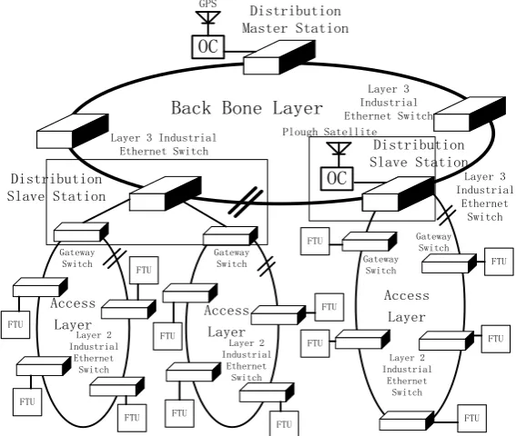
The networking mode of industrial Ethernet is flexible, which can be framed as single fiber type, double fiber type, chain type, star type, tree type, ring type, multi-branch on ring type and so on. The latest communication topology planned by State Grid Corporation must meet the requirement of optical cable line N-2 protection and node equipment N-1 protection, so the development and transformation trend of future communication network is from line to ring, then from ring to net, And the distant site needs redundant double-lined links. According to the principle that communication network should be adjacent to primary feed line and cover every node of pri-mary line. Meanwhile, taking many factors in to consideration, such as the cost saving, simple construction wir-ing, clear network topology hierarchy and whether which can meet certain line redundancy and convenient management, Ring topology is a reasonable choice of distribution automation system. Figure 1 shows the typi-cal topology of l distribution network communication system based on industrial Ethernet.
Redundant topology management protocol, such as Rapid spanning tree protocol, can block some links, au-tomatically forming a logically communication topology tree to prevent circuits existed in network forming broadcast storm.
Figure 1. Typical topology of distribution network communication system based on industrial Ethernet.
backbone layer, the backbone network uses three industrial Ethernet switches and forms a ring network through gigabit optical to enable dynamic routing protocol in the ring network, then achieves the data routing dynamic transition. Access layer is mainly used for 10 kV distribution network terminal access at all levels, covering each open-close station, ring network cabinet, distribution station, pole top unit , etc.
Access layer is composed by industrial Ethernet switches in the region covered by each communication con-vergence point, which is divided into different corresponding sub-rings. According to the scope of the area cov-erage, this ring can be divided into two kinds of structures: one kind is the Tangent Access Ring structure, in which layer 2 industrial Ethernet switches form ring network through 100 m fiber optic port, access to the layer 3 switch of the backbone network of local communication convergence point by layer 2 switch. This structure is generally applicable to the layer 2 switch using private ring protection protocol.
The protection switching time of access ring of which can be reached within 20 ms; the other structure is the Direct Connection Access Ring, two ends of which access to the layer 3 switch of the backbone network of local communication convergence point by two gateway switches respectively.
3. Correcting Time Network of Unified Distribution Network Based on IEEE1588
3.1. The Overall Construction ObjectiveThe construction objective of this paper is to use IEEE1588 technology, multiplexing industrial Ethernet com-munication system, through rational Layering of correcting time system, rational selection of clock node type, eventually to form a wide-area multilayer correcting time network of unified distribution network, which can cover all the distribution automation terminal nodes, takes higher level or local station precise clock source as master clock, has a variety of clock source reserves, can transfer precise clock step by step, forms new clock tree automatically when network redundancy switches, whose precision is better than that of 1 millisecond and has good divergence, so as to serve for the construction of Smart Distribution Grid wide area measurement and con-trol system.
3.2. Construction Principles of Unified Correcting Time Network
• Rational correcting time system layered, to achieve a high effect that the scale expansion degree of correct-ing time network.
OC
OC
FTU
FTU
FTU FTU
FTU
FTU
FTU FTU Back Bone Layer
Plough Satellite GPS
Layer 3 Industrial Ethernet Switch Distribution
Master Station
Distribution Slave Station
FTU
FTU
FTU
FTU Layer 2
Industrial Ethernet
Switch Gateway
Switch Access
Layer
FTU Layer 3 Industrial
Ethernet Switch Layer 3 Industrial
Ethernet Switch Distribution
Slave Station
Access Layer Access
Layer
Gateway Switch Gateway
Switch Gateway
Switch
Layer 2 Industrial
Ethernet Switch Layer 2
Industrial Ethernet
• Rational select time node type to achieve the effect of less correcting time layer levels, smaller accumulated error and rational line and node load.
• A variety of clock sources reserved to enhance the robustness of system.
• Select rational clock source injection point to enable the whole system save a lot of GPS correcting time equipment.
• To prioritize the different clock sources, higher level communication node clock course are set to level 1, the main station clock source for the secondary, sub-station clock source is set to level 3.
• If Time Islands appear in access layer, a unified clock should be established for the time islands so as to re-duce the impact as much as possible.
4. Using Reasonable Clock Correcting Time Region Segmentation to Form a
Wide-Area Multi-Layer Unified Correcting Time System
We can see from Figure 1, typical topology of distribution network communication system based on industrial Ethernet can be abstracted as the structure that bid ring of back bone layer tangent to multiple small rings of access layer.
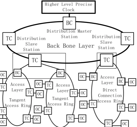
This paper also uses layered principle, considers every communication ring (Including the big ring of back bone layer and the small ring of the access layer) as a clock correcting time region and sets one switch node clock type configuration as BC in every clock correcting time region, which would be the master clock in this clock correcting time region; While Other node configurations are set as TC so that we can achieve the effect of less system correcting time layer levels, smaller accumulation error as well as proper line and node load.
In the big ring of back bone layer, we select the main switch node to be defined as the gateway switch in this layer, the clock type of which is set as BC, while other nodes are set as TC (P2P model). In the small ring of access layer, we select the gateway switch (every Tangent Access Ring has a gateway switch; the Direct Con-nection Access Ring has two gateway switches) as BC, while other switch nodes as TC (P2P model). The main Station switch receives higher network precise clock or GPS precise clock source message, to correct the time of local clock of this node. The station back bone switch sets local clock as master clock, which sending message to other switches connected to back bone network.
Because they are set to TC, which are not involved in correcting time themselves, when the master clock port sending correcting time message through TC to the next TC or the gateway switch of access layer connected to it, In this layer, all the gateway switches of access layer can complete a time synchronization at the end of a cor-recting time cycle. After all the gateway switches of access layer complete time synchronization, each of which then as the master clock itself, sends correcting time message to other connected switches or distribution termin-al equipment of itself, the correcting time message passes through the connected TC to reach the next TC or the connected distribution terminal equipment. Clock correcting time region segmentation and node configuration are as shown in Figure 2. According to the segmentation and configuration mode a wide-area multi-layer uni-fied correcting time network can be formed.
BC node is the boundary of segment PTP correcting time sub-domain, which can form PTP sub-domain that is well-organized, Multiple distinct, relatively independent and has simple time setting process. In the PTP sub- domain, one layer is time-corrected by the upper layer and so on, finally a clock correcting time tree system is can be formed.
Generally the Sync message sending cycle of every PTP sub-domain is 2 seconds, in which the local clock error will gradually accumulate, until the next update. While the next layer will plus the 2-seconds accumulate error of the upper layer to the local 2-seconds local accumulate error. Therefore, there are the more layer levels, the more accumulative errors.
Gateway switch is equivalent to a gateway of clock message flow, the ring network and the joint of higher and lower network are both guarded by a gateway switch, which is set as BC, making the correcting time system of one layer separated from that of the upper and lower layer, forming the relatively independent PTP sub- do-main.
The time stamp of ever layer level is as a big correcting time system, broadcasting correcting time message bag through the gateway switch BC of this layer, all the correcting time message can be sent to every timing node of this layer though TC without error accumulation.
Figure 2. Wide-area multilayer correcting time network of unified distribution network.
ease the communication load of the lines and equipment, improve the stability of the correcting time system. If we segment clock correcting time region according to this method, the correcting time message of back bone layer in counties can transfer to the terminal equipment of its 10 KV distribution network access layer. Just through two layer PTP correcting time domains. So not only the correcting time error can be controlled in min-imum range, but also an arbitrary extensional, wide-area multi-layer unified correcting time network is formed.
Setting all the TC as P2P transparent clock is designed to further reduce the communication load of line and equipment. when P2P, path delay jitter between adjacent equipment are all recoded in node by fixed-cycle tim-ing measurement, when the time stamp message sent by the master clocks arrive to the slave clocks, all the path delay jitters and switch protocol stack jitters are added into the master clock message, the slave clocks Only need according to the local time of received Sync message, Can accurately calculate the time error of the master clocks to adjust themselves, without sending Delay-Request, Delay-Response and so on. It is Equivalent to that a master clock sends correcting time message one- way to slave clock, no longer with method of table tennis.
While E2E transparent clock still measure s path delay jitter with a ping-pong method, and when the network topology changes (protection switching), transient and larger deviation may occur in the synchronous precision of E2E transparent clock, which may lead to the protection misoperation of protection device.
5. The Implementation Scheme of Strong Correcting Time Network of
Distribution Network
5.1. The Realization of Injection and Redundancy of Back Bone Layer Clock Source
The maser clock of the correcting time network of this layer is the communication interface of the gateway switch to connect higher level back bone network, which receives precise clock of higher network, synchronizes the local clock of the switch, then broadcasts correcting time to all the BC connected to the correcting time net-work of this layer. Reserve clock sources the GPS SATELLITE synchronization equipment connected to the gateway switch and GPS SATELLITE synchronization equipment the Plough Satellite synchronization equip-ment connected to other sub-station back bone switches of this layer. The priority of clock source is, in order, higher network precise clock, GPS equipment of gateway switch, the Plough Satellite equipment of sub-station back bone switch and local clock. When master clock fails, the node automatically updates to switch to second-ary reserve clock source through BMC algorithm and makes it become the new master clock, so as to form a new correcting time tree. The back bone ring makes it in graphic logic link disconnected and form a dendritic correcting time system.
The correcting time network in the scheme doesn’t need that each station at counties is equipped with GPS
Distribution Slave Station BC TC TC TC TC BC BC TC TC TC TC TC TC TC TC OC OC OC OC OC OC OC OC
Higher Level Precise Clock
Distribution Master Station
Back Bone Layer
[image:5.595.203.428.86.294.2]time setting equipment. Only with one set of GPS and one set of Plough Satellite we can achieve N-2 level re-dundancy of the clock source in backbone layer, which greatly reduces the cost of the correcting time system. When the communication ring malfunctions, through protection switching mechanism, the original logical breaks and the new communication line generates, the ring structure makes the transmission direction of original data invert, at this point, because the switches are all TC, his node does not participate in freshly generated syn-chronization tree.
What is just needed is to automatically adjust the P2P remeasures the adjacent path delay jitter at the change of the connection.
5.2. The Realization Scheme of Injection and Redundancy of Back Access Layer Clock Source
When the communication network is Tangent Access Ring, the master clock of the correcting time network of this layer is the communication interface of the gateway switch in sub-station to connect higher level back bone network, which receives precise clock of higher network, synchronizes the local clock of the switch, then broadcasts correcting time to all the terminals connected to the correcting time network of this layer. If the sub-net fails to receive precise clock of higher sub-network, a time Island will be formed, at this point, because the gate-way switch is set as BC, it will become the master clock of this Time Island through BMC algorithm, which makes the clocks of all the nodes in the whole sub-net relatively synchronous. Other mechanism is similar to the backbone layer.
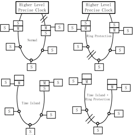
[image:6.595.201.427.463.692.2]When the communication network is Direct Connection Access Ring, the ring breaks at the logic shown in
Figure 3, which sets two gateway switches as BC, the priority of one gateway switch is higher than the other (set high on the left), in this way, The formation of time synchronization tree will be more convenient, to avoid correcting time conflicts.
At Normal state, the higher network send a precise clock to the left gateway switch, which then sends precise clock to all the OC and the right gateway switch. When there is ring protection in line, the higher network send s precise clock respectively to the gateway switches on both sides, which then send the clock to the PTP sub- do-mains they respectively connected. When there is a time island, the left gateway switch will send clock to all the OC and the right gateway switch as the master clock. When there are time islands and ring protection in the meantime, which is equivalent to two time islands, in each time-island the gateway switch will be the mater clock source to correct time.
Figure 3. Four kinds of synchronization trees of direct con-nection access ring.
Higher Level Precise Clock
S
M M
S
S S
S S
S
M M
S
S S
S S
S
S
M SM
S
S
S S
S
Normal
Ring Protection
Time Island + Ring Protection Time Island
M
M S
S
S S
6. Conclusions
In this paper, the multiplexing scheme of IEEE1588 technology in industrial Ethernet distribution network communication system is discussed and analyzed through rational Layering of correcting time system, rational selection of clock node type, finally, we constructed a strong wide-area multilayer correcting time network of unified distribution network, which covers all the distribution automation terminal nodes, whose precision is better than that of 1 millisecond and has good divergence of correcting time scale.
Currently there are still a lot of back bone layer communication networks are for SDH/MSTP, because the SDH network has its own unique time synchronization system, so you can put the whole clock BC, SDH net-work as a boundary clock BC, at the joint of which connected to the Ethernet, we can solve the problem of transmission compatibility of IEEE1588 protocol with a protocol converter. With the scheme of this paper, the access layer can achieve the construction of correcting time system that not only the back bone layer is SDH/ MSTP but also the access layer is switch ring network.
References
[1] Yu, Y.H., Zhang, D.N., Hu, Y.H., et al. (2008) Time Synchronizing System for Power System. Automation of Electric Power Systems, 32, 82-86.
[2] Hu, J. and Gao, X.H. (2009) Application of SNTP-Based Time Synchronization in Digital Substation. Electric Power Automation Equipment, 29, 143-148.
[3] Zhu, G.F. and Lu, Y.P. (2010) PPS Synchronization Based on RPR for Digital Substation. Electric Power Automation Equipment, 30, 90-94.
[4] Liu, H.Y., Hao, H.T., Li, Y.X., et al. (2009) Research on a Synchronism Scheme for Digital Substations. Automation of Electric Power Systems, 33, 55-58.
[5] Sun, X.X. (2010) Application of xPON and Industrial Ethernet Technology in the Distribution Networks. North China Electric Power University, Beijing.
[6] IEEE Instrumentation and Measurement Society (2008) IEEE1588TM v2.2 Standard for a Precision Clock Synchroni-zation Protocol for Networked Measurement and Control Systems. IEEE, New York.
[7] John, C. (2006) IEEE-1588 Standard Version 2-A Tutorial. Agilent Technologies, Palo Alto.
[8] Yu, Z.L. and Li, Z. (2009) Best Master Clock Algorithm of Precision Clock Synchronization Protocol. Electric Power Automation Equipment, 29, 74-77.
[9] Yu, P.F., Yu, Q., Deng, H., et al. (2009) The Research of Precision Time Protocol IEEE1588. Automation of Electric Power Systems, 33, 99-103.
[10] Zhao, S.L., Hu, M.Q., Dou, X.B., et al. (2008) Research of Time Synchronization in Digital Substation Based on IEEE1588. Power System Technology, 32, 97-102.
[11] Xie, L., Huang, G.F. and Shen, J. (2009) Design of High Accuracy Synchronous Sampling Clock in Digital Substations.
Automation of Electric Power Systems, 33, 61-65.