Multiplier-less Farrow Structure Based Linear Phase
Low Pass Interpolation Filter
Nisha Haridas
Department of ECENational Institute of Technology Calicut Kerala, India-673601
Aravind Illa
Department of ECENational Institute of Technology Calicut Kerala, India-673601
Elizabeth Elias, Ph.D
Department of ECENational Institute of Technology Calicut Kerala, India-673601
ABSTRACT
This paper proposes a totally multiplier-less farrow structure based linear phase low-pass interpolation filter. When implemented us-ing farrow structure, it has inherently low number of multipliers and adders compared to that using finite impulse response (FIR) filter structure. To further reduce the implementation complexity, the structure is made totally multiplier-less. Canonic signed digit (CSD) representation of the filter coefficients is made use of in this paper. A meta-heuristic optimization algorithm is deployed to ob-tain optimal CSD representation. Reduction in the implementation complexity leads to lower power consumption, chip area and cost.
Keywords:
Farrow, Interpolation Filter, Integer Sampling rate conversion, ABC optimization, Canonic Signed Digit
1. INTRODUCTION
Reduction of hardware complexity is highly important in a digital system. In communication and other digital signal procesing (DSP) systems, the major contribution to complexity is due to multipliers. Omnipresence of multiplications in these systems increases the requirements for silicon area (or hardware resources in case of FPGA), clock speed and power consumption. Overall speed of a system is often limited by that of its multipliers. The solution then is to replace the multipliers and reallocate the function to alternate low cost elements such as adders and shifts. The shifts can be implemented as wired shifts, thus reducing silicon area overhead also.
An interpolation (decimation) filter is a linear phase filter used along with an upsampler(downsampler). It has been shown by Johannson,et al. [1], that a low complexity interpolator can be designed using farrow structure [2]. Modified farrow structure[3] has been proved efficient for implementing rational sampling rate conversion (SRC) [4, 3]. In [1], an integer SRC is described and is proved to possess lower complexity for higher interpolation factor. Here, the low pass filter has been designed by decomposing it to polyphase components, and each of them, except the first, realized using farrow subfilters, with a distinct fractional delay. This approach has an advantage over single stage FIR based interpolation filters in terms of complexity (multipliers), especially
at high interpolation factors. Also, the structure is flexible as to the conversion factors. When the conversion factor is changed, it can be implemented by changing the set of fractional delay coefficients alone and using the same set of subfilters. Thus, such filters are efficient reconfigurable converters. In particular, they can simultaneously implement several converters at a low cost. The same method was later extended to implement interpolators and decimators using bandpass filter [5]. Reconfigurability and low-complexity due to farrow structure has been proved in literature [6, 7].
In this paper, further reduction in complexity is achieved by proposing a totally multiplier-less implementation for the interpo-lator. This reduction in the complexity is achieved by expressing the coefficients under consideration using Canonic Signed Digit (CSD) representation. Direct Approximation of the coefficients to CSD can cause degradation of filter performances. This can be overcome by optimizing the coefficient values such that the aver-age number of adders and required specifications are maintained.
Meta-Heuristic algorithms are proved to be good choices, in this regard [8], to improve the CSD converted interpolation filter with less complexity. In this paper, Artificial Bee Colony (ABC) optimization algorithm is used. Such an approach to obtain a multiplier-less realization of the interpolation filter using farrow structure is not reported in the literature so far.
Section 2 gives a brief on modified farrow structure and its implementation as interpolation filter. Multiplier-less design is discussed in section 3. ABC Algorithm is briefed in Section 4. Section 5 describes the proposed design. In Section 6, the results are discussed and the conclusions are presented in Section 7.
2. FARROW STRUCTURE
Fig. 1: Modified Farrow Structure
2.1 Modified Farrow Structure
This structure is a modification of the original Farrow structure [3]. The overall filter is a linear combination of linear-phase finite-impulse response (FIR) subfilters Gk(z) weighted with dk as
shown in Figure 1. When d is fixed, the overall filter approximates an all-pass filter with the fractional delay d, provided that the sub-filters have been designed in a proper manner [1, 3]. The major advantage of using the Farrow structure is that the subfilters do not have to be redesigned when a new fractional delay is desired but just the value of d has to be adjusted. Filters with adjustable frac-tional delays are required in several applications such as sampling rate conversion by arbitrary conversion factors, which traditionally requires high interpolation and decimation factors[1].
2.2 Modified Farrow Structure based Interpolation Filter
In addition to being attractive for sampling rate conversion by arbi-trary conversion factors, the Farrow structure can in fact also be uti-lized to obtain efficient (low-complexity) converters for sampling rate changes by integer factors[1]. Overall Transfer function of a filter H(z)in polyphase form is given by,
H(z) =
M−1
X
m=0
[z−mH
m(zM)] (1)
When H(z) is a linear phase interpolation or decimation low pass filter, it can be approximated as,
H(z) =
(
z−N/2, ωT ∈[−π/M, π/M]
0, ωT ∈[−π,−π/M]∪ [π/M, π] (2)
This is achieved by requiring that the delay of eachz−mH m(z)
approximatesz−N/2 in the region[−π/M, π/M].H
m(z)are the
M−1polyphase components.This requirement can be stated dif-ferently as,
Hm(z) =z−(N/2−m)/M, ωT∈[−π, π] (3)
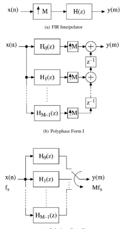
The polyphase structure of H(z) when it is used as an interpolation filter is shown in Figure 2.
A decimator can be obtained from the interpolator by reversing the signal flow graph and replacing the upsamplers by downsamplers. As proposed in [1],H0(z)as shown in Figure 2(b) is anN0thorder
Type I linear-phase FIR filter, such that the overall lowpass filter (LPF) order,
N =N0M (4)
(a) FIR Interpolator
(b) Polyphase Form I
[image:2.595.67.280.73.154.2](c) Polyphase Form II
Fig. 2: Single stage FIR interpolator and its polyphase decomposed forms
The remaining filters are realized using the modified Farrow struc-ture,
Hm(z) = L
X
k=0
dk
mGk(z), m= 1,2...M−1 (5)
wheredmare the fractional-delay coefficients andGk(z)are
lin-ear phase FIR filters,N1 odd/even order with symmetric or
anti-symmetric impulse response. From (5),Hm(z) approximates an
allpass filter with the fractional delayN1/2 +dm. Using (3) and
(4) and choosingN0=N1+ 1,
N1/2 +dm= (N/2−m)/M ⇒dm=−m/M+ 1/2 (6)
This shows thatdmexhibits antisymmety and this can reduce their
implementation cost by a factor of two.
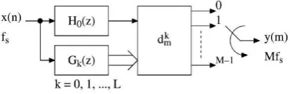
Fig. 3: Final Interpolator structure using Farrow subfilters
[image:3.595.74.281.70.137.2]Hence, the polyphase representation of interpolators and decima-tors can generally be realized using the structure given in Figure 3. This implementation leads to lower structural complexity com-pared to that of a single stage interpolator shown in Figure 2(a). Number of multipliers in each case is calculated as in Table 1.
Table 1. : Complexity Calculation
FIR N/2; N even N+ 1/2; N odd
Farrow N1+ 3/2 + (L+ 1)(N1+ 1)/2 +L(M−1)/2; M odd N1+ 3/2 + (L+ 1)(N1+ 1)/2 +L(M−2)/2;M even
3. MULTIPLIERLESS IMPLEMENTATION OF THE INTERPOLATOR
The interpolator filter can be made multiplier-less for efficient hard-ware implementation
3.1 Canonic Signed Digit Representation
If the filter coefficients are represented in the signed power of two (SPT) space, the multipliers in the filter realization can be replaced with adders and shifters. The canonic signed digit (CSD) repre-sentation is a unique reprerepre-sentation of the decimal number with minimum number of non-zero bits. When the filter coefficients are represented in the CSD space, the number of partial product ad-ditions reduces. Any number d can be represented using the CSD format as follows:
d=
W
X
i=1
bi2R−i (8)
where, W is the word length of the CSD number and integer R represents a radix point in the range0< R < W.
4. OPTIMIZATION TECHNIQUES
Conversion of the design to CSD space may create deviation from the required specifications. Here, the lowpass filter characteristics such as passband ripple and stopband attenuation may degrade. First, the interpolation filter is made multiplier-less and then opti-mized to regain the degraded parameters. Classical gradient based optimization techniques cannot be used since the search space con-tains integers. Meta-heuristic algorithms are good choices here [8, 9]. In this paper, Artificial Bee Colony (ABC) Algorithm is used and performance is discussed.
4.1 Optimization using Artificial Bee Colony (ABC) Algorithm
A swarm is a collection of interacting agents or individuals and swarm intelligence based algorithms are designed inspired by the collective behavior of animal societies [10]. Self-organization and division of labour are necessary and sufficient properties to obtain swarm intelligent behavior. Artificial Bee Colony Algo-rithm, a population and swarm intelligence based optimization was introduced by Dervis Karaboga in 2005[11] for optimizing multi-variable and multi-modal numerical functions.
This model that leads to the emergence of the collective intelli-gence of honeybee swarms consists of three essential components: food sources, employed foragers, and unemployed foragers. Food sources are selected by evaluating parameters such as closeness, richness of food source and taste, easiness of extracting food by forager bees. An employed forager is employed at current food source and gets and shares the information about the food source. An unemployed forager is of two types tries to find new food source by either randomly or by means of the information given by the employed bee. Former is called a scout and latter, an onlooker.
Two of the most important honeybee colony behavior is re-cruitment to a food source and abandonment of a source. Exchange of information among bees related to the quality of food sources takes place with the help of waggle dance. The bees watch numerous dances on the dance floor of the hive and choose to employ themselves at the most profitable source. The sharing of this information and hence the recruitment is proportional to the profitability of a food source. After finding the food source, the bees memorize the location and extract food (nectar) from it, turning into employed foragers. The foraging bee takes a load of nectar from the source and returns to the hive, unloading the nectar to a food store. After unloading the food, the bee has the following options:
i. It stops going to the food source. It then becomes a scout and finds a new food source.
ii. It might dance and recruit more bees before returning to the same food source
iii. It might continue to forage at the food source without recruiting bees
It is important to note that not all bees start foraging simul-taneously. The experiments confirm that new bees begin foraging at a rate proportional to the difference between the eventual total number of bees and the number of bees presently foraging.
5. PROPOSED MULTIPLIER-LESS INTERPOLATION FILTER DESIGN
A linear phase low pass interpolator, using farrow structure, with high value of M is designed [1] as explained in section 2.2. An FIR filter for required specification is designed using conventional Parks-McClellan algorithm. It is then divided into polyphase components with interpolation factor M. All except the first polyphase component are restructured into farrow subfilters. Order of subfilters, H0 and Gk are N0 and N1 respectively.
Max. Passband Ripple:0.0864 dB Minimum Stop band attenuation :60 dB Pass band edge frequency:0.5π/M
Stop band edge frequency:π/M, where M=20
In this paper, the low pass filter structure proposed in [4] is made multiplier-less in order to reduce the implementation com-plexity further. Here, subfilter coefficients and variable fractional delay factors are considered for conversion, such that all multipli-ers required can be removed. The coefficients are represented in the signed power of two (SPT) space. Among the various forms, the canonic signed digit (CSD) representation is a minimal one. The CSD represented filter offers the minimum complexity compared to other representations. However the filter performances can be degraded [12].
Due to degradation in the performances, ABC optimization algorithm is used to regain the same by means of an objective function. It defines the quantity to be minimized under certain constraints. In this proposed scheme, the approximation error in the frequency response of the CSD rounded filter with respect to that with the continuous coefficients, is to be minimized. Also, the total number of adders and shifters should be kept minimal by reducing the number of SPT terms in the CSD equivalents. Hence, the objective function for the best CSD approximation of multiplier-less interpolation filter can be formulated as follows
Minimize,
f(x) =α1∗f1(x) +α2∗f2(x) +α3∗g(x)) (9)
wheref1(x)refers to passband ripple,f2(x)to stopband
attenu-ation and g(x) is average number of SPT terms in CSD represen-tation.α1, α2, α3are the weights chosen on the trade off
parame-ter,which define the relative importance given to each term in the objective function.
6. RESULTS AND COMPARISON
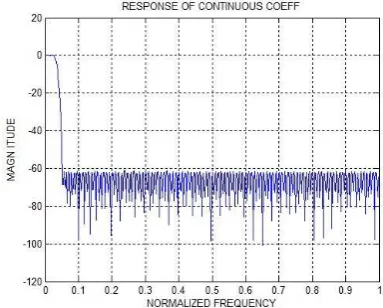
[image:4.595.334.526.160.314.2]The proposed algorithm has been applied for the design of the dis-crete interpolator low pass filter with the specifications given in Section 5. Continuous coefficient filter outputs when designed us-ing farrow are compared with those of sus-ingle stage FIR interpolator and are given in Table 2. The frequency response for farrow based interpolator with infinite precision is given in Figure 4.
Table 2. : Continuous Coefficient Implementation Comparison
Passband Ripple
Stopband
Attenuation Implementation Complexity
Multipliers Adders FIR
Based 0.0837 -60.3181 109 217
Farrow
Based 0.069865 -60.827485 58 128
The modified farrow structure based interpolator is made multiplier-less using CSD representation. Range and resolution of CSD look-up-table (LUT) is selected from 12,14,16 bit, consider-ing hardware complexity and closeness to required specification.
[image:4.595.329.542.394.481.2]From Table 3, with 12-bit maximum precision representation, the stop-band attenuation is about 20% degraded than the specified value. 16-bit representation results in more number of adders. Thus, 14 bit CSD with maximum two SPT terms is selected. A typi-cal look-up-table entry is shown in Table 3. It has four fields for each value; index, CSD form, corresponding decimal equivalent and number of non-zero in CSD representation.
[image:4.595.58.289.553.632.2]Fig. 4: Farrow based Interpolator response with infinite precision
Table 3. : CSD Selection Criteria
CSD Maximum SPT terms
Passband Ripple
Stopband Attenuation
Number of Adders 12 6 0.093070 -47.818635 142 12 2 0.196655 -36.105662 65 14 7 0.077853 -53.359743 198 14 2 0.198311 -36.501081 73 16 8 0.074097 -60.549716 269 16 2 0.198523 -36.546469 81
The degradation in performance is given in Figure 5. The perfor-mances can be revived using optimization techniques. In this pa-per,ABC optimization algorithm is deployed to improve the perfor-mances of the CSD coefficient filter. The different parameters of the algorithm are initialized as given in Table 6. The coefficients of all the filters are CSD rounded and concatenated as a vector to form the initial food source. Only half the number of coefficients are used, since all the filters have linear phase. Convergence of ABC algorithm for this particular application is shown in Figure 6.
Table 4. : Sample CSD look up table entries
Index CSD
Representation
Decimal Equivalent
No. of Nonzero Terms
[image:4.595.332.543.633.673.2]Table 5. : FIR and Farrow Based Interpolator Comparison
Average
SPT Terms
Passband
Ripple
Stopband
Attenuation
Number of
Multipliers Adders
Structural SPT Total
FIR
Continuous
CSD 14 bit
ABC
-7
2
2.54
0.08365
0.084937
0.108684
0.0867213
-60.318144
-54.696398
-37.552719
-56.3425575 109
-217
217
217
217
-340
189
334 217
557
406
551
Farrow
Continuous
CSD 14 bit
ABC
-7
2
3.05
0.069865
0.077853
0.198311
0.0745596
-60.827485
-53.359743
-36.501081
-57.9993861 58
-128
128
128
128
-198
73
179 128
326
201
[image:5.595.86.263.319.353.2]307
Table 6. : Parameters for ABC Algorithm
Number of Employed Bees
Number of Onlooker Bees
Numberof Limit Cycles
50 50 250
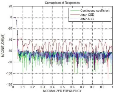
An FIR filter of the same specification is designed and made multiplier-less to compare with the current design. The optimiza-tion funcoptimiza-tion is set such that, emphasis is given for hardware com-plexity in both the cases. The above mentioned farrow structure is implemented as interpolator. This is compared with classical Parks-McClellan (FIRPM) method and is found to have lesser arith-metic complexity as can be observed from Table 6. The FIR based multiplier-less interpolator requires 109 multipliers and 551 adders. The farrow based interpolator has no multipliers and requires only 307 adders. Frequency response of the filter after optimization as compared to continuous coefficient and CSD converted with mini-mum SPT terms is shown in Figure 5.
Fig. 5: Comparison of Frequency Responses
7. CONCLUSION
In this paper, a multiplier-less farrow structure based linear phase low pass interpolation filter is designed and optimized in the dis-crete space using a modified artificial bee colony meta-heuristic algorithm. The performances and implementation complexity are compared with those of a multiplier-less FIR based single stage in-terpolation filter designed for the same specifications. It is observed that there is a 28% reduction in the number of adders. Reduction in the implementation complexity can lead to less power consump-tion, chip area and cost.
Fig. 6: Convergence proof of ABC algorithm
8. REFERENCES
[image:5.595.335.544.425.592.2] [image:5.595.72.264.511.666.2][2] C W Farrow. A continuously variable digital delay element. InCircuits and Systems, 1988., IEEE International Sympo-sium on, pages 2641–2645. IEEE, 1988.
[3] J Vesma and T Saramaki. Optimization and efficient imple-mentation of fir filters with adjustable fractional delay. In Circuits and Systems, 1997. ISCAS’97., Proceedings of 1997 IEEE International Symposium on, volume 4, pages 2256– 2259. IEEE, 1997.
[4] H Johansson and P Lowenborg. On the design of adjustable fractional delay fir filters.Circuits and Systems II: Analog and Digital Signal Processing, IEEE Transactions on, 50(4):164– 169, 2003.
[5] H˚akan Johansson. Farrow-structure-based reconfigurable bandpass linear-phase fir filters for integer sampling rate con-version.Circuits and Systems II: Express Briefs, IEEE Trans-actions on, 58(1):46–50, 2011.
[6] Amir Eghbali and H˚akan Johansson. Reconfigurable two-stage nyquist filters utilizing the farrow structure. InISCAS, pages 3186–3189, 2012.
[7] Amir Eghbali and H˚akan Johansson. A class of reconfigurable and low-complexity two-stage nyquist filters.Signal Process-ing, 96:164–172, 2014.
[8] M Manuel and E Elias. Design of frequency response mask-ing fir filter in the canonic signed digit space usmask-ing modified artificial bee colony algorithm. Engineering Applications of Artificial Intelligence, 26(1):660–668, 2013.
[9] TS Bindiya and E Elias. Design of multiplier-less reconfig-urable non-uniform channel filters using meta-heuristic algo-rithms. International Journal of Computer Applications, 59, 2012.
[10] B Webb. Swarm intelligence: From natural to artificial sys-tems. 2002.
[11] D Karaboga. An idea based on honey bee swarm for nu-merical optimization. Technical report, Technical report-tr06, Erciyes university, engineering faculty, computer engineering department, 2005.