ISSN 2250-3153
Implementation of Bill Deduction in ETC System
based on IoT and RFID Technology
Aung Naing Tun1, Nay Win Zaw2, Hla Myo Tun3
1,2
Department of Electronic Engineering, West Yangon Technological University, Myanmar 3
Department of Electronic Engineering, Yangon Technological University, Myanmar [email protected], [email protected], [email protected]
DOI: 10.29322/IJSRP.8.4.2018.p7640 http://dx.doi.org/10.29322/IJSRP.8.4.2018.p7640
Abstract
The paper presents the bill deduction with cloud of Thingspeak webserver in Electronic Toll Collection (ETC) system for toll tax collection based on IoT and RFID technology. The existing toll collection systems in Myanmar have been applied to manual cash Management observed in past years. Manual toll collection systems are main blockage of high speed commutation scheme. The paper points out the office computerization system using internet of things technology. All data can be processed and transferred by applying Thingspeak website to upload the data over cloud server. Then the message data could be displayed with the scanned RFID cards, bill deduction records and the number of passing cars on Toll plaza on the android mobile phone which was sent by wireless communication environments. This work has been implemented ETC system using RFID reader with passive RFID tags, ESP8266 Node MCU Wi-Fi and Blynk software which has already installed into the android mobile phone. The toll is deducted by administrative user account for every time and it can be passed through a toll plaza. The electronic system can convey transparency in toll tax collection and make anti-corruption and tax evasion issues.
Key Words: Bill Deduction, Internet of Things, Wireless Technology, ETC System, Hardware Implementation, Software Development
1. Introduction
Radio frequency identification (RFID) is one of the wireless communication technologies that can be used to distinguish tagged objects, people or animals. The applications areas for RFID are growing speedily. This
includes supply chain management, access control to building, security systems, animal identification, public transportation, healthcare, open-air events, air-port baggage, and excess parcel logistics and so on. RFID scheme consists of readers and a huge number of tags. A tag has an identification number (ID) and a reader recognizes an object through consecutive communications with the tag fond of it. The reader sends out a signal which supplies power and instructions to a tag. The tag transmits its ID to the reader consults an external database with received ID to recognize the object. In this paper, RFID system has been developed with 125 kHz, FSK modulation scheme. Toll tax collection systems in Myanmar are based on manual cash business. The operator at the toll booth manually collects toll amount according to vehicle type, in form of cash invoices. He hands the receipt for same amount. This may be time consuming. Due to that systems blockage, the proposed method is created in the high speed highways. There are chances of error, time wastage, and longer queues leading to fuel wastage. The IoT-based electronic toll collection system works as a centralized server which stores database of users. It has private android open source paper support of Apache, JobQueue, Facebook Android SDK and Twitter Kit for Android for a standalone function.
2. Related Works
ISSN 2250-3153
that system might not work effectively. The [2] presented overhead camera to detect number plate and used it as the account number of the user. Database is stored in central server. But decline of number plates or duplicate numbers might introduce false positives in the system. The [3] worked on NFC chips for detection of vehicle identity. The NFC chips were designed to effort in the close environs of the reader. If the distance between reader and chip is more than critical limit, that system would not detect to the vehicle. Considering the limitations of many past systems, RFIDs are prominent with many recompense and the tags needs no battery as they can work completely with the power transmitted by RFID reader. Distance of tag from reader is no issue as high power radio waves can easily detect the tag up to sufficient distance for recognition. Unlike Wi-Fi it does not require any authentication consequently faster than system has been proposed in [1]. More to this system, the IoT based toll collection system using Blynk Cloud of account “[email protected]” can be provided a cost effective implementation as components are fairly inexpensive.
3. System Design
This system was implemented with following hardware components:
• ESP8266 Node MCU
• RFID Reader RC 522
• RFID passive tags
Figure.1. Block Diagram of ETC Bill System
4. RFID Reader
A Radio Frequency Identification scheme consists of an antenna or coil, a transceiver and a transponder programmed with original information. RFID tag consists of a microchip associated to an antenna, which
is created to a small coil of wires. Data can be stored in the IC and transmitted through the antenna to a reader. Most RFID tags enclose as a minimum of two elements. One is an integrated circuit for accumulating and processing information, modulating and demodulating a RF signal, and other particular functions.
Figure.2.RFID Card Reader
The next is an antenna for receiving and transmitting the signal. A reader is fundamentally a radio frequency RF transmitter and receiver, managed by a microprocessor. It works on a 5V power supply. Typical power consumption is less than 50mA. The reader, using an attached antenna, captures data from tags, then passes the data to the cloud.
The number controlled in RFID tag is of 11 digits in HEX format. This number is sent via either serial interrupt or Wiegand protocol [4-5].
5. System Working
When the vehicle passes through the toll plaza, the RFID tag can be detected by the RFID receiver positioned overhead. This reader is regularly emitting RF waves at 125 kHz. As soon as the tag comes in field of receiver, the tag number is detected and sent to MCU (Microcontroller Control Unit) via serial port communication. The LCD can be displayed the message from the card detection and the card number.
If sufficient balance is found in corresponding user account then stipulated amount will be deducted. This amount depends upon the sort of vehicle. The motor driver can control to open the gate for 30 seconds and the vehicle can cross the toll booth. In case of insufficient balance in the user account, the user could have to pay toll cash in manually with some penalty. The user can easily recharge the certain account from the toll booth itself. The sort of vehicle from initial registration can be identified. New user can also be registered at the toll booth.
Current system is used as a prepaid mode. This can be changed to postpaid. For the prepaid system online recharge system can be realized. By using the Blynk Community of third party and ESP8266 Node MCU
ESP
8266
Node
MCU
Wi-Fi RFID
Reader RFID
Tag
Motor ( Gate )
Motor Driver
Cloud
Android Mobile
ISSN 2250-3153
Wi-Fi to get the most stable system of RFID through Thingspeak web and cloud server. These bill deduction and passing number of tolled cars can be accomplished the Blynk interface via Android phone.
START
Read the ID number
Register?
Sufficient balance?
Deduce the balance & sent deposit to microcontroller
Traffic gate open
END
Update the balance New registration
YES
YES NO NO
IR sensor sense the vehicle and gate close Display
deposits on LCD
Microcontroller
Figure.3. Flowchart of ETC Bill System
Many types of RFID subsist, but at the higher level, there are two classes into the RFID devices: active and passive. Active tags necessitate a power source they’re either connected to a powered infrastructure or use energy stored in an integrated battery. In other case, a tag’s lifetime is limited by the stored energy, balanced against the number of read operations the device must undergo. On the other hand, batteries make the cost, size, and life-time of active tags impractical for the retail trade. Passive RFID is relevant because the tags don’t require batteries or preservation. The tags also have an indefinite operational life and are small enough to fit into a practical adhesive label. A passive tag consists of three parts: an antenna, a semiconductor chip attached to the antenna, and some form of encapsulation.
The tag reader is conscientious for powering and communicating with a tag. The tag antenna captures energy and transfers the tag’s ID. The encapsulation maintains the tag’s integrity and protects the antenna
and chip from environmental circumstances or reagents. The encapsulation could be a small glass vial or a laminar plastic substrate with adhesive on one side to enable easy attachment to goods. Two basically different RFID devise approaches exit for transferring power from the reader to the tag: magnetic induction and electromagnetic (EM) wave capture.
These two designs obtain benefit of the EM properties associated with an RF antenna-the near field and the far field. Both can relocate sufficient power to a remote tag to keep going its operation characteristically between 10 W and 1mW, depending on the tag type. Through various modulation methods, near-and far-field-based signals can furthermore transmit and receive data [4-5].
6. System Components
There are three main components to inclusive the full system for implementation.
6.1. ESP8266 Wi-Fi Module:
The ESP8266 is a low-cost Wi-Fi chip with full TCP/IP stack and has MCU potential. Expressive Systems’ Smart Connectivity platform (ESCP) is a set of high recital, high incorporation wireless SOCs, intended for space and power constrained mobile platform designers. It offers unsurpassed ability to embed Wi-Fi capabilities within other systems, or to function as a separate relevance, with the lowest cost, and minimal space prerequisite.
6.2. Node MCU:
The Node MCU is firmware is a cohort paper to the popular Node MCU dev kits, ready-made open source development boards with ESP8266-12E chips. The Node MCU is an open-source firmware and expansion kit that helps the prototype IoT product within a script lines.
6.3. Thingspeak:
ISSN 2250-3153
Figure.4. Flow Chart of Software Configuration
. Figure.5. Mobile hotspot
Figure.6.Blynk Software configuration
Figure.7. RFID and ESP8266 based ETC Bill System
Figure.8. Balance Monitor of ETC Bill System
Figure.9. Total Passing Cars in Toll Plaza
Start
Mobile hotspot to
Turn on
Blynk on
Type
Read RFID cards
Password:
ant.rfid
ISSN 2250-3153
[image:5.539.71.233.200.326.2]Figure.10. Access Denied Car of ETC Bill System
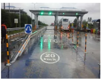
Figure 11. ETC Lane of No.3 Joint at Yangon-Mandalay High Way
Figure 5 to 11 show the experimental results with the help of software and hardware implementation. The implementations were successfully completed based on the proposed method. The accuracy of the proposed system could easily measured by using the modified techniques for ETC system. The effectiveness of the proposed method is high performance and greater accuracy based on the analysis on proposed system.
8. Conclusion
This RFID based electronic toll collection gate has been implemented in this paper. Every RFID card has some amount to be paid in toll gate. When the car gets to the toll gate, the users need to detect their RFID card to RFID reader. Then the system deducts specific amount along with their car sort. Each RFID card encloses user identification, License number and some other information. This paper has been applied ESP8266 Node MCU and MFRC522 RFID card reader to system with Serial Peripheral Interface. The Blynk LCD of advanced mode is utilized in this paper. RFID based toll bill deduction system is more secure and fast responded as compared to the system like biometric. By using Arduino it is effortless to contact and works very
speedily while burning the code and changes the function. Data analysis over the cloud is also uncomplicated using ThingSpeak website.
Acknowledgement
The author would like to thank my supervisor, head and all of my teachers from Department of Electronic Engineering, West Yangon Technological University who gave suggestions, consistent guidance, encouragement, motivation and support throughout the research period. Also, the author would like to thank the kind and patient suggestions of Mr. Yan Myo Aung of YTU, Yangon in Myanmar. Without their help it was tough job for me to accomplish this task.
References
[1] Vijay Jadhav “Office Automation & Attendance System using IoT” IRJET: 04 Issue: 07 | July 2017
[2] Shital Ladkat “M-toll using Wi-Fi Technology” RJET: 03 Issue: 04 | April 2016
[3] Veeravenkatesh “Smart Traffic Control System for Emergency Vehicle Clearance” IJIRCCE Vol. 3, Issue 8, August 2015
[4] S B Shinde “Toll automation system using NFC” JETIR January 2016, Volume 3, Issue 1