Parallel Deformation of the Metals
Chetan Nikhare
Mechanical Engineering Department, The Pennsylvania State University, Erie, USA Email: [email protected]
Received January 30, 2013; revised March 3, 2013; accepted March 15, 2013
Copyright © 2013 Chetan Nikhare. This is an open access article distributed under the Creative Commons Attribution License, which permits unrestricted use, distribution, and reproduction in any medium, provided the original work is properly cited.
ABSTRACT
The metal goes into the plastic deformation after the application of external load. Most of the metal forming industries work on this principle of plastic deformation. Thus the understanding of plastic deformation in the metal forming indus- try is important. The research on the single material plastic deformation has been carried out from many centuries be- fore the era of Tresca. In this study the two metals 0.05% C steel annealed (soft metal) and 0.6% C steel quenched and tempered (hard metal) were deformed plastically in the parallel combination in the composite form. This study has been carried out with simple mathematical theory and simulated numerical model. The comparison shows the exact match between the mathematical and numerical results. It is also observed that the individual metal thickness affects the de- formation flow curve.
Keywords: Plasticity; Bi-Metal; Metal Forming; Mathematical Model; Numerical Model
1. Introduction
Nature has provided, is providing and will provide many materials to use for the better future for all living society on this earth such as soils, rocks, organic and inorganic materials, metals etc. One of the best material which na-ture provided and science proved is metal which have lot of capability in many manners. One of the achievements in the metals is that they can mould in any shape through stamping, forging, casting etc. Many researchers are still working on the metals to get the best composition for the best usage. Keep on changing the composition of metals, alter the mechanical and metallurgical properties and proposed for the particular use. Another way is me-chanically combining of different metal together to alter the mechanical and metallurgical properties. This goes in the composite way. This will provide the new direction of having the advanced materials for use. This will give the new scope to enhance the existing materials through composite direction and can have the best properties mechanically.
Marvin Chester Stone invented the modern drinking straw which was patented on 3 December 1888 [1]. He was the employee at a paper cigarette holder factory in Washington DC. He used the fine piece of paper from the cigarette holder factory and rolled it around a pencil then coated it in wax to prevent it becoming waterlogged. In 1936 two-year-old Julia Friedman tried to sip a drink
at soda fountain corner through the straw which was long enough from her mouth reach. She tried to bend the straw and it kinked and shut the passage of liquid. This situation observed by her father, Joseph Friedman, went home and invented the flexible straw [2]. The concept was to make the tube with stiffer and softer section alternately to make it smooth bend. Similarly if any tube material made in section of hard and soft sections, it will bend nicely.
Composite material signifies that two or more materi-als are combined on a macroscopic scale to form a useful third material. This has the opportunity to examine the different material by naked eye. More usage of fibre- reinforced, resin-matrix composite materials that have high strength-to-weight and stiffness-to-weight ratios have become important in weight-sensitive applications such as aircraft and space vehicles [3].
shell, the toucan and hornbill beaks, and the sheep crab exoskeleton. All examples were in multi-layer composite structures having hard and soft materials.
In the same way, different materials were combined on a microscopic scale, such as in alloying of metal, but resulting materials is, for all practical purposes, macro- scopically homogeneous, i.e., components cannot be dis- tinguished by the naked eye and essentially act together [3]. The another process is carburizing process which produces the surface of the component a layer of car- bon-rich material that after quenching, by whichever technique, should provide a surface that is hard [5]. Also before quenching and hardening process, the non-uni- form thickness of clay was used to alter the microstruc- ture at different section [6]. Both processes created the material in composite structure at micro and meso-scales. Cold working by either peening or rolling can modify the surface microstructures and have significant bearing on the life of the component, as too can surface grinding [5].
The metal capability was analyzed by determining the true stress-strain curve and was frequently called a flow curve because it gave the stress required to cause the metal to flow plastically to any given strain. The most common mathematical equation was a power expression to represent the stress-strain curve [7]. In this paper the two steels are deformed in parallel and the mathematical equation is proposed for the third metal. Further the comparison of mathematical equation was proved through finite element method. It is observed that the mathematical equation has very good agreement with the simulation results.
2. Material
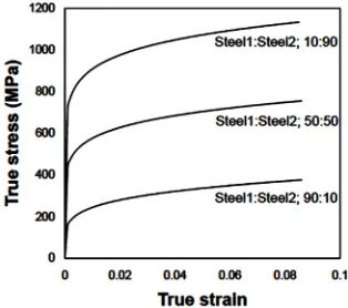
The materials considered for investigation in this study were 0.05% C steel annealed and 0.6% C steel quen- ched & tempered. The former steel was named as Steel1 and another was Steel2 in this study to keep the terms easy. The true stress-strain generated from the power law with the help of n (strain hardening exponent) and K (strength coefficient) is shown in Figure 1. The n and K for the Steel1 was 0.26 and 530.89 MPa and for Steel2 was 0.1 and 1572 MPa [8].
3. Methodology
In this paper the bi-metallic layer rectangular plate was used to perform the deformation. Each layer of the rec- tangular plate was assigned with different material one with soft steel (Steel1) and other with hard steel (Steel2). The simple mathematical solution was proposed to de- termine the true stress-strain curve for this bi-metallic rectangular plate during deformation. Further the nu- merical simulation was performed on this rectangular plate. The numerical observation was then compared
with simple mathematical determination for the flow curve during deformation. In addition the thickness sen- sitivity was analysed.
3.1. Mathematical Solution
The rectangular plate with bi-metallic layer is shown in Figure 2. The rectangular plate was divided horizontally in two parts with thickness t1 and t2. The left side surface was fixed while the displacement was applied on the right face. Consider the deformation is in the plane strain.
Suppose the deformation of material with thickness t1, the flow curve according to the power law is:
1
1 1
n
K
(1)
Similarly consider for material with thickness t2, the flow curve according to the power law is:
2
2 2
n
K
(2)
Thus the flow curve for the parallel bi-metallic layer material would be:
3
3 3
n
K
(3)
It can also be written in terms of 1 and 2, there-fore,
A1A2
3 A11A22A1 and A2 are the cross-sectional area normal to the applied displacement for each material t1 and t2.
[image:2.595.312.532.450.633.2]Thus,
[image:2.595.313.536.662.719.2]Figure 1. True stress-strain curve for Steel1 and Steel2.
1 2
3 1
1 2 1 2
A A
A A A A 2
(4)
Similarly, it is assumed that
1 2
3 1
1 2 1 2
A A
2
K K
A A A A
K (5)
From Equations (4) and (5), the Equation (3) will be,
3
1 2
1 2
1 2 1 2
1 2
1 2
1 2 1 2
n
A A
A A A A
A A
K K
A A A A
After solving for n3;
1 2
1 1 2 2 3
1 1 2 2
1 ln ln
n n
A K A K
n
A K A K
(6) Thus the flow curve of the material 3 can be determine by the following equation
1 2
1 1 2 2 1 1 2 2 1
ln ln 1 1 2 2 3
1 2
n n
A K A K A K A K
A K A K
A A (7)
3.2. Numerical Model
The rectangular plate with bi-metallic layer (Figure 3(a)) was considered for the numerical simulation. The defor- mation of rectangular plate was performed by using the commercial software package ABAQUS/Explicit 6.8-1. The rectangular plate was considered as the deformable body. The thickness of the rectangular plate was taken as 2 mm. The plate was divided horizontally into two parts with the individual thickness of 1 mm. The length of the rectangular plate considered was 50 mm. The left end of the plate was fixed while the displacement of 10 mm was applied to the right side of the plate on the reference point. To apply the displacement on the deformable body the reference point required in ABAQUS. This reference point refers the surface where the displacement or load was applied. In this case the reference point refers the right side surface of the rectangular plate. One plate was assign with the material properties of Steel1 and Steel2 was assign to another plate. Thus both materials were
[image:3.595.64.288.79.304.2](a) (b)
Figure 3. Composite Steel1 and Steel2 with 50:50 combina- tion.
parallel to each other in the deformation direction. C3D8R 8-node linear brick elements were used through the material thickness (Figure 3(b)).
3.3. Thickness Sensitivity
In the above section both layers were considered with same thickness. To understand the deformation behavior of the bi-metallic layer is sensible to the thickness of the individual layer, the two combinations were studied. The first combination was 90% Steel1 and 10% Steel2. Thus the thickness of the Steel1 layer was 1.8 mm and Steel2 was 0.2 mm. The second combination was vice-versa of the first.
4. Results and Discussion
4.1. Mathematical Model
The true stress-strain curves calculated from mathemati- cal proposed equation for all three combinations for Steel1 and Steel2 are shown in Figure 4. The mathe- matical equation shows that n value for the composite material is dependent on strain. The n and K values for all three combinations are determined at 5% strain are shown in Table 1.
4.2. Numerical Model
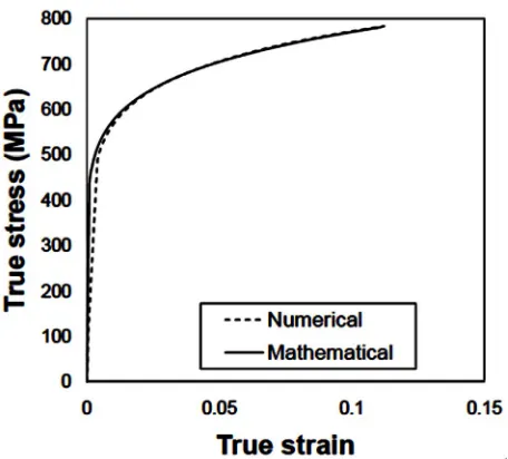
Figure 5 shows the deformed rectangular plate for 50:50; Steel1 and Steel2 combination. The neck region supposes to happen at the middle of the plate length. The com- parison shows (Figure 6) very good agreement of true stress-strain obtained from the numerical model with mathematical equation.
[image:3.595.345.502.569.708.2]The deformed rectangular plate for 90:10 combination of Steel1 and Steel2 is shown in Figure 7. The uniform deformation is observed in this case. The true stress- strain curve obtained from the numerical simulation is compared with mathematically obtained flow curve in Figure 8. The very good co-relation obtained between both curves.
[image:3.595.59.287.625.708.2]Figure 5. Deformed plate of 50:50 combination of Steel1 and Steel2.
[image:4.595.59.287.223.429.2]Figure 6. True stress-strain curve for 50:50 combination of Steel1 and Steel2.
Figure 7. Deformed plate of 90:10 combination of Steel1 and Steel2.
Table 1. n and K values for all three combinations of Steel1 and Steel2.
n K (MPa)
Steel1:Stee2; 50:50 0.133 1051
Steel1:Steel2; 90:10 0.212 635
Steel1:Steel2; 10:90 0.104 1467
[image:4.595.311.539.387.496.2]The third combination of 10:90 for Steel1 and Steel2 composite deformation is shown in Figure 9. The neck observed near to the fixed side of the plate. The com- parison of mathematical determined true stress-strain curve has very good validation with the numerical simu-lation result (Figure 10).
Figure 8. True stress-strain curve for 90:10 combination of Steel1 and Steel2.
Figure 9. Deformed plate of 10:90 combination of Steel1 and Steel2.
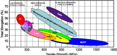
[image:4.595.58.288.468.578.2] [image:4.595.314.530.535.711.2] [image:4.595.57.287.642.735.2]This gap can be filled with the help of mentioned con- cept in this paper by mechanical and metallurgical proc- essing the available materials to produce the novel mate- rials. These materials can fill the gap and can produce the new area for material development. The new material area can be called as Mechanical and Metallurgical Composite Steels.
[image:5.595.59.285.85.191.2]REFERENCES
Figure 11. Ductility-strength relationships for steels.
[1] M. C. Stone, “Artificial Straw,” US 375962, 1888.
[2] J. B. Friedman, “Flexible Drinking Straw,” US 2550797, 1951.
5. Conclusions
The concept to deform the mechanically joined two ma- terials is proposed in this study. The deformation of the composite of two steels is analyzed through mathemati- cal and numerical solutions. The determination of the basic mechanical properties for the composite materials through the mathematical solution is proposed. It is found that the n values for the composite material is de- pendent on strain. The numerical model for the compos- ite material is developed and compared with the mathe- matical solutions. The comparison shows very good agreement for all analyzed condition. This co-relation confirmed the proposed mathematical solution. This study gives the base line for more development of mate- rials in the gap mentioned in the banana diagram for steel (Figure 11).
[3] R. Jones, “Mechanics of Composite Materials,” CRC, 1999.
[4] M. A. Meyers, A. Y. M. Lin, Y. Seki, P. Y. Chen, B. K. Kad and A. Bodde, “Structural biological composites: An overview,” Journal of the Minerals, Metals and Materials Society, Vol. 58, No. 7, 2006, pp. 35-41.
doi:10.1007/s11837-006-0138-1
[5] G. Parrish, “Carburizing: Microstructure and Properties,” ASM International, 1999.
[6] Y. Inoue, “Tatara and the Japanese Sword: The Science and Technology,” Acta Mechanica, Vol. 214, No. 1-2, 2010, pp. 17-30. doi:10.1007/s00707-010-0308-7
[7] G. E. Dieter, “Mechanical Metallurgy,” McGraw-Hill, New York, 1986.