© 2017, IRJET | Impact Factor value: 5.181 | ISO 9001:2008 Certified Journal | Page 37
Design and Analysis of a Multi Fingered Gripper for Grasping
Irregular Objects
A.Sathishkumar
1, R.Chandiran
2, D.Venkatesa Prabu
3, M.Sakthivel
41,2,3,4
Assistant Professor, Department Of Mechatronics Engineering, Mahendra College of Engineering, Salem,
Tamilnadu, India
---***---Abstract -
This project deals with design anddevelopment of an advanced multi-fingered gripper designed by using Pro- E and ANSYS. In this research work are motivated by the requirement for grasping of the objects of arbitrary shape and size. The key issues consider here are: the gripper should be able to grasp the object of any shape, size, and weight (with a maximum limit); stability of the object held during the manipulations; should not dependent on the frictional forces between gripper and object; synchronization in fingers motion; and employment of the minimum number of the actuators to manipulate the grippers.
Kinematic and dynamic analyses of the gripper are made to support this novel design. The gripper was successfully designed, Analyzed hence can find many applications, e.g., as a robot end effectors, prosthetic hands etc. The robotics, end effectors are a device at the end of a robotic arm, designed to the interact with the environment. Gripper was ending effectors or tool to grasp any physical thing that may be a human hand or any instruments. This type of gripper designed is an impactive type which uses jaws or claws to the physically grasp by direct impact upon the object. A pneumatic pressure was used to actuate the fingers of the gripper. In this project, a simple mechanism is developed for grasping irregular object shapes by using a four-fingered robotic gripper. To the achieve this goal we intend to the incorporate a simple linkage actuation mechanism. The gripper can perform the basic function of picking, holding and grasping of the irregularly shaped objects. The grippers are simple in construction, minimum complexity, and easy manufacturability. The focuses of this project are to achieve four-finger grasp of the irregularly shaped objects.
Key Words
: Design and Development, Robotics, Multifingered Gripper.
1. INTRODUCTION
1.1 Robot Vs Robotics
A robot was a mechanical or virtual artificial agent, usually an electro-mechanical machine that is guided by a computer program or electronic circuitry. The Robot can be autonomous, semi-autonomous or remotely controlled and the range from humanoids such as ASIMO and TOPIO to the Nanorobots, 'swarm' robots and industrial robots. By the mimicking a lifelike appearance or automating movements, a robot may be conveying a sense of the intelligence or thought of its own. The branch of technology that deals with robots was called robotics.
It is the branch of technology with deals the design, construction, operation and the application of robots the computer systems for their control, sensory feedback, and information processing. These technologies deal with the automated machines that can take the place of humans, in hazardous or manufacturing processes, or simply just resemble humans. Many of the today's robots are inspired by nature contributing to the field of robotics. The word robotics is derived from the word robot, which was introduced to the public by Czech writer Karel Čapek in his play Rossum's Universal Robots, which premiered in 1921. The word is robot comes from the Slavic word robota, which are used to refer forced labor. Actuators were like the "muscles" of a robot, the parts which convert stored energy into the movement. By far the most popular actuators were electric motors that spin a wheel or gear, and linear actuators that control industrial robots in factories. But there were some recent advances in alternative types of the actuators, powered by electricity, chemicals, or compressed air.
© 2017, IRJET | Impact Factor value: 5.181 | ISO 9001:2008 Certified Journal | Page 38
few has one very general purpose manipulator, for anexample of the humanoid hand.
1.2 Grippers
One of the most common effectors is the gripper. It is the simplest manifestation, it is consists of just two fingers which can open and close to the pickup and let go of a range of a small object. Fingers can, for example, be made of a chain of a metal of wire run through it. The Hands that resemble and work more like a human hand include the Shadow Hand, the Robonaut hand. The Hands that were of a mid-level complexity include the Delft hand. Mechanical grippers can come in the various types of including friction and encompassing jaws. The friction jaws use all force of the gripper to hold the object in place using friction. The Encompassing jaws cradle the object in place, using less friction. Vacuum gripper is very simple astrictive devices but can hold very large loads provided the pretension surfaces are smooth enough to ensure suction.
1.3 Choosing Number of Fingers
A lot of discussions are going to finalize the number of fingers in a gripper. The Harmon suggests that only three fingers were required to reproduce the most frequent and the common human grasps. Brown and Hazelton et al. found that the middle, ring, little finger provide the strength needed for a firm grip. Although not a heavily loaded themselves, the thumb and index finger serve as retainers to make the grip undulate precisely. Chua suggested that in the fingertip pretensions, stability were usually achieved with the index finger and thumb. Literature suggests that the thumb, index and the middle finger will be providing sufficient dexterity during manipulation. The thumb and index finger will be ensuring a precise and stable grip, while the middle finger will be providing the necessary strength. The most studies of gripper design had proceeded under assumption that the frictional force will large enough to keep the object from sliding in the fingers, however, in practice; it are very difficult to ensure that the frictional forces between the fingertips and the object were sufficiently high to hold the object. The most of the grippers used now days were simply two-fingered gripper. However, two fingered configuration wouldn’t ensure a safe grasp as the sideway slip can easily occur if any irregularities were present on the object’s surface or the object are held in the way that the center of gravity doesn’t become collinear with the forces of applied by the gripper’s fingers. Other grippers,
which have more than two fingers, use the motors on each joint of the finger, which reduces the load holding capacity of the gripper due to self-weight of the motors.
1.4
Human Hand
The human hands have always been a fascination for scientists. The studies of human hands have long been an area of interest for hand surgery, for the designing prosthetic devices and for quantifying the stretch of disability in individuals with congenital defects or wounded. The ideal end-effectors for such an artificial arm would be able to use the tools and objects that a person uses when working in the same environment. The human hands are a very complex grasping tool that can be handle objects of different sizes and shapes. The many research activities has been carried out to develop artificial robot hands with a capability similar to the human hand, which remains as a highly complex structure that in many ways defy understanding.
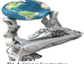
1.5 Gripper Construction
[image:2.595.359.527.445.573.2]The grippers are simple in construction, minimum complexity and easy to manufacturability.
Fig -1: Gripper Construction
2. OBJECTIVE
© 2017, IRJET | Impact Factor value: 5.181 | ISO 9001:2008 Certified Journal | Page 39
The gripper was simple in construction, minimumcomplexity and easy to manufacturability. The human hand’s design forms the basis of this project of developing a robotic gripper and the source of inspiration for the lines of which we intend to achieve the sufficient level of dexterity in the domain of grasping, manipulation if coupled with wrist and arm. The focuses of this project have been to achieve four-finger grasp of irregularly shaped objects.
2.1 About multi Fingered Gripper
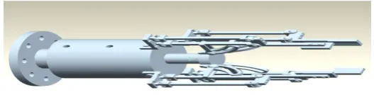
[image:3.595.299.560.219.399.2]It is a device that grasps, retains and eventually releases a workpiece.
Fig -2: Graphical representation
It can be held, tighten, handle and release an object just like the human hand. This type of gripper designed is an impactive type which uses jaws or claws to the physically grasp by directly impact upon the object. A multi-fingered robotic gripper has the potentiality to achieve dexterous manipulation. It has the functions of:
Stably grasping an object of any shape adaptably Manipulating the grasped object from the initial
pose to the desired pose.
2.2 Classification of gripper on the basis of
number of jaws
Fig -3: Basic Model of Four Fingered Gripper
Grippers can also be classified on the basis of the number of jaws that can be used to hold the workpiece.
The two-jaw grippers are the most popular style. The gripper-either angular or parallel provides two mounting locations for the fingers to contact the part. The jaw moving a synchronous motion, opening and closing towards the central axis of the gripper body.
The three-jaw grippers are more specialized style. These include parallel, concentric grippers and provide three mounting locations for the fingers that can contact the part. The jaw moves in a synchronous motion, opening and closing towards the central axis of the gripper body. The three jaws provide more than contact and accurate centering with the part than two-jaw grippers do.
[image:3.595.36.280.259.339.2]
Fig -4: Methodology process
2.2.1 Design consideration of Multi finger Robot
Among all the problems encountered in designing robots, the most crucial one concerns with the end- effectors. Basic features for a gripper depend on strongly on the grasping mechanism. Thus, factors can be considered before choosing a grasping mechanism as following:
The characteristics of a gripper, which include a maximum payload, dimensions, orientations, a number of the composed links.
This characteristic of the objects, which include weight, body rigidity, nature of the material, geometry, dimensions, condition, position, orientation, contact surfaces and forces acting on the object and environmental conditions.
The gripper technology, for the construction of components with proper manufacturing and materials.
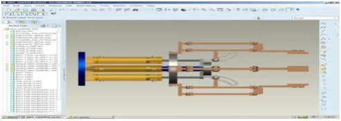
[image:3.595.35.299.558.625.2]© 2017, IRJET | Impact Factor value: 5.181 | ISO 9001:2008 Certified Journal | Page 40
Fig -5: pro-E model The Cost of design, production, application to the robot operation and maintenance. In fact, those characteristics were fundamental from a practical viewpoint for the grasping purpose; since they are many describe the range of exerting the force on the object by the fingers, the size of the range in objects which may be grasped and a particular manipulation types. Thus, a dimensional gripper. Design of the gripper mechanisms may have great
influence on the maximum dimensions of the grasped object by the gripper on the grasping force, since this mechanism size may affect the grasp configuration and transmission characteristics. These peculiarities can be considered well known when it was taken into account the great different types of mechanisms which have been used.
2.2.2 Factors Focusing
Impactive Ingressive Astrictive Contigutive
Force and torque considerations
2.2.3 Conceptual Design of the Four Fingered
Gripper
It should be able to grasp the irregular objects of different types of shape and size.
It should be able to take different loads. It should be stability during the manipulations. It should be independent of the friction coefficient
between an object and the gripper. Synchronization is the finger of motion. Employment of minimum number of actuators. It shouldn’t slip, so there should be a provision of
the interlocking.
It should simulate the human hand.
It should be precisely controlled (through a computer or manually).
It should be of lightweight.
It should easily fabricate with the readily available resources.
It should be of low cost.
2.2.4 Generative 3Dimentional Modeling
It is well known that minimum three points are required to hold any object. In my project work, a four-fingered gripper each with two limbs have been designed to be held irregular objects as this can be used for both force and form to closure purpose. In comparison to gripper with single limb where it may fail if the friction force is not sufficient, here the presence of the second limb will augment the friction force and will help in firmly gripping the object. The gripper consists of a base, four fingers with two limbs each two motors are placed centrally. In order to control the two limbs of each finger, two independent actuators are required. Hence, in this case with three fingers, one may require six actuators.
Fig -6: Pro-E Model Of Four Fingered Gripper Inner Construction
2.2.5 Analytical calculation
1. Consider power calculations:
The compression air motor are used to an electric D.C. motor which are of 12 Volt and producing direct current of 35 A.
Power transmitted is P = V.I
= 35 x 12
Power = 420 W
© 2017, IRJET | Impact Factor value: 5.181 | ISO 9001:2008 Certified Journal | Page 41
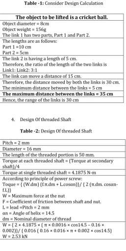
Table -1: Consider Design CalculationThe object to be lifted is a cricket ball.
Object diameter = 8cmObject weight = 156g
The link 1 has two parts, Part 1 and Part 2. The lengths are as follows:
Part 1 =10 cm Part 2 = 5cm
The link 2 is having a length of 5 cm.
Therefore, the ratio of the length of the two links is Link1: Link2: 3:1
The link can move a distance of 15 cm.
Therefore, the distance moved by both the links is 30 cm. The minimum distance between the links = 5 cm
The maximum distance between the links = 35 cm Hence, the range of the links is 30 cm
[image:5.595.31.289.99.610.2]4. Design Of threaded Shaft
Table -2: Design Of threaded Shaft
Pitch = 2 mm Diameter = 16 mm
The length of the threaded portion is 50 mm.
Torque at each threaded shaft = (Torque at secondary shaft)/4
Torque at single threaded shaft = 4.1875 N-m According to principle of power screw:
Toque = { (W.dm) (f.π.dm + L.cosαn)}/ { 2 (π.dm. cosαn- f.L)}
W = Maximum force at the nut
F = Coefficient of friction between shaft and nut. L = lead =Pitch = 2 mm
αn = Angle of helix = 14.5
dm = Nominal diameter of thread
W = { 2 × 4.1875 × ( π × 0.0016 × cos14.5 – 0.16 × 0.002)}/ { 0.016 ( 0.16 × 0.016 × π + 0.002 × cos14.5} W = 2.53 kN
5. Position of FINGER in space in angle of inclinations Ɵ1=30°=angle of link1,
Ɵ2=75°=angle of link2, then
Position (Ɵ1, Ɵ2) = Pj (30°, 75°)
Position of FINGER in space in x, y co-ordinates
Length of FINGER in x direction,
Length of FINGER in y direction,
L1 =0.01m = Length of link1,
L2 =0.01m = Length of link2
r1 = Position vector of link 1,
r2 = Position vector of link 2,
r1 = (L1 Cos Ɵ1, L1 Sin Ɵ1) ,
r1 = (0.01Cos 30°, 0.01Sin75°)
r1 = (0.008m, 0.009m)
r2 = (L1 Cos (Ɵ1+ Ɵ2), L2 Sin (Ɵ1+ Ɵ2))
r2 = (0.01 Cos (30°+75°), 0.01 Sin (30°+75°)),
r2 = (-0.0025m, 0.0096m)
x = L1Cos 30°+ L2Cos (30°+75°),
x =0.08+-0.002
= 0.0774m
y = L1Sin30°+ L2 Sin (30°+75°)
y =0.005+0.00965
=0.014m
Position of FINGER in space in x, y co-ordinates
=Pw (0.0774m, 0.014m)
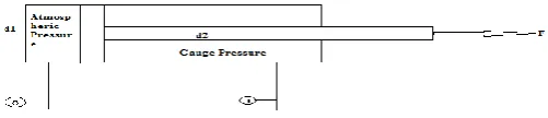
6. Design Of Double Acting Pneumatic Cylinder
© 2017, IRJET | Impact Factor value: 5.181 | ISO 9001:2008 Certified Journal | Page 42
more than desirable where cleanliness are a [image:6.595.41.292.220.274.2]requirement. The double-acting cylinders which use the force of air to move in both extend and retract strokes. They have two ports to the allow air in, one for return stroke and one for forwarding stroke. The stroke lengths for this design are not limited; however, the piston rods are more vulnerable to buckling and bending.
Fig -7: Double Acting Cylinder
The force exerted by a double acting pneumatic cylinder on the outstroke can be expressed as the force exerted on in stroke can be expressed as
F = p π (d12 - d22) / 4
Where
d1 = Full bore piston diameter (m)
d2 = Piston rod diameter (m)
3. RESULTS AND DISCUSSION
3.1 Kinematic Analysis for Fingers
In this section, the kinematic analyses of the gripper were performed. The analyses were performed as two separate parts. The first one was the kinematic analysis for the fingers and the second one was the kinematic analysis for a thumb. The displacement vectors were derived inside this section. Also, the velocity vectors for fingers and thumb were derived and given in Appendix G in the order to be available for dynamic analyses. At beginning of the kinematic analysis, coordinate axes and origin of the system are determined. Since the fingers were fixed at the gripper is palm, center of the joint 1 are defined as coordinate axis origin and axis are placed as shown in Figure
Table -3: Force and Torque Values for Actuator Forces and Torques
Torque at 6 bar [Nm] 2
Maximum swiveling frequency [Hz] 3 Maximum permissible radial load
[N] 75
Maximum permissible axial load [N] 30
3.2 Force analysis
In this section, the force analyses of the gripper were performed. As the structure of fingers and thumb is different, the calculations are carried out in the two sections like in kinematic analysis so; gripping force is exerted by the gripper are related to the pressure is applied to the actuators of the system. So, the only tip of point force is derived inside the section. During the analysis, gravitational forces and frictional forces were neglected as they are small when compared to the gripping forces.
Table -4: Properties of Aluminum Alloy
Material Density (r, Mg/m3)
Young’ s Modul
us (E, GPa)
Shear Modulus
(G, GPa)
Poission’ s ratio
(n)
Aluminum alloy
(7075-T6) 2.7 70 28 0.34
Yield Stress (s Y, MPa)
UTS (s f, MPa)
Breakin g Strain
(e f, %)
Fracture Toughnes s (K c, MN
m-/2)
Thermal Expansio n (a,
10-6/C)
500 570 12 28 33
3.3 Stress analysis of single arm by using
stainless steel
Three fingers of the gripper are similar in joint numbers and link dimensions.
Table -5: Stress Analysis of Single Arm by Using Stainless Steel
Material Density (r, Mg/m3)
Young’s Modulu
s (E, GPa)
Shear Modulus
(G, GPa)
Poissio n’s ratio
(n) Steel,
stainless austenitic
304
7.8 210 76 0.28
Yield Stress (s Y, MPa)
UTS (s f, MPa)
Breaking Strain (e f, %)
Fracture Toughnes s (K c, MN
m-/2)
Thermal Expansi
on (a, 10-6/C)
© 2017, IRJET | Impact Factor value: 5.181 | ISO 9001:2008 Certified Journal | Page 43
Fig -8: Stress Analysis of Single Arm by Using StainlessSteel
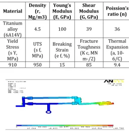
3.4Stress Analysis of Single Arm by Using
Titanium Alloy
Table -6: Stress Analysis of Single Arm by Using Titanium Alloy
Material Density (r, Mg/m3)
Young’s Modulus (E, GPa)
Shear Modulus
(G, GPa)
Poission’s ratio (n) Titanium
alloy
(6A14V) 4.5 100 39 36
Yield Stress
(s Y, MPa)
UTS (s f, MPa)
Breaking Strain (e f, %)
Fracture Toughness
(K c, MN m-/2)
Thermal Expansion
(a, 10-6/C)
[image:7.595.31.289.357.618.2]910 950 15 85 9.4
Fig -9: Stress Analysis of Single Arm by Using Titanium Alloy
The gripping force analysis of the fingers and force analysis of the thumb is given in separate subsections. The developed grippers are pneumatically controlled.
4. CONCLUSION
New dexterous robotic grippers have been designed successfully. Through the use of four fingers with two limbs in each finger, the gripper was able to
grasp objects of the various shapes, sizes, and weights. The use of two remotely located actuator reduces the inertia of the manipulator size, complexity and cost of the gripper while increasing the holding capacity. In this gripper can be used in the hostile environment such as nuclear power plant, chemical industries, laboratories, hospitals etc. Even the idea can be used for a humanoid robot.
REFERENCES
[1] Coe, S. and Waldron, K.J., “Mechanical Design of the DIGITS System,” 1st National Applied Mechanisms and Robotics Conference, paper no. 89AMR- 8C-5, Nov. 1989.
[2] Jacobsen, S. C., Iverson, E. K., Knutti, D. F., Johnson, R. T., Biggers K. B., “Design of the Utah/M.I.T. Dextrous Hand”, IEEE Transactions of Robotics and Automation”, April 1986.
[3] Mason. M.P, Salisbury, J.K., “Robot Hands and the Mechanics of Manipulation”. MIT Press, Cambridge, Massachusetts, 1985.
[4] Suhaib Md., Mukherjee S., Khan R.A., “Dexterous Rotation of Cube By Multifingered robotic hand”, Proc. National Conference on TIME-2003,KITS Warangal, India, Aug 2003.
[5] Juvinall Robert C.,Marshek Kurt M.,”Fundamentals of machine component design”,Wiley student edition,2007.
[6] Monkman Gareth J., Hesse Stefan,Steinmann Ralf, Schunk Henrik,”Robot grippers”, Wiley-VCH Verlag GmbH and Co. KGaA,2007.
[7] S.Ramasamy and M.R.Arshad, "Robotic Hand Simulation with Kinematics and Dynamic Analysis", Intelligent Systems and Technologies for the New Millenium - TENCON 2000 Proceedings (IEEE), III- 178, Kuala Lumpur.
[8] Bicchi, A. (2000) hands for Dexterous Manipulation and Robust Grasping: A Difficult Road toward Simplicity. IEEE Transactions on Robotics and Automation 16 (6) 652-662.Piscataway, IEEE press.
[9] Toshio Morita, Hiroyasu Iwata and Shigeki Sugano(2000) “Human Symbiotic Robot Design based on Division and Unification of Functional Requirements”, Proceedings of the 2000 IEEE International Conference on Robotics and Automation, pp.2229-2234.