© 2017, IRJET | Impact Factor value: 5.181 | ISO 9001:2008 Certified Journal | Page 1806
STATIC ANALYSIS AND OPTIMIZATION OF OUTRIGGERS IN A TALL
BUILDING
Pallavi Sao
1, B.H.V. Pai
21
Post Graduation Student, Department of Civil Engineering, MIT Manipal, Karnataka, India
2Professor,Department of Civil Engineering, MIT Manipal, Karnataka, India
---***---Abstract - As the building goes taller stiffness and stability
becomes important factor in the design. Outriggers are often used to give lateral stiffness to tall and slender buildings. But the floor space occupied by these flexurally stiff and deeper beams is large. In this paper, an attempt has been made to optimize outriggers provided in a building and to increase its lateral stability by including other structural elements. Different types of floor systems and belt truss are added to the structure and their effects towards lateral responses are found out. A 40-storey tall building has been modeled in Etabs-2015 and analyzed under static wind and earthquake loads. The key parameters discussed in this paper include lateral displacement at the top and inter-storey drift ratio.
Key Words: outriggers, flexural rigidity, slab stiffness, belt truss
1.
INTRODUCTION
Due to increase in urbanization and scarcity of available land, buildings have started moving skywards. The tall buildings are the solution where more people can be accommodated on less land space. But as the building becomes taller, additional lateral forces starts acting on them and serviceability requirements governs the design. For a tall building, lateral drift and building acceleration at the top should be analyzed and kept within the limits specified on codes.
1.1 Outrigger
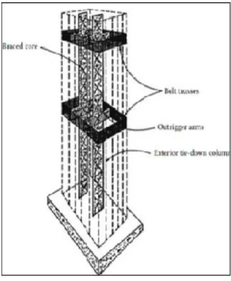
Outriggers are the horizontal members which resists lateral loads by mobilizing axial stiffness of perimeter column by connecting them to the core of the structure. When lateral loads acts on the structure, column restrained outriggers resists the rotation by inducing tension force on windward columns and compression force on leeward columns thereby generating a restoring tension-compression couple to resist core overturning moment and lateral deflection. This system can work efficiently for buildings upto 150 stories [1].
1.2 Challenges Associated with Outriggers
Outriggers occupying large vertical space upto 2-3 stories deep interferes with floor area in a building and restricts space utilization on these floors.
Outriggers connecting core and distant columns undergo additional stress due to differential vertical shortening between them.
The connections between core and outriggers needs to be properly studied and designed especially when the two are made up of different materials.
[image:1.595.317.549.417.699.2]
© 2017, IRJET | Impact Factor value: 5.181 | ISO 9001:2008 Certified Journal | Page 1807
2. METHODOLOGY
A structure with two outriggers is analyzed and then a single outrigger system with slabs and belt truss is found out which will be equivalent to two-outrigger system in its lateral stiffness. In this manner, multiple outrigger system can be reduced to single outrigger and its disadvantage of occupying large space can be avoided
3. MODEL DETAILS
Plan dimension : 27X24 m Typical storey height : 3.5m No. of storey : 40
Beam Details Breadth – 230mm Depth – 500mm
Column Details Breadth – 750mm Depth -750mm Concrete Grade : M-40 Steel Grade : Fe-250
Wind load (IS 875(Part-3)-1987) Design speed – 44m/s
Terrain Category – 2 Structural Class – B
Seismic load (IS 1893(Part-1):2002) Zone 3 – 0.16
Importance factor – 1.5 Soil type – Medium Reduction factor – 3
Following Different Models Have Been Prepared
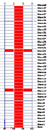
Case1: Two-Outrigger system with Core and Outriggers -300mm thick
Outriggers placed at ⅓rd and ⅔rd height of the
building i.e at 13th and 26th floor according to
Taranath thumb rule[2] (Fig. 1&2)
[image:2.595.404.485.114.337.2]Fig -1: Plan
Fig -2: Elevation
Case2: Single outrigger system with Core -300mm thick
Variation of relative flexural rigidity between outrigger and core (γ) = (EI)o/(EI)core and location of the outrigger in the above same plan and elevation (Fig -1&2).
(γ)
The location of outrigger (Hs/H) is varied as
0.25,0.5,0.75,1 for each value of (γ).
0.25
0.5
0.75
1
1.25
Case 3 : Following Floor systems are added
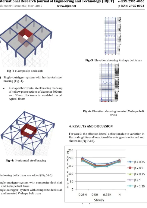
1) Single-outrigger system with composite deck slab (Fig -3).
[image:2.595.45.548.420.787.2]© 2017, IRJET | Impact Factor value: 5.181 | ISO 9001:2008 Certified Journal | Page 1808
Fig -3 : Composite deck slab
2) Single–outrigger system with horizontal steel bracing (Fig -4).
X-shaped horizontal steel bracing made up of hollow pipe sections of diameter 500mm and 30mm thickness is modeled on all typical floors
Fig -4: Horizontal steel bracing
Case4: Following belts truss are added (Fig 5&6)
Single outrigger system with composite deck slab and X-shape belt truss
Single outrigger system with composite deck slab and inverted V-shape belt truss
Fig -5 :Elevation showing X-shape belt truss
Fig -6: Elevation showing inverted V-shape belt truss
4. RESULTS AND DISCUSSION
For case 3, the effect on lateral deflection due to variation in flexural rigidity and location of the outrigger is obtained and shown in (Fig 7 &8).
0
50
100
150
200
250
0.25H
0.5H
0.75H
H
β = 0.25
β = 0.5
β = 0.75
β = 1
β = 1.25
Storey
Level
[image:3.595.80.264.419.569.2]D
e
f
l
e
c
t
i
o
n
[image:3.595.221.562.530.734.2]© 2017, IRJET | Impact Factor value: 5.181 | ISO 9001:2008 Certified Journal | Page 1809
Fig -8: Variation of lateral deflection for seismic load
Fig-7 & Fig-8 indicates that deflection decreases by increasing outrigger rigidity. It is observed that the maximum reduction of 29% and 25% is obtained when outrigger is placed at mid-height of the building for wind and seismic case respectively. Top displacement gets reduced to 6.2% and 3.31% by varying ‘γ’ from 0.25 to 0.5 and 0.5 to 0.75 respectively. It is observed that any further increase in flexural rigidity has relatively less effect in reducing deflection. Hence an increase in relative flexural rigidity to 0.75 and locating single outrigger at 0.5H is taken as the most optimum condition.
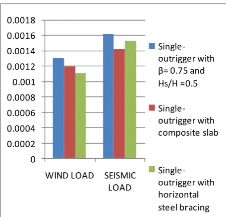
For Case 3, effects of adding composite deck slabs and horizontal steel bracing to the lateral deflection is shown in Chart -1 and Chart -2
0 20 40 60 80 100 120 140 160 180
WIND LOAD SEISMIC LOAD
Single-outrigger with β= 0.75 and Hs/H =0.5 Single-outrigger with composite deck slab Single-outrigger with horizontal steel bracing
Chart -1: Lateral deflection due to wind and seismic load
It is noticed that including floor diaphragms reduces lateral deflection and makes the structure stiffer. A reduction upto 6.85% and 2.67% is gained by adding composite slabs for wind and seismic load respectively. Horizontal steel bracing reduces deflection due to winds to 15% but it increases to 10% for seismic case due to an increase in buildings overall weight. 0 0.0002 0.0004 0.0006 0.0008 0.001 0.0012 0.0014 0.0016 0.0018
WIND LOAD SEISMIC LOAD
Single-outrigger with β= 0.75 and Hs/H =0.5 Single-outrigger with composite slab Single-outrigger with horizontal steel bracing
Chart -2 Storey drift due to wind and seismic load
A similar trend in the reduction of storey drift is also observed. A maximum reduction of 22.26% storey drift due to wind load and 12.15% due to seismic load is obtained.
For Case 4, results are found by adding belt truss and its effect on different parameters is shown in Chart -3 and Chart-4 112 114 116 118 120 122 124 126 128 130
WIND LOAD SEISMIC
LOAD
Single outrigger with composite slab and X-shape belt truss
Single outrigger with composite slab and inverted V-shape belt truss
[image:4.595.39.256.507.694.2]© 2017, IRJET | Impact Factor value: 5.181 | ISO 9001:2008 Certified Journal | Page 1810 0 0.0002 0.0004 0.0006 0.0008 0.001 0.0012 0.0014 WIND LOAD SEISMIC LOAD Single outrigger with composite slab and X-shape belt truss Single outrigger with composite slab and inverted V-shape belt truss
Chart -4: Storey drift due to wind and seismic load
A minor difference of 0.45% between performance of X and inverted V-shape towards lateral stiffness is observed . But it is clearly seen that X shape gives more stability to the structure compared to inverted V-shape.
Type of structure Lateral Deflection (mm) due to wind load
Lateral Deflection (mm) due to seismic load
Two-outrigger system
126 131
Single-outrigger system
146 150
Single-outrigger system with composite deck slab
136 146
Single-outrigger system with composite deck slab and X-shape belt truss
[image:5.595.102.555.46.362.2]118.47 128.9
Table-1: Comparison of lateral deflection for different structures
Type of structure Storey Drift due to wind load
Storey Drift due to seismic load
Multi-outrigger system
0.001248 0.001321
Single-outrigger system
0.001298 0.001613
Single-outrigger system with composite deck slab
0.001194 0.001417
Single-outrigger system with composite deck slab and X-shape belt truss
0.001057 0.001273
Table -2: Comparison of storey drift for different structures
From Table-1 and Table 2, it can be seen that single outrigger system with slabs and belt truss is found to have equal lateral stiffness compared to the two outriggers system. Hence the optimization process adopted is found to be feasible and effective.
5. CONCLUSIONS
1) When lateral deflection is considered providing a single outrigger at mid height of a building is found to be the optimum location for both wind and seismic loads.
2) Floor diaphragms provided in the form of composite deck slab and horizontal steel bracing enhances building lateral behaviour.
3) The maximum reduction of 15% due to wind loads by horizontal steel bracing and 2.67% due to seismic loads by composite slabs is achieved.
4) Further increase in lateral stiffness is obtained by adding belt truss on outrigger floors . X-shaped is found to have performed better than inverted V-shape.
[image:5.595.31.295.401.692.2]© 2017, IRJET | Impact Factor value: 5.181 | ISO 9001:2008 Certified Journal | Page 1811
REFERENCES
[1]. Mir M.Ali, Kyoung Sun Moon (2007) “Structural Developments in Tall buildings- Current Trend and Future Scope”.
[2]. Bungale S. Taranath (2004) “ Wind and Earthquake Resistant Buildings”.
[3]. K.L. Chang , C.C. Chen (2008) “ Outrigger System Study For Tall Building Structure with Central Core and square Floor Plate”.
[4]. S.M. Sayeed , Ghulam Ahmed (2013) “Effect of increased slab stiffness and outrigger system on Flat slab RC building" .
[5].Kiran kamath, Avinash A.R. and S. Upadhyaya(2014) “A Study on the performance of multi-outrigger structure subjected to seismic loads”.
[6]. Kiran Kamath,N. Divya and Asha U Rao (2012) “Optimum Positioning of Outrigger to Reduce Differential Column Shortening Due to Long Term Effects in Tall Buildings”.
[7]. Wind loads (IS: 875 Part-3) -1987