© 2017, IRJET | Impact Factor value: 5.181 | ISO 9001:2008 Certified Journal | Page 1873
Analysis of fault detection and its location using microcontroller for
underground cables
1
Sahana S ,
2Harish Kumar B M,
3Anu S M
4Vani H V,
5Sudha T,
6Prashanth Kumar H K
1,2,3
U.G Student, Department of EEE, SJMIT, Chitradurga, Karnataka, INDIA
4,5,6Associate Professor, Department of EEE, SJMIT, Chitradurga, Karnataka, INDIA
---***---Abstract -
Underground cables are prone to a wide variety of faults due to underground conditions, wear and tear, rodents etc. Also detecting fault source is difficult and entire line is to be dug in order to check entire line and fix faults. So here we propose cable fault detection over IOT that detects the exact fault position over IOT that makes repairing work very easy. The repairmen know exactly which part has fault and only that area is to be dug to detect the fault source. This saves a lot of time, money and efforts and also allows to service underground cables faster. We use IOT technology that updates the monitored fault information to internet. The system detects fault with the help of potential divider network laid across the cable. Whenever a fault gets created at a point shorting two lines together, a specific voltage gets generated as per the resistors network combination. This voltage is sensed by the microcontroller and is updated to the user. The information conveyed to the user is the information regarding faults detection. The microcontroller retrieves the fault line data and displays over LCD display, also it transfers this data over internet to display on Gmail server.Key Words:
IOT technology, LCD, microcontroller.
Potential divider
1. INTRODUCTION
The paper uses the standard concept of Ohms law i.e., when a low DC voltage is applied at the feeder end through a series resistor (Cable lines), then current would vary depending upon the location of fault in the cable. In case there is a short circuit (Line to Ground), the voltage across series resistors changes accordingly, which is then fed to an ADC to develop precise digital data which the programmed microcontroller of 8051 family would display in kilometers. The project is assembled with a set of resistors representing cable length in KM’s and fault creation is made by a set of switches at every known KM to cross check the accuracy of the same. The fault occurring at a particular distance and the respective phase is displayed on a LCD interfaced to the microcontroller.
Till last decades cables were made to lay overhead & currently it is lay to underground cable which is superior to earlier method. Because the underground cable are not affected by any adverse weather condition such as storm, snow, heavy rainfall as well as pollution. But when any fault occur in cable, then it is difficult to locate fault. So we will move to find the exact location of fault. Now the world is become digitalized so the project is intended to detect the location of fault in digital way.
The underground cable system is more common practice followed in many urban areas. While fault occurs for some reason, at that time the repairing process related to that particular cable is difficult due to not knowing the exact location of cable fault.
Fault in cable is represented as:
• Any defect,
• Inconsistency,
• Weakness or non-homogeneity that affects performance of cable
• Current is diverted from the intended path, For most of the worldwide operated low voltage and medium voltage distribution lines underground cables have been used from many decades. To reduce the sensitivity of distribution networks to environmental influences underground high voltage cables are used more and more. Underground cables have been widely used in power distribution networks due to the advantages of underground connection, involving more security than overhead lines in bad weather, less liable to damage by storms or lightning. It is less expensive for shorter distance, eco- friendly and low maintenance.
But if any fault occur in cable, then it is difficult to locate fault. So this project is used to detect the location of fault in digital way. The requirement of locating the faulty point in an underground cable in order is to facilitate quicker repair, improve the system reliability and reduced outage period. The underground cable system is very useful for distribution mainly in metropolitan cities, airport and defense
© 2017, IRJET | Impact Factor value: 5.181 | ISO 9001:2008 Certified Journal | Page 1874 million telephone and cable TV lines, and it’s no wonder
hurricanes, tornadoes, fires and ice storms are wreaking havoc on the electrical systems each year.
This causus the utility outages that last days, weeks and longer. Power outages over extended periods present major health and safety concerns and economic losses.
Concerns about the reliability of overhead lines, increases in their maintenance and operating costs, and issues of public safety and quality-of-life are leading more and more utilities and municipalities to the realization that converting overhead distribution lines to underground is the best way to provide high-quality service to their customers. For utility companies, undergrounding provides potential benefits through reduced operations and maintenance (O&M) costs, reduced tree trimming costs, less storm damage and reduced loss of day-to-day electricity sales when customers lose power after storms.
Creative funding options are often available to make the goal of undergrounding a reality. The underground cable system is very important for distribution especially in metropolitan cities, airports and defense service.
Types of Faults
A fault in a cable can be classified into different types such as
Open Circuit Fault: This type of fault is better than short circuit fault, because when the open circuit fault occurs, then the flow of current through an underground cable becomes zero. This fault can be occurred by disruption in conducting path. Such faults occur when one or more phase conductors break
Short Circuit Fault: Short circuit fault can be divided into two types, namely symmetrical and unsymmetrical faults
In symmetrical fault, three phases are short circuited in this type of fault. This type of fault is also called as three phase fault due to this reason.
In unsymmetrical fault, the magnitude of the current is not equal and displaced by 120 degrees. Temperature. Most environmental sensors were developed from sensors designed for industrial applications such as process control refining, milling, distilling, etc. Therefore many environmental sensors are designed with the same characteristics as industrial sensors such as 4-20 mA output & 12 VDC power supply.
2 LITERATURE SURVEY
[1] Jitendra pal singh, sanjana singh, toshika singh & mohd. Shahrukh. ‘underground cable fault distance locator’.
In this paper, a way for sleuthing underground cable fault distance locator is done by using microcontroller. The target of this project is to work out the gap of underground cable fault through base station in kilometers. It uses the straight forward conception of ohm’s law, voltage drop can vary counting on the length of fault in cable, since the current varies. A group of resistors are used to represent the length of cable in kilometers and a dc voltage is fed at one end and the fault is detected the change in voltage using analog to voltage converter. The fault occurring at what distance is shown on LCD which is interfaced with the microcontroller that is used to make the necessary calculations.
[2] Priyanka.R and B.Priya. "Underground Cable Fault Detection".
In this paper to detect a fault in an underground cable is still a challenging task in power system. In order to detect an underground cable fault, the standard concept of OHM’S LAW is used. This idea is used to determine resistive variation, short circuit fault, open circuit fault .This project provides accuracy in determining the exact location of fault, when a low DC voltage is applied at the feeder end through a series resistor (Cable lines), then current would vary depending upon the location of fault in the cable from the base station. This project provides detection of fault and also indication of cable’s temperature at varying voltage using a developed prototype from a microcontroller family. In the hardware setup we use the ARM 11 MSP430 microcontroller launch pad and a low cost low power 2.4Ghz transceiver and a readable current sensor. We can use X-CTU and MATLAB coding for detecting.
[3] B. Clegg, Underground Cable Fault Location. New York: McGrawHill, 1993.
© 2017, IRJET | Impact Factor value: 5.181 | ISO 9001:2008 Certified Journal | Page 1875
3 BLOCK DIAGRAM
Fig1: Proposed Block Diagram
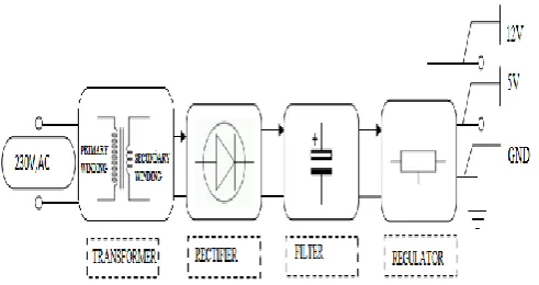
3.1 Power supply unit
This section needs two voltages viz., +12 V & +5 V, as working voltages. Hence specially designed power supply is constructed to get regulated power supplies.
Fig 2: Power Supply circuit diagram
3.2 Over Voltage and Under Voltage
When the voltage in a circuit or part of it is raised above its upper design limit, this is known as over voltage. When the voltage in a circuit or part of it is raised above its lower design limit, this is known as under voltage This sensor will be used to check whether the over or under voltage occurs to the circuit. If occurs then it will activates the buzzer to indicate over or under voltage has occurred.
Fig 3: Circuit Diagram of Over Voltage and Under Voltage
3.3
Monostable Multivibrators
Monostable Multivibrators have only one stable state (hence their name: “Mono”), and produce a single output pulse when it is triggered externally. Monostable Multivibrators only return back to their first original and stable state after a period of time determined by the time constant of the RC coupled circuit.
3.4
Microcontroller
Microcontroller is computer processor based RISC architecture. A RISC-based computer design approach means MC processors require significantly fewer transistors than typical processors in average computers. This approach reduces costs, heat and power use. The low power consumption of MC processors has made them very popular. The MC architecture (8-bit) is the most widely used architecture in mobile devices, and most popular 8-bit one in embedded systems.
3.5
GSM
GSM Shield (SIM 900a): The SIM900 which is a complete Quad-band GSM/GPRS solution comes in a SMT module which can be embedded in customer applications. Featuring an industry-standard interface, the SIM900 delivers GSM/GPRS 850/900/1800/1900MHz performance for Data, voice, SMS and Fax in a small form factor and with low power consumption. SIM900 can fit almost all the space requirements in the M2M application with dimensions of 24mm x 24mm x 3 mm. SIM900 is designed with a very powerful single-chip processor integrating AMR926EJ-S core. Quad - band GSM/GPRS module with a size of 24mmx24mmx3mm, SMT type suit for customer application, An embedded Powerful TCP/IP protocol stack Based upon mature and field-proven platform, backed up by our support service, from definition to design and production GSM, which
1
0
K
4
.
7
K
1
0
K
4
.
7
K
R
L
5 . 6 v Z e n e r d i o d e
5 . 6 v Z e n e r d i o d e
5
4
7
5
4
7
Vc c 5v Vc c 12 v
N
/
O
P
o
l
e
N
/
C
R
L
N
/
O
[image:3.595.40.286.435.565.2]© 2017, IRJET | Impact Factor value: 5.181 | ISO 9001:2008 Certified Journal | Page 1876 stands for Global System for Mobile communications, reigns
as the world’s most widely used cell phone technology. Cell phones use a cell phone service carrier’s GSM network by searching for cell phone towers in the nearby area.
4
METHODOLOGY
This paper is designed to achieve monitoring of underground cable and to provide information about detected fault. Over voltage, under voltage, short circuit and open circuit conditions will be monitored by respective sensors.
If any faults occurs that will be detected by respective sensors and sends that signal to controller via Monostable Multivibrators and interfacing stage i.e buffer, driver and relay unit. buffer is used for temporary storage, driver is used to drive the relay and relay for switching. Controller analyses the received signal and activates the GSM modules to send information about monitored parameter to concern person. Controller as well activates the alerting system via interfacing stage i.e buffer, driver and relay unit. In the transmitting section, the corresponding voltage drop is fed into the controller MSP430 launch pad. The launch pad consists of a 12bit Analog to Digital converter. This converter provides precise accuracy for about 3.3V. The 12bitAnalog to digital converter converts the voltage into digital signal which is received from the current sensor. The controller MSP430 launch pad makes necessary calculations regarding the fault location. This data is then transmitted to the receiving section. The receiving section consists of a low cost low power wireless controller, transceiver and a display. The data’s are fed from the transmitting section to the transceiver. The transceiver is interfaced with the display i.e PC. The display shows the status of the cable at each phase. Also the distance of the cable at particular phase is displayed in case of any fault. The corresponding changes in the voltage and current help us to determine the type of fault in the cable. The data’s are displayed using MAT LAB coding. The resistive variation, current reading can be obtained.
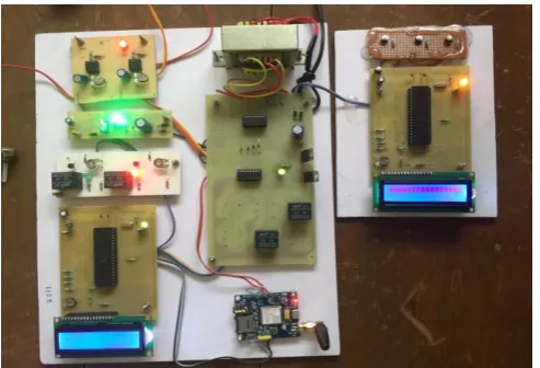
5 DESIGN AND DEVELOPMENT OF HARDWARE
The 230V supply is first stepped down to 12V AC using a stepdown transformer. This is then converted to DC using centre tap full wave rectifier. The AC ripples is filtered out by using a capacitor and given to the input pin of this regulator. At output pin of this regulator we get a constant 5v DC which is used for microcontroller and other ICs in this project.Fig 4: Hardware connection diagram
This project is designed to achieve monitoring of underground cable and to provide information about detected fault. Over voltage, under voltage, short circuit and open circuit conditions will be monitored by respective sensors. If any faults occur that will be detected by respective sensors and sends that signal to controller via Monostable Multivibrators and interfacing stage i.e buffer, driver and relay unit.
Buffer is used for temporary storage and avoids the fluctuations which is present in the input and which is fed to driver. Driver is used to drive the relay where the output is complement of input which is applied to the drive but current will be amplified. Relay is used for switching and also used to drive the load connected across the relay and the output of the relay can be connected to controller or load for further processing. Controller analyses the received signal and activates the GSM modules to send information about monitored parameter to concern person. Controller as well activates the alerting system via interfacing stage i.e buffer, driver and relay unit.
5
ADVANTAGES
[image:4.595.308.555.97.265.2]© 2017, IRJET | Impact Factor value: 5.181 | ISO 9001:2008 Certified Journal | Page 1877 Primary benefits most often cited can be divided into
four areas:
Potentially-Reduced Maintenance and Operating Costs: Lower storm restoration cost
Lower tree-trimming cost
Improved Reliability: Increased reliability during severe weather wind related storm damage will be greatly reduced for an underground system, and areas not subjected to flooding and storm surges experience minimal damage and interruption of electric service. Less damage during severe weather
Far fewer momentary interruptions
Improved utility relations regarding tree trimming Improved Public Safety:
Fewer motor vehicle accidents Reduced live-wire contact injuries Fewer Fires
6 DISADVANTAGES
The main disadvantage is that the underground cables have higher initial cost and insulation problems at high voltages. Another main drawback is that, if a fault does occur, it is difficult to locate and repair the fault because the fault is invisible
.
7 APPLICATIONS
Its main application is the detection of underground cable fault which is very hard to detect as it is not possible to see such faults which are quite possible in the case of overhead transmission line. So for such cases our project is very helpful as the distance at which the fault has occurred can be calculated and then further action regarding the fault can be taken to overcome them.
8 CONCLUSION
The hardware model of Underground Cable Fault Locator is implemented and favorable results were brought forward. This hardware model can locate the exact fault location in an underground cable. Further this project can be enhanced by using capacitor in an AC circuit to measure the impedance which can even locate the open circuited cable, unlike the short circuited fault only using resistors in DC circuit as followed in the above proposed project. Underground cables are prone to a wide variety of faults due to underground conditions, wear and tear, rodents etc. Also detecting fault source is difficult and entire line is to be dug in order to check entire line and fix faults. So here we propose cable
fault detection over IOT that detects the exact fault position over IOT that makes repairing work very easy. The repairmen know exactly which part has fault and only that area is to be dug to detect the fault source. This saves a lot of time, money and efforts and also allows to service underground cables faster. We use IOT technology that updates the monitored fault information to internet. The system detects fault with the help of potential divider network laid across the cable. Whenever a fault gets created at a point shorting two lines together, a specific voltage gets generated as per the resistors network combination. This voltage is sensed by the microcontroller and is updated to the user. The information conveyed to the user is the information regarding faults detection.
REFERENCES
[1] Jitendra pal singh, sanjana singh, toshika singh & mohd. Shahrukh―underground cable fault distance locator. International Journal of Scientific Research and Management Studies (IJSRMS) Vol 3 , pg: 21-26
[2] Priyanka R, Priya B "Underground Cable Fault Detection" Published in International Journal of Trend in Research and Development (IJTRD), ISSN: 2394-9333, Volume-3 | Issue-3 , June 2016, URL:
[3] M.-S. Choi, D.-S. Lee, and X. Yang, ―A line to ground fault location algorithm for underground cable system,‖ KIEE Trans. Power Eng., pp. 267–273, Jun. 2005.
[4] E. C. Bascom, ―Computerized underground cable fault location expertise, ‖in Proc. IEEE Power Eng. Soc. General Meeting, Apr. 10–15,1994, pp. 376–382.J. Clerk Maxwell, A Treatise on Electricity and Magnetism, 3rded., vol. 2. Oxford: Clarendon, 1892, pp.68–73.
[5] K.K. Kuna, Prof. K. Warwick, ―Real-time expert system for fault location on high voltage underground distribution cables‖, IEEE PROCEEDINGS-C, Vol. 139, No. 3, MAY 1992.
[6] J.Densely, ―Ageing mechanisms and diagnostics for power cables—an overview,‖ IEEE Electr. Insul. Mag., vol. 17, no. 1, pp. 14–22, Jan./Feb. 2001.
[7] T. S. Sidhu and Z. Xu, ―Detection of incipient faults in distribution underground cables‖, IEEE Trans. Power Del., vol. 25, no. 3, pp. 1363–1371, Jul. 2010.
© 2017, IRJET | Impact Factor value: 5.181 | ISO 9001:2008 Certified Journal | Page 1878 [9] Md. Fakhrul Islam, Amanullah M T Oo, Salahuddin. A.
Azad1 , ―Locating Underground Cable Faults: A Review a nd Guideline for New Development‖ , 2013 IEEE
[10] Sawatpipat, P., Tayjasanant, T., “Fault classification for Thailand’s transmission lines based on discrete wavelet transform”, International Conference on Electrical Engineering/Electronics Computer Telecommunications and Information Technology (ECTI-CON), Page(s): 636 – 640, 2010.
[11] M. Jaya Bharata Reddy, D. Venkata Rajesh, D.K. Mohanta,"Robust transmission line fault classification using wavelet multi-resolution analysis.", Computers & Electrical Engineering, Volume 39, Issue 4, Pages 1219-1247. , May 2013
[12] Ali Rafinia, Jamal Moshtagh, " A new approach to fault location in three-phase underground distribution system using combination of wavelet analysis with ANN and FLS ", International Journal of Electrical Power & Energy Systems, Volume 55, Pages 261-274 , February 2014.
BIOGRAPHIES
Vani H V
Associate Professor,
Dept. of EEE, SJMIT, Chitradurga- Karnataka, INDIA
Prashanth Kumar H K Assistant Professor,
Dept. of EEE, SJMIT, Chitradurga, Karnataka, INDIA
Sudha T
Assistant Professor,
Dept. of EEE, SJMIT, Chitradurga, Karnataka, INDIA
Sahana S U.G Student,
Dept. of EEE, SJMIT, Chitradurga, Karnataka, INDIA
Anu S M U.G Student,
Dept. of EEE, SJMIT, Chitradurga, Karnataka, INDIA
Harish Kumar B M
U.G Student,
Dept. of EEE, SJMIT, Chitradurga,
Karnataka, INDIA