© 2018, IRJET | Impact Factor value: 6.171 | ISO 9001:2008 Certified Journal | Page 3427
Design and Strength Validation of Front Car Bumper Using Composite
Material
Vishwanatha R H
1, Ajith A
2, Anand N
3, Punith Raju K B
4, Vasantha Kumar
51
Assistant Professor, Department of Mechanical Engineering, PNS Institute of Technology, Nelamangala,
Bangalore, India
2345
U.G. Student, Department of Mechanical Engineering, PNS Institute of Technology, Nelamangala, Bangalore,
India.
---***---Abstract
-Bumper is being one of the most important part and support maximum functions like energy absorption while the energy being transferred to the vehicle body. Bumpers are legally required on all vehicles. In this work, a front car bumper is designed by using the software CATIA V5 R20. It is then imported into FEM package of NASTRAN in HYPERMESH. And various analysis is done such as modal analysis (vibration analysis), static analysis i.e., impact force analysis stress analysis and strength analysis. The materials used for this analysis are carbon fiber reinforced plastic and epoxy resin having the composition 60% of CFRP and 40% of epoxy resin. The results are then compared with the conventional material such as steel. From all these analysis and comparison, it can be concluded that the composite materials CFRP (Carbon Fiber Reinforced Plastic) and Epoxy-resin are suitable for use in the cars.Key Words
:
Front bumper, Impact analysis, Static analysis, Nastran, Catia.
1. INTRODUCTION
Car accidents are happening every day. Most drivers are convinced that they can avoid such troublesome situations. Improvement in the safety of automobiles is essential to decrease the number of accidents and injuries. Automotive bumper beam is one of the key systems in passenger’s car. Bumper system is designed to prevent or reduce physical damage to the front or rear ends of passenger motor vehicles in collision condition. Bumper protects the hood, trunk, grill, fuel tank, exhaust and cooling system as well as safety related equipment’s such as parking lights, head lamps and tail lights. Automobile bumpers have been implemented for two reasons – to allow the car to sustain a low-speed impact without damage to the vehicle’s safety systems and to protect the passengers in the vehicle from the injury. The safety of the passengers during vehicle crashes can be ensured to a certain limit by using good bumpers. Bumpers are fixed on the front and on the back side of a car and serve as its protection. They reduce the effects of collisions with other cars and objects due to their large deformation zones. The bumpers are designed and shaped in order to deform it and absorb the force during a collision.
1.1 COMPOSITE BUMPERS
In recent years, the automotive industry has advanced a great deal and composite materials have played a large role in this revolution. Various composite materials have been experimented in most parts of cars. Manufacturers fill polymers with particles in a bid to improve the toughness and stiffness of the materials, as a means of enhancing their barrier properties as well as enhancing their resistance to fire ignition, or simply to reduce costs. The addition of particulate fillers can lead to drawbacks such as brittle or opaque composites.
1.2 CARBON FIBER REINFORCED PLASTIC BUMPER
Carbon fiber reinforced plastic is an extremely strong and light fiber-reinforced plastic which contains carbon fibers. CFRPs can be used wherever high strength-to weight ratio and rigidity are required, such as aerospace, automotive, civil engineering, sports goods and an increasing number of other consumer and technical applications. The binding polymer is often a thermoset resin such as epoxy, but other thermoset or thermoplastic polymers, such as polyester, vinyl ester or nylon, are sometimes used.
1.3 STEEL BUMPERS
Originally plated steel was used for entire body of a car, including the bumper. This material worked well, as it was very strong in a crash. As car engine design has improved, steel bumpers have pretty much disappeared for anything except classic cars. Steel bumpers have many advantages such as their relatively high load carrying capacity and high ductility. However, this gives a low strength-to-weight ratio. Car manufacturers have stated that using steel adds to the aesthetic as well as minimizes life cycle costs. Steel is heavy and adds weight to the vehicle, which can impact your vehicles ride quality. It is also very hard to install the bumper due to weight. The surface of steel can rust and oxidize if not properly cared for. If steel bumper does somehow get dented, it’s difficult to repair.
1.4 EPOXY RESIN
© 2018, IRJET | Impact Factor value: 6.171 | ISO 9001:2008 Certified Journal | Page 3428 plasticizers and fillers can be added to produce epoxies with
wide ranges of properties from viscosity to impact. Even with its high cost when compared to other polymer matrices, its popularity overshadows the rest.
2. LITERATURE SURVEY
Literatures related to impact are studied by many researchers. It was absorbed that major injury due to impact velocity affects to the car bumper.
Dubem Ezekwem [1] had studied and analyzed about the use of composite materials in frontal car bumper. Materials such as nylon-6 nano composite and polyethylene/palm kernel shell-iron filings composites are used.The mechanical properties of these materials are then compared with conventional car bumper material such as Aluminium and Steel. This comparison showed a reduction in weight, cost and environmental impact and also have some disadvantages such as difficulty in mass production and sophistication(quality) of the production process were also noted.
Bhavesh A. Bohra, Prof. D. B. Pawar [2] In this review, the front bumper is designed and analyzed during impact, the materials used are ABS (Acrylonitrile Butadine Styrene) and PEI (Polyetherimide).ABS plastic is very tough and resilient, has high impact strength, good chemical resistance and is nontoxic and taint free. ABS plastic has low density compared to PEI. Hence, ABS material has chosen and comparatively best than the PEI.
S Seenuvas, N Nagendran, N Gayathri, T V B Babu, R Manjunathan [3] In this review they studied about the energy absorption analysis in front bumper of a car. The bumper absorbs impact energy and transfers to opposite direction to the impact. The materials used in this are carbon fiber foam composite, steel magma alloy, aluminium honey comb materials are used. Evolution has been done between this material and best one has been chosen based on the level of energy absorbed on bumper. Carbon fiber foam composite absorbs more impact when compared to other material in this study. Hence, carbon fibre foam composite is chosen.
Mr. Nitin S Motgi and Prof. S.B. Naik[4] They had studied about the Impact Analysis of Front Bumper. In this review, the material used for analyzing are aluminium and composite fascia, where aluminium having higher density than fascia. Finally, it is found that composite fascia is suitable from impact point of view.
Mahesh Kumar v. Dange, Dr. Rajesh B. Buktal, Dr. Nilesh R. Raykai[5] They have proposed about the design and analysis of an automotive front bumper. The material used is M220 (Martinsite 220 min tensile strength) formed in carbon steels. It can minimize the bumper deflection, impact force and stress distribution and also maximize the elastic strain energy. But it also has some disadvantages such as
high material cost compared to fiber glass and difficulty in mass production and also having high density.
Arun Basil Jacob, Arun kumar O.N[6] They emphasized that improving crashworthiness of an automobile bumper. This review proposes a new bumper model which has more crashworthiness than the existing bumper. They aim at improving crashworthiness of an automobile bumper. They selected TOYOTA CAMRY MODEL released in 2012. The bumper of the existing model had steel bumper. Two new designs were proposed in this review. Model containing Honeycomb inside the existing bumper being the first one and foam incorporated design as the second. The newly designed models namely foam and the honeycomb incorporated bumpers show better impact absorption capacity. The absorption capacity of the Honeycomb model is 11.26% and of foam model capacity is 6%. Foam is used for crashworthiness in the automobile industry for two main reasons. To fracture and break, absorbing the crash energy and to reinforce sheet metal and an overall light structure.
Alen John, Nidhi M B[7] In this review, the materials used in this analysis are aluminium 390 alloy, chromium coated mild steel and carbon composite. The analysis under dynamic loading shows this carbon composite has the max. Stress value and it is having the highest strength to weight ratio and producing deformation. From all these analyses it can be conclude that carbon composite is the best material and it can be used.
Lingam Jayashree, D Venkataramaniah, G Naveen Kumar [8] In this review the material used is long fiber reinforced thermoplastics. It is then compared to conventional material. The purpose of this project is to design a bumper which is to improve crashworthiness of bumper. From the above analysis it is concluded that long fiber reinforced thermoplastic material based is good. Then it is compared with other materials and natural fibers have good energy absorption capacity.
Pradeep Kumar Uddandapu[9] In this review material used is ABS plastic and PEI. The aim of this study is to analyze and to study the structure and material. In this research analysis is done for speed according to regulations and also by changing speed in this analysis. The density of ABS plastic and PEI is less than that of steel therefore the overall weight of car bumper is reduced. In this conclusion, comparing the results of ABS plastic and PEI with steel, the stress values are less for ABS plastic and for the other two materials, therefore ABS plastic is better for utilization comparing PEI.
© 2018, IRJET | Impact Factor value: 6.171 | ISO 9001:2008 Certified Journal | Page 3429 2.1 SUMMARY FROM LITERATURE SURVEY
From all the above literature survey, we come to know that weight reduction, cost and low impact are the three major aspects considered in designing of a car bumper. Various authors had done analysis for different materials and given their results and conclusions. From that point of view, we have designed the front car bumper and done the modal analysis (vibration analysis) and static analysis (impact, stress and strength analysis). And the materials used for this analysis are carbon fiber reinforced plastic with epoxy resin (composite material). And it is then compared with the conventional material i.e. steel. The formulated results obtained from the strength analysis for both the materials are then compared. And finally, from the results we can say that the design is safe and the conventional steel materials can be replaced by composite material i.e. carbon fiber reinforced plastic.
3. PROBLEM IDENTIFICATION
The current issue of the automobile industries is in reduction of weight and safety. And difficult in mass Production which includes high cost and in maintaining its quality. The main aim of our project is to overcome from the disadvantage of weight and the quality of the component. In this work, estimation of stress and deformation of steel and composite material by static analysis is done. And also, evaluate whether the design is safe or not.
3.1 OBJECTIVE
[image:3.595.309.549.153.403.2]The main aim of our project is to overcome from the disadvantage of weight and the quality of the component. Estimation of stress and deformation of steel and composite material by static analysis is done. And also, to evaluate whether the design is safe or not. Modal analysis to find the different modes and their natural frequencies in vibrational condition. Finally, comparative analysis is done between the steel and CFRP material.
Table -1: MATERIAL PROPERTIES
Properties STEEL CFRP
Density(kg/m3) 7.9E-09 1.8E-09
Young’s modulus(Gpa) 210 140
Poisson’s ratio 0.3 0.3
Ultimate Strength(Mpa) 570 1550
4. METHODOLOGY
We have newly designed the front car bumper using the CATIA V5 R20 software and it is then finely meshed using the HYPER MESH software and then the meshed model is imported to the ANALYSIS workbench to perform the modal analysis, static analysis and impact analysis by giving the corresponding Boundary conditions.
4.1 MODEL DESCRIPTION
The 2D view of the designed model is shown below with the dimensions specified. The data required for designing this model are:
THICKNESS : 2mm
TOTAL LENGTH : 344.61mm
Figure -1: Draft Model
4.2 GEOMETRY
Figure-2: 3D Bumper Model
[image:3.595.307.530.541.645.2]4.3 MESHED MODEL
Figure-3: Meshed model
FINITE ELEMENT MODEL DATA INFORMATION:
Total # of Grids (Structural) : 6444
Total # of Elements : 6074
[image:3.595.54.270.571.656.2]© 2018, IRJET | Impact Factor value: 6.171 | ISO 9001:2008 Certified Journal | Page 3430 CQUAD4 Elements : 5770
CTRIA3 Elements : 304
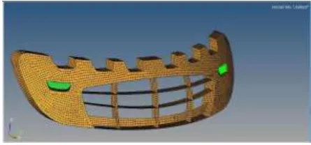
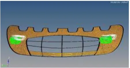
4.4 BOUNDARY CONDITIONS
[image:4.595.49.275.190.308.2]After the model is meshed; it is then subjected to different boundary conditions. The model is fixed at the two lamp positions as shown in figure.
Figure-4: Fixed at two lamp positions
5. Impact Analysis=
This analysis is done for the designed front car bumper model of CFRP material when the bumper is in stationary position.
[image:4.595.327.516.207.309.2]In this impact analysis is done, when gravitational force is acting in all the three directions i.e. XYZ
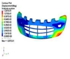
Figure-5: Displacement of the component
Figure-6: Maximum stress region
Combined_GRAV:
Maximum displacement is 0.390E-02 at grid 2776.
Maximum 2-D element stress is 0.531 in element 424.
5.1 Impact Analysis at 45km/hr
In this case, the impact analysis is done for CFRP material at 45kmph and the force acting on the bumper is 9810 KN.
Figure-7: Displacement of the component
Maximum displacement is 25.0 at grid 2772.
Maximum 2-D element stress is 0.259E+04 in element 8471.
Figure-8: Maximum stress region
6. STRENGTH ANALYSIS OF COMPOSITE MATERIAL
Strength analysis is done for the designed front bumper model of composite material i.e. (CFRP)
Carbon Fiber Reinforced Plastic Numerical method:
Factor of Safety (FOS) =
𝑈𝐿𝑇𝐼𝑀𝐴𝑇𝐸𝑆𝑇𝑅𝐸𝑁𝐺𝑇𝐻 / WORKING STRESS FOS = 𝑋𝑇 + 𝑌𝑇 / STRESS
FOS= 1550/447.43 = 3.46 > 1.5 Where,
[image:4.595.40.268.437.560.2]© 2018, IRJET | Impact Factor value: 6.171 | ISO 9001:2008 Certified Journal | Page 3431 YT = ultimate compression strength perpendicular in fiber
direction.
YC = ultimate compression strength perpendicular in fiber direction.
[image:5.595.320.468.79.202.2]Therefore, from the results obtained we can say that, the design is safe.
Figure-9: Displacement of the component Maximum displacement is 1.08 at grid 2588.
[image:5.595.56.257.181.292.2]Maximum 2-D element stress is 447. in element 366.
Figure-10: Maximum stress region
6.1 STRENGTH ANALYSIS OF STEEL MATERIAL
Strength Analysis of car bumper using steel material. Numerical method:
Factor of Safety (FOS) =
Factor of Safety =
= = 4.4 > 1.5
Where,
XT = ultimate tensile strength in fiber direction. XC = ultimate compression strength in fiber direction. YT = ultimate compression strength perpendicular in fiber direction.
[image:5.595.316.467.269.390.2]YC = ultimate compression strength perpendicular in fiber direction.
Figure-11: Displacement of the component
Maximum displacement is 0.121 at grid 2589.
Maximum 2-D element stress is 129. in element 8475.
Figure-12: Maximum stress region
7. MODAL ANALYSIS OF COMPOSITE MATERIAL
The modal analysis is done for the front bumper using composite material (CFRP).
The bumper is fixed in all DOF. And the resultant cut-off frequency is obtained for 6 modes and are shown below:
Mode:1
Freq: 368. Hz
Maximum deformation is 229. at grid 277
Figure-13: Displacement for Mode 1 Modal Analysis
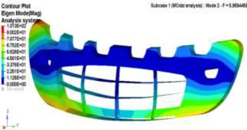
Mode:2
Freq: 448.Hz
[image:5.595.53.257.351.473.2] [image:5.595.316.552.571.690.2]© 2018, IRJET | Impact Factor value: 6.171 | ISO 9001:2008 Certified Journal | Page 3432 Figure-14: Displacement for Mode 2 Modal Analysis
Mode: 3
Freq: 592. Hz
[image:6.595.319.548.287.434.2]Maximum deformation is 282. at grid 6181
Figure-15: Displacement for Mode 3 Modal Analysis
Mode: 4
Freq: 669. Hz
[image:6.595.40.281.297.439.2]Maximum deformation is 313. at grid 2281.
Figure-16: Displacement for Mode 4 Modal Analysis
Mode: 5
Freq: 706. Hz
[image:6.595.322.505.492.614.2]Maximum deformation is 302. at grid 3069.
Figure-17: Displacement for Mode 5 Modal Analysis
Mode: 6
Freq: 731. Hz
Maximum deformation is 297. at grid 6676
Figure-18: Displacement for Mode 6 Modal Analysis
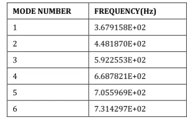
RESULTS OBTAINED:
Table-2: Modal Analysis of CFRP
7.1 MODAL ANALYSIS OF STEEL MATERIAL
Now, the modal analysis is done for the front bumper using steel material.
The bumper is fixed in all DOF. And the resultant cut-off frequency is obtained for 6 modes and are shown below:
Mode:1
Freq: 528. Hz
MODE NUMBER FREQUENCY(Hz)
1 3.679158E+02
2 4.481870E+02
3 5.922553E+02
4 6.687821E+02
5 7.055969E+02
[image:6.595.45.281.522.665.2]© 2018, IRJET | Impact Factor value: 6.171 | ISO 9001:2008 Certified Journal | Page 3433 Maximum deformation is 106. at grid 2770.
Figure-19: Displacement for Mode 1 Modal Analysis
Mode: 2
Freq: 597. Hz
[image:7.595.320.539.263.375.2]Maximum deformation is 101. at grid 6180
Figure-20: Displacement for Mode 2 Modal Analysis
Mode:3
Freq: 823.Hz
[image:7.595.36.278.321.448.2]Maximum deformation is 143. at grid 6181.
Figure-21: Displacement for Mode 3 Modal Analysis
Mode: 4
Freq: 871. Hz
Maximum deformation is 141. at grid 2954
Figure-22: Displacement for Mode 4 Modal Analysis
Mode: 5
Freq: 927. Hz
Maximum deformation is 118. at grid 3159.
Figure-23: Displacement for Mode 5 Modal Analysis
Mode:6
Freq: 995.Hz
Maximum deformation is 130. at grid 6674.
Figure-24: Displacement for Mode 6 Modal Analysis
RESULTS OBTAINED:
MODE NUMBER FREQUENCY (Hz)
1 5.284432E+02
2 5.969445E+02
3 8.234981E+02
4 8.713997E+02
5 9.265196E+02
6 9.948383E+02
[image:7.595.321.537.446.562.2] [image:7.595.46.268.524.660.2]© 2018, IRJET | Impact Factor value: 6.171 | ISO 9001:2008 Certified Journal | Page 3434
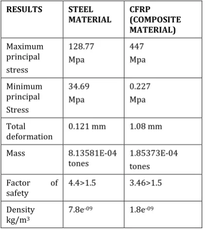
8. COMPARATIVE ANALYSIS
Final, comparison between steel and CFRP from the results obtained.
RESULTS STEEL
MATERIAL CFRP (COMPOSITE
MATERIAL)
Maximum principal stress
128.77 Mpa
447 Mpa
Minimum principal Stress
34.69 Mpa
0.227 Mpa
Total
deformation 0.121 mm 1.08 mm
Mass 8.13581E-04
tones 1.85373E-04 tones
Factor of
safety 4.4>1.5 3.46>1.5 Density
kg/m3
7.8e-09 1.8e-09
[image:8.595.57.268.137.374.2]
Table-4: Comparison between steel and CFRP
9. CONCLUSION
The results obtained by the strength analysis of CFRP material is then compared with the conventional material i.e. steel. We can say that the designed front bumper model is safe. And from this we come to know that steel material can be replaced with CFRP material.
REFERENCES
[1] Dubem Ezekwem had studied and analyzed about the use of composite materials in frontal car bumper. Loughborough University Aug.2016.
[2] Bhavesh A. Bohra, Prof. D. B. Pawar discussed about the comparative analysis of frontal car bumper during impact. Dept. Of Mechanical Engineering, Gawai Institute of Engineering and Technology, Darapur, Maharashtra, India. Vol.3, Issue 12, December 2014.
[3] S Seenu as, N Nagendran, N Gayathri, T V B Babu, R Manjunathan had studied about the energy absorption analysis in front bumper of a car. Dept. of mechanical engineering, Vel Tech High Tech Dr. Rangarajan Dr. Shakunthala Engineering college Chennai- 600062.
[4] Mr. Nitin S motgi, Prof. S.B. Naik, Prof. P.R. Kulkarni had studied about the Impact Analysis of Front Bumper. Walchand Institute of Technology, Solapur, India.Vol. 6 no.5 December 2013.
[5] Mahesh Kumar v. Dange, Dr. Rajesh B. Buktal, Dr. Nilesh R. Raykai has proposed about the design and analysis of an automotive front bumper. Dept. Of Mechanical Engineering, Sardar Patel College of Engineering/Mumbai University, India Apr.2015.
[6] Arun Basil Jacob, Arun kumar O. N emphasized that improving crashworthiness of an automobile bumper. Dept. Of Mechanical Engineering, SNGCE, Kolenchery, Kerala.
[7] Alen john and Nidhi M B studied about the analysis of an automotive bumper used for a low passenger vehicle. P.G. scholar, Dept. of mechanical engineering, Mar Baselios college of Engineering and technology. Trivandrum, India.
[8] Lingam Ramyashree, D Venkataramaniah, G Naveen Kumar discussed about the impact analysis of frontal car bumper using long fiber reinforced thermoplastics. Balaji Institute of Engineering and Science, Warangal, Telangana, India. Vol.5 no.3 june 2015.
[9] Pradeep Kumar Uddandapu studied on impact analysis on car bumper by varying speeds using materials ABS plastic and poly ether imide by FEM. Assistant professor, Dept. of Mechanical Engineering, K.S.R.M College of Engineering. Kadapa. Andhra Pradesh, India. Vol-3 issue 1, jan-feb 2013.