A Rotating Reference Signal Based on Nonlinear Control
for Multi-bus Single Phase Micro-grids
Moslem Dehghani
*, Taher Niknam, Mohammad-Reza Tavana, Ghasem Asadi
Department of Electrical Engineering, Shiraz University of Technology, Iran
Copyright ©2016 by authors, all rights reserved. Authors agree that this article remains permanently open access under the terms of the Creative Commons Attribution License 4.0 International License
Abstract
In islanding Micro-Grids (MGs), distributed generation units are in charge of controlling voltage, frequency, and current of the grid on their own without any assistance from the main grid. Therefore, it is of utmost importance to select and design a controller that is robust against disturbances and load variations. In this study, a new sliding mode controller with a rotating reference voltage algorithm is proposed which improves the load sharing between distributed generators (DGs) in an islanded mode MG. In the proposed algorithm, the amplitude of the reference voltage signal of the controller is adaptively modified to improve the performance and convergence rate of the controller. As a case study, the proposed strategy is studied based on the assumption that there are three DGs in the grid. One of the DGs is in charge of regulating voltage and frequency based on a reference signals, and the two other DGs are responsible for load sharing and loads current control mode. The MG under study consists of three low voltage distributed generation units operating in parallel mode. In order to have a realistic case study, it is assumed that the MG consists of different types of loads such as resistive, inductive and nonlinear loads. Extensive simulations carried out in MATLAB environment indicate that the proposed framework is able to provide more desirable total harmonic distortion (THD), lower steady state error, and faster response compared with classic sliding mode controllers.Keywords Rotating Reference Signal, Sliding Mode
Controller, DC/AC Converter, Islanding Mode1. Introduction
In any occasions where electricity consumption is far from the main grid, such as remote villages/islands, or isolated communication stations, it is economically inefficient and/or technically difficult to deliver electricity via transmission lines. In such circumstances, an economically reasonable approach is to supply power in a form of islanding mode MG that contains renewable energy resources such as wind
turbines, fuel cells, photovoltaic generators and etc. [1]. In such islanding MGs, distributed generation units of the MG are in charge of controlling voltage, frequency, and current on their own without any assistance from the large main grid [1-3]. Therefore, it is crucial to design an appropriate controller to be robust against MG’s disturbances and load variations. The main goal of this paper is to propose a robust nonlinear controller for MGs.
It is desirable that an MG control (MGC) provides sinusoidal output currents and voltages (that is with low total harmonic distortion) in all operation modes [4]. Additionally, MGC is expected to be robust against grid disturbances, be efficient, of fast dynamic response, and provide proper voltage regulation. So far to achieve such features, many control approaches have already been proposed in the literature especially for pulse width modulation (PWM) based converters: proportional-integral-derivative (PID) control, robust control, model-based linear control, and internal model principle based control [5–7]. However, to be more precise, MGC is more of a nonlinear, time-variable system due to uncertainties caused by the operation mode transitions and DG disturbances. Accordingly, conventional control techniques are less likely to reach their ideal control objectives due to highly coupled nonlinearitied and multivariable structure of the system. In fact, majority of the conventional control techniques are able to provide acceptable performance only in some limited operating points. As a result, nonlinear controllers look to be more suitable candidates to overcome the uncertainties issues, and to guaranty global stability and better compensation [8].
in voltage-source rectifiers, which have proven high ability to provide fast dynamic response, quasi unity power factor operation as well as low current harmonic content.
Practically speaking, in the control theory, it is very difficult, if not impossible, to acquire an accurate and precise mathematical model of a system. This is mostly caused by variation in the parameters of the system, some other uncertainties, external disturbances and the limitation caused by detection methods [4]. Therefore, using robust control frameworks are superior over conventional control methods as they can handle such issues more successfully. In this framework, total sliding surface tries to decline the control error through a sliding motion for the state trajectory [16]. The proposed framework also uses fixed frequency PWM modulation. As a result, switching frequency remains constant, which is advantageous over variable switching strategies.
There have been lots of researches in the literature addressing control strategies for the islanding mode operation of MGs [17, 18]. Droop control technique is one of the popular control strategies regarding voltage and frequency control in islanded MGs [19, 20]. However, there are several shortcomings associated with droop control strategy. For instance, dynamics of the load are not explicitly considered in the control loop which may results in voltage/frequency instability in case of large and/or fast load changes in the system. Additionally, droop control approach includes a tradeoff between power sharing accuracy and frequency/voltage regulations, slow transient response, and high dependency on the link filter impedance of the interfaced converters [21, 22]. In order to cope with such deficiencies of droop control method, several modifications on the droop control has been proposed in the literature [23, 24]. As an example, in order to improve transient and steady-state performances, the framework proposed in [23] combines droop control method with other control strategies. In [17, 18, 25], load dynamics are also considered in the MG model as to achieve fast and accurate dynamic response. Above mentioned methods consider the load as a parallel RLC network while its parameters are within pre-specified limits. Feed-forward compensation is also applied in [26] to mitigate the impacts of the load dynamics on the MG stability and performance.
In this study, a new control framework is proposed for islanding MG with several DGs, which is based on a sliding mode controller to control voltage, frequency and current of the power grid as well as load sharing between distributed generation units. Moreover, to improve total harmonic distortion and root mean square (RMS) value of the MG’s voltage profile, a new algorithm is proposed which is based on an adaptive rotating the reference signal. One of the DG units is operating in voltage-frequency mode, i.e. it controls the micro-grid’s voltage-frequency by forcing the grid’s
voltage to follow a reference signal and trying to minimize the error between output voltage and the reference signal. The two other DG units are operating in the current control mode or load sharing. The current reference signal is proportional to the load current which should be measured on real-time basis. The proposed scheme is simulated and verified in different case studies using in Matlab/Simulink software.
The remainder of the paper is organized as follows. Section 2 presents the dynamic model of the system. In section 3, we present the sliding mode based controller which is in charge of voltage-frequency, current, load sharing control as well as the rotating reference signal algorithm. In section 4, the simulation results of a low voltage micro-grid is presented and analyzed in different scenarios such as resistor, inductive and nonlinear loads. Finally, concluding remarks are presented in section 5.
2. Micro-grid Dynamic Modeling
Fig.1 shows an islanded MG with three distributed generation units which are connected in parallel mode. In this MG, one of the units is in voltage-frequency mode, i.e. it is in charge of stabling the voltage of MG. The other units are in load sharing and current control mode [27].
.
Figure 1. Architecture of low-voltage micro-grid with three distributed generation units.
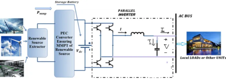
[image:2.595.324.539.406.603.2]Figure 2. Typical configuration of a single-phase low voltage micro-grid with distributed generation.
Figure 3. circuit diagram of a single phase full bridge inverter.
The state equations of the single phase inverter shown in Fig.3 are as follow:
𝐿𝑑𝑖𝐿
𝑑𝑡 +𝑉𝑜 =𝑉𝑖𝑛𝑣 (1)
𝑖𝐿=𝑖𝑐+𝑖𝑜 , 𝑖𝑐 =𝐶𝑑𝑉𝑑𝑡𝑜 (2) Where 𝑉𝑖𝑛𝑣 =𝑢𝑉𝐷𝐶 is the inverter output voltage and u is the controller’s input signal. Combining equations (1) and (2) results in:
d dt�
VO
ı̇L�=�
0 1C
−1L 0� � Vo
iL�+�
0
VDC
L �u +�− iO
C
0 � (3)
where inductive current (iL) and capacitor voltage (VO) are selected as state variables. VDC is the voltage of the DC link or UPS. iO and 𝑖𝑐 are the output current of the filter and the capacitor, respectively.
3. Controller Design, Stability Analysis
and Rotating Reference Signal
Algorithm
As the MG is supposed to be operating in islanded mode, we first design the voltage-frequency controller for one DG unit. Afterwards, we present the current controller and load sharing scheme based on the loads’ currents. In this study, loads’ currents are assumed to be measurable.
3.1. Sliding Mode Theory
Sliding mode control is a variable structure control method in which the controller output considering state variables of the system [28, 29]. Well known advantages of SMC are stability against load and line variations, robustness, good dynamic response and simple implementation [30-65]. The nth order model of the system which is considered by the sliding mode controller is as follows:
𝑥(𝑛)=𝑓(𝑥) +𝑔(𝑥)𝑢+𝛿(𝑥) (4) where 𝛿(𝑥) is system distortion. Distortion can be load variation and/or noises in the MG. The 𝑢 is control input, n
is the system order, and x is the system state vector. If the objective of the sliding mode controller is to force the system to track a reference signal, A sliding surface is defined based on the order of the system. In this paper, the system state equation is assumed to be first order or second order; consequently, these types of sliding surfaces are introduced in the following.
3.2. Sliding Surface of First Order System
Sliding surface is defined based on the error between output and reference signal as follows:
𝑆=𝑥 − 𝑥𝑟𝑒𝑓 (5)
where S and 𝑥𝑟𝑒𝑓 are the sliding surface and reference signal, respectively. The objective of the control method is to minimize the error to track the reference signal. As a result, the control equations are obtained by making the derivative of the sliding surface equal to zero:
𝑆̇= 0 → 𝑥̇ − 𝑥̇𝑟𝑒𝑓 =𝑓(𝑥) +𝑔(𝑥)𝑢+𝛿(𝑥)− 𝑥̇𝑟𝑒𝑓 = 0
→ 𝑢𝑒𝑞=𝑔−1(𝑥)[−𝑓(𝑥)− 𝛿(𝑥) +𝑥̇𝑟𝑒𝑓] (6)
3.3. Sliding Surface of Second Order System
𝑆=𝑥̇�+𝜆𝑥� (7) where 𝜆 is a positive number.
To derive the control equation, the derivative of the sliding surface is posed to zero:
𝑆̇= 0 → 𝑥̈ − 𝑥̈𝑟𝑒𝑓+𝜆𝑥̇�= 0
→ 𝑓(𝑥,𝑥̇) +𝑔(𝑥)𝑢+𝛿(𝑥)− 𝑥̈𝑟𝑒𝑓+𝜆𝑥̇�= 0
→ 𝑢𝑒𝑞=𝑔−1(𝑥)[−𝑓(𝑥,𝑥̇) +𝑥̈𝑟𝑒𝑓− 𝛿(𝑥)− 𝜆𝑥̇�] (8) Then, in order to boost the robustness of the controller against external distortions, a discrete part is also added to the control law as shown below:
𝑢=𝑢𝑒𝑞− 𝐾𝑠𝑖𝑔𝑛(𝑆) (9)
Where k is defined based on the corresponding Lyapunov function and sign represents the sign function. In order to validate stability of the proposed control law, a Lyapunov function should be defined; if the derivative of the Lyapunov is negative, the system stability is proved. In this case, the Lyapunov function and consequently its derivative are defined as follow:
𝑉(𝑥) = 0.5 𝑆2 → 𝑉̇(𝑥) =𝑆𝑆̇<−𝜂|𝑆| (10)
where 𝜂 is a constant positive number.
3.4. Rotating Reference Signal Algorithm
In this proposed sliding mode controller, the steady state error between desired voltage and output voltage is minimized by means of an adaptive rotating reference signal, . It will be shown later that the proposed rotating reference algorithm will reduce the THD and also will improve the voltage profile compared to the conventional SMC controllers with a constant reference signal. The proposed method improves the controller’s performance by adaptively adjusting varying the reference voltage of the controller. More precisely, the proposed method continuously updates the amplitude of the reference signal based on the voltage and current errors. The proposed algorithm can be formulated as follows:
𝑉𝑟𝑒𝑓 =𝑉𝑚sin (𝜔𝑡)
𝑧=𝑉𝑉𝑟𝑒𝑓
𝐿 ⎩ ⎪ ⎪ ⎨ ⎪ ⎪
⎧ 𝑧= 1 𝑖𝑓 𝑣𝐿= 0
z = 0.7 if 𝑣𝑣𝑟𝑒𝑓
𝐿 < 0.7
z = 1.3 if 𝑣𝑣𝑟𝑒𝑓
𝐿 > 1.3
z =𝑣𝑣𝑟𝑒𝑓
𝐿 if 0.7 <
𝑣𝑟𝑒𝑓
𝑣𝐿 < 1.3
𝑉𝑟𝑒𝑓_𝑛𝑒𝑤=𝑉𝑟𝑒𝑓∗ 𝑧 (11) Where 𝑉𝑟𝑒𝑓 is the sinusoidal reference signal and 𝑉𝐿 is the amplitude of the inverter output voltage signal. 𝑉𝑚 is the amplitude of reference signal that the output voltage of
inverter should tend to it. z is the Proportionality between output voltage and reference signal. The value of 𝑉𝑟𝑒𝑓_𝑛𝑒𝑤 is related to the z to force the error between 𝑉𝑟𝑒𝑓 and output voltage to tend to zero.
3.5. Voltage-frequency Controller
The goal of voltage-frequency control unit is to control the voltage-frequency by minimizing the voltage error:
ref
O
V
V
x
1=
−
(12)
ref C
ref
O V Ci dtd V
V dt d x dt d
x2 = 1 = ( − )= 1 −
(13) Where x2 is derivative of x1, and Vref is the reference signal defined as:
)
sin(
)
sin(
t
h
t
V
V
ref=
mω
=
newω
(14) where Vm and ω are denoted as amplitude and angular frequency, respectively. In this study, Vm is not considered to be constant; instead, its value is changing adaptively based on the algorithm explained by equation (11).
According to (12) and (13), the state-space equation (3) can be rewritten as follows:
+ + − = ) ( 0 LC 0 0 1 1 0 DC 2 1 2 1 t D u V x x LC x x dt d ref ref dtd V
V LC dt di C t
D()=−1 O− 1 − 22 (15)
As appears in (15) system state-space equation is second order; as a result, the switching surface can be defined as below:
2 1
*x x
S =λ + ,
λ
〉
0
(16)where
λ
is a positive real constant.Then the equivalent control energy should be retrieved. Thus, the sliding surface is derived and set to zero so that the equivalent control energy is calculated as follows:
)) ( 1 (
0 2 1
DC x LCx Dt V LC u S dt d
eq= − + −
→
= λ (17)
Finally, voltage control law is obtained as follow:
)
(S
sign
K
u
u
=
eq−
V∗
(18) To evaluate stability, the Lyapunov function given in (19) is examined:2
2
1
S
V
=
(19)η
η
DC
V
LC
K
SS
V
dt
d
V
〉
→
〈−
=
•(20)
Where
η
is maximum disturbance term of D(t) (|𝐷(𝑡)|≤ 𝜂).3.6. Current Controller
In this section, a sliding mode controller is designed to control the current of the rest two DG units; moreover, a pair of gains is defined for the two DG units which will be used to share the load current between them. Based on the output current and equation (2 and 3), the system state-space is first order. Accordingly, the model of the system is as indicated in (21):
d dtı̇o=−
1 LVo+
VDC
L u− 𝑑
𝑑𝑡𝑖𝑐 (21) So, the switching surface is defined as follow:
ref
o
i
i
S
=
−
(22) Then, the equivalent control energy must be retrieve. Thus, the sliding surface should be derived and set to zero so that equivalent control energy is calculated as:)
1
(
0
o CDC ref
eq
V
L
L
V
dt
d
i
dt
d
i
u
S
dt
d
=
→
=
+
+
(23)
Finally, the current controller is obtained as follows:
𝑢=𝑢𝑒𝑞− 𝐾𝑠∗ 𝑠𝑖𝑔𝑛(𝑆) (24) To keep stability, the Lyapunov function introduced in (19) is used to calculate boundaries of parameter Ks:
S DC S VL η
K 〉 (25)
where ηSis a positive constant.
Each one of the current controllers of DG units has a cap on power generation capacity, thus, the output current amplitude should be limited. Equation (26) shows the limitation on the reference current signal. It should be noted that a factor of the load current is used as the reference signal; when the reference signal peak violates the upper limit, the upper limit will be considered as the reference signal. This way the constraints of the system are taken into account. The proposed formulation is as below:
max )
3 )( 2 (
_
m
*
i
m
*
i
I
i
ref DG=
load
→
if load≤
max max
) 3 )( 2 (
_
i
i
I
m
*
i
I
i
if loadload load DG
ref
=
→
>
(26)Where Imax is the maximum current that can be produced by the inverter.
i
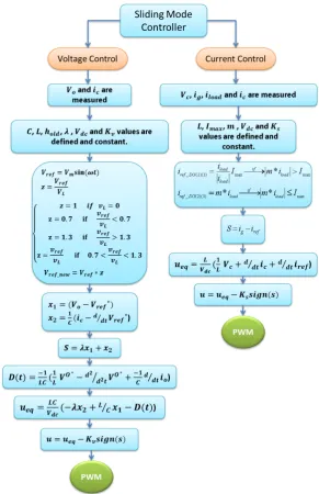
load is the load current and ‘m’ isFigure 4. . The flowchart of sliding mode controller.
4. Simulation Results
In this section, the performance of the algorithm is investigated under different load scenarios such as resistive, inductive and nonlinear loads. Fig.5 shows an islanded MG with three distributed generation units. Simulations are carried out by Matlab/Simulink software. Parameters of the electric power grid and control parameters are shown in table 1.
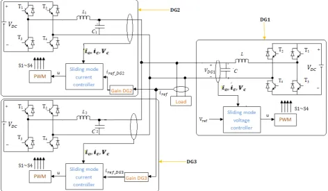
As shown in Fig.6, the nonlinear load consists of different elements such as resistor, capacitor and diodes. As shown in Fig.5, the parameters of system are measured, to be used as the input of the controller. For each DG, an appropriate controller shown in Fig.4 is chosen. According to Fig.5, DG1 is selected as the voltage-frequency control which is responsible for
regulating voltage-frequency of the micro-grid whenever the system faces any load variations. On the other hand, DG2 and
DG3 are controlled output current whose gains are used for sharing the load between them. The control signal is used as the
Figure 5. Simulated islanded micro-grid system which consists of three DG unit with the proposed controller.
Figure 6. Circuit diagram of simulated nonlinear load
Table 1. Parameters of the controller and the distributed generators
Symbol Quantity Value Generation UnitDistributed Symbol Quantity Value Distributed Generation Unit
DC
V DC voltage input 100V
Voltage-frequency controller unit
(DG1)
DC
V DC input voltage 100V
Current controller units (DG2
and DG3) r
ω Voltage angular frequency 314.16 L Filter inductive 11mH L Filter inductive 11 mH C Capacitor filter 220µF C Filter capacitor 220 µF KS Control parameters 0 .9
λ Control
parameters
15000 Imax Maximum production
current of each DG 15A
V
K 08.
f Switching
frequency 15kHZ
4.1. Case A: Performance under Resistive Load
Table 2. Resistive load parameters Initial load (ohm) Secondary load (ohm)
20 5
should be noted that 50 percent of load current is produced by DG2 while the remaining 50 percent is generated by DG3.
Fig.7 illustrates the simulation results.
Fig.7(a) and Fig.7(e) illustrate the micro-grid voltage and the zero steady state values of voltage, respectively. It can be simply inferred that the proposed algorithm is successfully able to track the reference signal with low error that implies robustness of the control framework against resistive load variations. The load current used as the reference current signal is depicted in Fig.7(b). Fig. 7(c) and 7(d) also show the reference signal and output current of DG2 and DG3, respectively. Fig. 7(c) and Fig. 7(d) also demonstrate the robustness of the proposed current controller against resistive load. It can simply be observed that, in the proposed algorithm, the rotating signal depends on the error between main reference signal and the output voltage signal. If the error between main reference signal and output voltage signal is increased, the proposed algorithm in turn increases the rotating reference signal to reduce the error.
(a)
(b)
(c)
(d)
[image:8.595.70.481.319.747.2](e)
Figure 7. Simulation results of the proposed controller with resistive load. a) Output voltage of the voltage-frequency controller unit (micro-grid voltage). b) Load current. c) Reference and generation current of DG2. d) Reference and generation current of DG3. e) zero steady state error of voltage.
4.2. Case B: Performance under Inductive Load
In this case, the performance of the sliding mode controller using rotating reference is investigated under inductive load. Parameters of the inductive load are described in table 3. At t=0.2 s, an inductive load is connected to the system. 50 percent of load current is generated by DG2 and the remaining 50 percent is generated
by DG3. Fig.8 illustrates the simulation results.
Table 3. Parameters of Inductive load Initial load (ohm) Secondary load
ohm mH
20 10 5
(a) Time (s)
0 0.05 0.1 0.15 0.2 0.25 0.3 0.35 0.4
Microgrid Voltage (V)
-60 -40 -20 0 20 40 60
Time (s)
0 0.05 0.1 0.15 0.2 0.25 0.3 0.35 0.4
Load Current (A)
-15 -10 -5 0 5 10 15
Time (s)
0 0.05 0.1 0.15 0.2 0.25 0.3 0.35 0.4
Output Current of DG2 (A)
-8 -6 -4 -2 0 2 4 6 8 10
Reference Signal Output current
Time (Sec)
0 0.05 0.1 0.15 0.2 0.25 0.3 0.35 0.4
Output Current of DG3 (A)
-8 -6 -4 -2 0 2 4 6 8 10
Reference Signal Output Current
Time (Sec)
0 0.05 0.1 0.15 0.2 0.25 0.3 0.35 0.4
Zero Steady State Error of Voltage
-20 -15 -10 -5 0 5 10 15 20
Time (Sec)
0 0.05 0.1 0.15 0.2 0.25 0.3 0.35 0.4
Microgrid Voltage (V)
(b)
(c)
(d)
(e)
Figure 8. Simulation results of the proposed controller under inductive load. a) Output voltage of the voltage-frequency controller unit (micro-grid voltage). b) Load current. c) Reference and generation current of DG2. d) Reference and generation current of DG3. e) Zero steady state error of voltage of phase c.
Fig.8 (a) shows the proposed MG voltage while Fig.8(e) illustrated the zero steady state of voltage which demonstrates that the proposed algorithm is able to track the reference signal with a low error. Robustness against connection of inductive load is shown as well. It should be noted that the phase angle difference observed between the voltage and the current does not have any negative effect on
the voltage-frequency controller. Load current used as the reference current signal is also shown in Fig.8(b). Fig.8(c) and 8(d) also illustrate the reference signal and output current of DG2 and DG3, respectively. As observed from
[image:9.595.61.298.81.611.2]Fig.8(c) and 8(d), at t=0.2 s, an inductive load is connected to the system; robustness of the proposed current controller against inductive load connection and phase angle variation between current and voltage signal are demonstrated. 4.3. Case C: Performance under Nonlinear Load
Table 4. Parameters of nonlinear load
Initial load (ohm)
Secondary load ohm
𝑅𝑑𝑐 𝑅𝑠 𝐶𝑑𝑐
20 18 2 8200
In this case, performance of the sliding mode controller with rotating reference is explored under nonlinear load. Parameters of the nonlinear load are tabulated in Table.4. At t=0.2 s, an nonlinear load is connected to the system. It should be addressed that 60 percent of load current is generated by DG2 while the remaining 40 percent is
generated by DG3. Fig. 9 illustrates the simulation results.
(a)
(b)
(c) Time (Sec)
0 0.05 0.1 0.15 0.2 0.25 0.3 0.35 0.4
Load Current (A)
-8 -6 -4 -2 0 2 4 6 8
Time (Sec)
0 0.05 0.1 0.15 0.2 0.25 0.3 0.35 0.4
Output Current of DG2 (A)
-4 -2 0 2 4 6
Reference Signal Output Current
Time (Sec)
0 0.05 0.1 0.15 0.2 0.25 0.3 0.35 0.4
Output Current of DG3 (A)
-4 -2 0 2 4 6
Reference Signal Output Current
Time (Sec)
0 0.05 0.1 0.15 0.2 0.25 0.3 0.35 0.4
Zero Steady Error of Voltage
-10 -5 0 5 10
F
µ
Time (Sec)
0 0.05 0.1 0.15 0.2 0.25 0.3 0.35 0.4
Microgrid Voltage (V)
-80 -60 -40 -20 0 20 40 60 80
Time (Sec)
0 0.05 0.1 0.15 0.2 0.25 0.3 0.35 0.4
Load Current (A)
-30 -20 -10 0 10 20 30
Time (Sec)
0 0.05 0.1 0.15 0.2 0.25 0.3 0.35 0.4
Output Current of DG2 (A)
-15 -10 -5 0 5 10 15 20
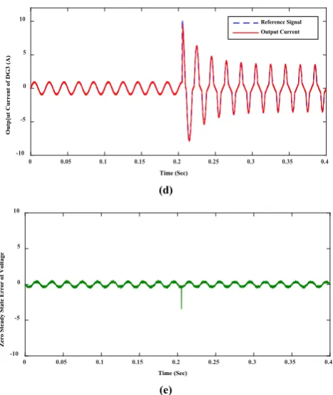
[image:9.595.311.553.200.265.2] [image:9.595.315.548.355.753.2](d)
[image:10.595.61.295.77.355.2](e)
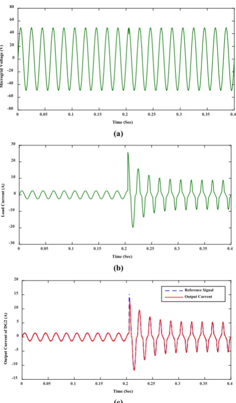
Figure 9. simulation results of proposed controller under nonlinear load. a) Output voltage of the voltage-frequency controller unit (micro-grid voltage). b) Load current. c) Reference and generation current of DG2. d) Reference and generation current of DG3. e) Zero steady state error of voltage of phase c.
Fig. 9(a) demonstrates the proposed MG voltage while Fig.9(e) shows the zero steady state error of voltage of phase c. Fig.9(a) and 9(e) demonstrate that the proposed algorithm is able to track the reference signal with a low error. Robustness of the algorithm against nonlinear load variation and other parallel DG units is also demonstrated. At t=0.2 s, a nonlinear load is connected to the system which causes voltage drop. The proposed controller has a fast response and decrease the steady state error of output voltage to zero. Load current used as the reference current signal is shown in Fig.9(b). Fig.9(c) and 9(d) show the reference signal and output current of DG2 and DG3, respectively. Robustness of
the proposed current controller against nonlinear load is also shown in Fig.9(c) and (d). Fig.9(c) and (d) also show that the controller is able to track the reference current signal. At t=0.2 s, a nonlinear load is connected to the system, the error is increased, so the rotating reference signal is changed to decrease the error faster.
In part ‘a’ of Fig.7, 8 and 9, it is shown that the proposed method is able to provide stable voltage for the MG. Moreover, the proposed method is robust against disturbances caused by different load types under different load connection. The zero steady state error between reference signal and MG’s voltage in different load connections (such as resistive, inductive and nonlinear load) is shown in part ‘e’ of Fig.7, 8 and 9, respectively. Part ‘e’ of the above-mentioned figures demonstrate that the proposed controller is able to provide a desirable performance in tracking the reference voltage signal. Moreover, it can be observed that the controller is able to demonstrate a suitable response to load variations. Finally, the proposed method can successfully regulate the output voltage waveform to the reference voltage waveform.
Part ‘b’ and ‘c’ of Fig.7, 8 and 9 demonstrate the reference current and generation current of DG2 and DG3 while facing
resistive, inductive and nonlinear load connections, respectively. It can be observed that the controller is able to provide a good performance in tracking reference signal, and the load sharing between each DG unit is carried out by defining a gain to share the load current. Moreover, it is shown that loads variations and phase angle variations do not have negative effects on the controller’s performance and also the controller has a fast response.
[image:10.595.64.548.596.717.2]Performance of the proposed sliding mode controller with rotating reference is compared with that of classic sliding mode controller is mentioned in Table 5. For the sake of fair and through comparison, different values for
λ
(such as 8000 and 15000) are considered. It can be inferred that the proposed algorithm is able to provide improved output peak voltage and total harmonic distortion as well as reduced steady state error.Table 5. steady state results of output voltage of phase a.
5th
Harmonic 4th
Harmonic 3th
Harmonic 2th
Harmonic THD(%)
Output Voltage RMS Output
Voltage Peak Controller
0.33% 0.00%
0.36% 0.01%
0.58% 34.92
49.39
Sliding Mode Controller with Rotating Reference 15000
0.35% 0.01%
0.39% 0.01%
0.62% 34.02
48.12
Classic Sliding Mode Controller
0.39% 0.07%
0.45% 0.06%
0.78% 34.75
49.15
Sliding Mode Controller with Rotating Reference 8000
0.42% 0.85%
0.7% 1.07%
1.88% 33.8
47.18
Classic Sliding Mode Controller
Time (Sec)
0 0.05 0.1 0.15 0.2 0.25 0.3 0.35 0.4
Outp[ut Current of DG3 (A)
-10 -5 0 5
10 Reference Signal
Output Current
Time (Sec)
0 0.05 0.1 0.15 0.2 0.25 0.3 0.35 0.4
Zero Steady State Error of Voltage
-10 -5 0 5 10
5. Conclusions
In this paper, a novel sliding mode controller with adaptive rotating reference is proposed to control an islanded micro-grid. The micro-grid consists of three low voltage distributed generation and different types of load such as resistive, inductive and nonlinear load. It is assumed that the load current is measurable and used as the reference current signal for controlling DGs. It is shown that the proposed controller is able to track reference signal with a low steady state error. Moreover, using the proposed rotating reference signal has shown to be able to improve the steady state results of the controller, such as output voltage peak, RMS and THD. Simulations results also indicate that the proposed controller is robust against different load connections. The proposed controller scheme is simple and can be easily implemented on the FPGA/DSP board for implementing the controller.
REFERENCES
[1] Hamzeh, Mohsen, Houshang Karimi, and Hossein Mokhtari. "Harmonic and Negative-Sequence Current Control in an Islanded Multi-Bus MV Microgrid." Smart Grid, IEEE Transactions on 5, no. 1 (2014): 167-176.
[2] Turner, Greg, Jay P. Kelley, Caroline L. Storm, D. A. Wetz, and W-J. Lee. "Design and Active Control of a Microgrid Testbed." IEEE Transactions on Smart Grid, 2015; 6(1): 73 – 81.
[3] Xu, Yinliang, Wei Zhang, Gabriela Hug, Soummya Kar, and Zhicheng Li. "Cooperative Control of Distributed Energy Storage Systems in a Microgrid." IEEE Transactions on Smart Grid, 2015; 6(1): 238 – 248.
[4] Su, Xiaoling, Minxiao Han, Josep M. Guerrero, and Hai Sun. "Microgrid Stability Controller Based on Adaptive Robust Total SMC." Energies 8, no. 3 (2015): 1784-1801.
[5] Abdel-Rahim, Naser M., and John E. Quaicoe. "Analysis and design of a multiple feedback loop control strategy for single-phase voltage-source UPS inverters." Power Electronics, IEEE Transactions on 11, no. 4 (1996): 532-541. [6] Kukrer, Osman, Hasan Komurcugil, and Alper Doganalp. "A three-level hysteresis function approach to the sliding-mode control of single-phase UPS inverters." Industrial Electronics, IEEE Transactions on 56, no. 9 (2009): 3477-3486.
[7] Tzou, Ying-Yu, S-L. Jung, and Hsin-Chung Yeh. "Adaptive repetitive control of PWM inverters for very low THD AC-voltage regulation with unknown loads." Power Electronics, IEEE Transactions on 14, no. 5 (1999): 973-981. [8] Moharana, Akshaya, and P. K. Dash. "Input-output linearization and robust sliding-mode controller for the VSC-HVDC transmission link." Power Delivery, IEEE Transactions on 25, no. 3 (2010): 1952-1961.
[9] Niknam, Taher, and Mohammad Hassan Khooban. "Fuzzy sliding mode control scheme for a class of non-linear uncertain chaotic systems." IET Science, Measurement &
Technology 7, no. 5 (2013): 249-255.
[10]Alfi, Alireza, Ali Akbarzadeh Kalat, and Mohammad Hassan Khooban. "Adaptive fuzzy sliding mode control for synchronization of uncertain non-identical chaotic systems using bacterial foraging optimization." Journal of Intelligent and Fuzzy Systems 26, no. 5 (2014): 2567-2576.
[11]Soltanpour, Mohammad Reza, Pooria Otadolajam, and Mohammad Hassan Khooban. "Robust control strategy for electrically driven robot manipulators: adaptive fuzzy sliding mode." IET Science, Measurement & Technology (2014). [12]Niknam, Taher, Mohammad Hassan Khooban, Abdollah
Kavousifard, and Mohammad Reza Soltanpour. "An optimal type II fuzzy sliding mode control design for a class of nonlinear systems." Nonlinear Dynamics 75, no. 1-2 (2014): 73-83.
[13]Kordkheili, R. Ahmadi, and M. Mehrasa. "Sliding mode control for three-phase AC/DC voltage-source Boost converter." In Power Electronics Electrical Drives Automation and Motion (SPEEDAM), 2010 International Symposium on, pp. 1213-1217. IEEE, 2010.
[14]Wai, Rong-Jong, Chih-Ying Lin, Yu-Chih Huang, and Yung-Ruei Chang. "Design of high-performance stand-alone and grid-connected inverter for distributed generation applications." Industrial Electronics, IEEE Transactions on 60, no. 4 (2013): 1542-1555.
[15]Silva, J. Fernando. "Sliding-mode control of boost-type unity-power-factor PWM rectifiers." Industrial Electronics, IEEE Transactions on 46, no. 3 (1999): 594-603.
[16]Wai, Rong-Jong, and Chun-Yu Lin. "Active low-frequency ripple control for clean-energy power-conditioning mechanism." Industrial Electronics, IEEE Transactions on 57, no. 11 (2010): 3780-3792.
[17]Babazadeh, Maryam, and Houshang Karimi. "A robust two-degree-of-freedom control strategy for an islanded microgrid." Power Delivery, IEEE Transactions on 28, no. 3 (2013): 1339-1347.
[18]Hamzeh, Mohsen, Houshang Karimi, and Hossein Mokhtari. "A new control strategy for a multi-bus MV microgrid under unbalanced conditions." Power Systems, IEEE Transactions on 27, no. 4 (2012): 2225-2232.
[19]Nikkhajoei, Hassan, and Robert H. Lasseter. "Distributed generation interface to the CERTS microgrid." Power Delivery, IEEE Transactions on 24, no. 3 (2009): 1598-1608. [20]Hatziargyriou, Nikos, Hiroshi Asano, Reza Iravani, and Chris Marnay. "Microgrids." Power and Energy Magazine, IEEE 5, no. 4 (2007): 78-94.
[21]Guerrero, Josep M., L. Garcia de Vicuna, José Matas, Miguel Castilla, and Jaume Miret. "Output impedance design of parallel-connected UPS inverters with wireless load-sharing control." Industrial Electronics, IEEE Transactions on 52, no. 4 (2005): 1126-1135.
[22]Guerrero, Josep M., José Matas, Luís García De Vicuña, Miguel Castilla, and Jaume Miret. "Wireless-control strategy for parallel operation of distributed-generation inverters." Industrial Electronics, IEEE Transactions on 53, no. 5 (2006): 1461-1470.
system for robust microgrid operation and seamless mode transfer in active distribution systems." Smart Grid, IEEE Transactions on 2, no. 2 (2011): 352-362.
[24]Vandoorn, Tine L., Bart Meersman, Jeroen DM De Kooning, and Lieven Vandevelde. "Analogy between conventional grid control and islanded microgrid control based on a global DC-link voltage droop." Power Delivery, IEEE Transactions on 27, no. 3 (2012): 1405-1414.
[25]Karimi, Houshang, Edward J. Davison, and Reza Iravani. "Multivariable servomechanism controller for autonomous operation of a distributed generation unit: Design and performance evaluation." Power Systems, IEEE Transactions on 25, no. 2 (2010): 853-865.
[26]Delghavi, Mohammad B., and Amirnaser Yazdani.
"Islanded-mode control of electronically coupled distributed-resource units under unbalanced and nonlinear load conditions." Power Delivery, IEEE Transactions on 26, no. 2 (2011): 661-673.
[27]Dasgupta, Souvik, Sanjib Kumar Sahoo, and Sanjib Kumar Panda. "Single-phase inverter control techniques for interfacing renewable energy sources with microgrid—Part I: Parallel-connected inverter topology with active and reactive power flow control along with grid current shaping." Power Electronics, IEEE Transactions on 26, no. 3 (2011): 717-731. [28]Slotine, Jean-Jacques E., and Weiping Li. Applied nonlinear control. Vol. 60. Englewood Cliffs, NJ: Prentice-Hall, 1991. [29]Khalil, Hassan K., and J. W. Grizzle. Nonlinear systems. Vol.
3. New Jersey: Prentice hall, 1996.
[30]Khooban MH, Niknam T, Blaabjerg F, Dragičević T. A new load frequency control strategy for micro-grids with considering electrical vehicles. Electric Power Systems Research. 2016 Nov 9.
[31]Khooban MH, Vafamand N, Liaghat A, Dragicevic T. An optimal general type-2 fuzzy controller for Urban Traffic Network. ISA transactions. 2016 Nov 3.
[32]Khooban MH, Vafamand N, Dragicevic T, Blaabjerg F, Niknam T. Model Predictive Control based on TS Fuzzy model For Electrical Vehicles Delayed Model. IET Electric Power Applications. 2016 Oct 27.
[33]Khooban MH, Niknam T, Blaabjerg F, Dehghani M. Free chattering hybrid sliding mode control for a class of non-linear systems: electric vehicles as a case study. IET Science, Measurement & Technology. 2016 Oct 1; 10(7):776-85. [34]Naghavi SV, Naghavi SV, Safavi AA, Safavi AA, Khooban
MH, Khooban MH, Pourdehi S, Pourdehi S, Ghaffari V, Ghaffari V. A robust control strategy for a class of distributed network with transmission delays: LMI-based model predictive controller. COMPEL-The international journal for computation and mathematics in electrical and electronic engineering. 2016 Sep 5; 35(5):1786-813.
[35]Azami A, Naghavi SV, Tehrani RD, Khooban MH,
Shabaninia F. State estimation strategy for fractional order systems with noises and multiple time delayed measurements. IET Science, Measurement & Technology. 2016 Aug 19. [36]Khooban MH, Niknam T, Blaabjerg F, Davari P, Dragicevic T.
A robust adaptive load frequency control for micro-grids. ISA transactions. 2016 Jul 28.
[37]Naghash-Almasi O, Khooban MH. PI adaptive LS-SVR control scheme with disturbance rejection for a class of uncertain nonlinear systems. Engineering Applications of Artificial Intelligence. 2016 Jun 30; 52: 135-44.
[38]Dehghani M, Khooban MH, Niknam T. Fast fault detection and classification based on a combination of wavelet singular entropy theory and fuzzy logic in distribution lines in the presence of distributed generations. International Journal of Electrical Power & Energy Systems. 2016 Jun 30; 78: 455-62. [39]Rahimi A, Bavafa F, Aghababaei S, Khooban MH, Naghavi SV. The online parameter identification of chaotic behaviour in permanent magnet synchronous motor by Self-Adaptive Learning Bat-inspired algorithm. International Journal of Electrical Power & Energy Systems. 2016 Jun 30; 78: 285-91. [40]Modirkhazeni A, Almasi ON, Khooban MH. Improved
frequency dynamic in isolated hybrid power system using an intelligent method. International Journal of Electrical Power & Energy Systems. 2016 Jun 30; 78: 225-38.
[41]Sadeghi MS, Vafamand N, Khooban MH. LMI-based Stability Analysis and Robust Controller Design for a Class of Nonlinear Chaotic Power Systems. Journal of the Franklin Institute. 2016 Jun 2.
[42]Heydari-doostabad H, Khalghani MR, Khooban MH. A novel control system design to improve LVRT capability of fixed speed wind turbines using STATCOM in presence of voltage fault. International Journal of Electrical Power & Energy Systems. 2016 May 31; 77: 280-6.
[43]Khooban MH, Vafamand N, Niknam T. T–S fuzzy model predictive speed control of electrical vehicles. ISA transactions. 2016 May 7.
[44]Khooban MH, Niknam T, Sha-Sadeghi M. Speed control of electrical vehicles: a time-varying proportional–integral controller-based type-2 fuzzy logic. IET Science, Measurement & Technology. 2016 May 1; 10(3):185-92. [45]Soltanpour MR, Khooban MH, Niknam T. A robust and new
simple control strategy for a class of nonlinear power systems: induction and servomotors. Journal of Vibration and Control. 2016 Apr 1; 22(6):1568-92.
[46]Mahboubi-Moghaddam E, Narimani MR, Khooban MH, Azizivahed A. Multi-objective distribution feeder reconfiguration to improve transient stability, and minimize power loss and operation cost using an enhanced evolutionary algorithm at the presence of distributed generations. International Journal of Electrical Power & Energy Systems. 2016 Mar 31; 76: 35-43.
[47]Khooban MH, Siahi M, Soltanpour MR. Robust and simple intelligent observer-based fault estimation and reconstruction for a class of non-linear systems: HIRM aircraft. The Aeronautical Journal. 2016 Mar 1;120(1225):457-72.
[48]Khooban MH, Naghash-Almasi O, Niknam T, Sha-Sadeghi M. Intelligent robust PI adaptive control strategy for speed control of EV (s). IET Science, Measurement & Technology. 2016 Feb 29.
[50]Rafiei M, Niknam T, Khooban MH. Probabilistic electricity price forecasting by improved clonal selection algorithm and wavelet preprocessing. Neural Computing and Applications. 2016:1-3.
[51]Khooban MH, Niknam T, Sha-Sadeghi M. A time-varying general type-II fuzzy sliding mode controller for a class of nonlinear power systems. Journal of Intelligent & Fuzzy Systems. 2016 Jan 1(Preprint):1-1.
[52]Soltanpour MR, Khooban MH, Khalghani MR. An optimal and intelligent control strategy for a class of nonlinear systems: adaptive fuzzy sliding mode. Journal of Vibration and Control. 2016; 22(1):159-75.
[53]Veysi M, Soltanpour MR, Khooban MH. A novel
self-adaptive modified bat fuzzy sliding mode control of robot manipulator in presence of uncertainties in task space. Robotica. 2015 Dec 1;33(10):2045-64.
[54]Khooban MH, Niknam T. A new intelligent online fuzzy tuning approach for multi-area load frequency control: Self Adaptive Modified Bat Algorithm. International Journal of Electrical Power & Energy Systems. 2015 Oct 31; 71: 254-61. [55]Bavafa F, Rahimi A, Khooban MH. A simple and intelligent online parameter identification of nonlinear chaotic systems. Journal of Intelligent & Fuzzy Systems. 2015 Oct 23; 29(4):1501-9.
[56]Khooban MH, Niknam T. A new and robust control strategy for a class of nonlinear power systems: Adaptive general type-II fuzzy. Proceedings of the Institution of Mechanical Engineers, Part I: Journal of Systems and Control Engineering. 2015 Mar 24:0959651815571621.
[57]Abadi DN, Khooban MH. Design of optimal Mamdani-type fuzzy controller for nonholonomic wheeled mobile robots. Journal of King Saud University-Engineering Sciences. 2015 Jan 31;27(1):92-100.
[58]Khalghani MR, Khooban MH. A novel self-tuning control method based on regulated bi-objective emotional learning controller's structure with TLBO algorithm to control DVR compensator. Applied Soft Computing. 2014 Nov 30; 24: 912-22.
[59]Soltanpour MR, Otadolajam P, Khooban MH. Robust control strategy for electrically driven robot manipulators: adaptive fuzzy sliding mode. IET Science, Measurement & Technology. 2014 Sep 2; 9(3):322-34.
[60]Khalghani MR, Shamsi-nejad MA, Khooban MH. Dynamic voltage restorer control using bi-objective optimisation to improve power quality's indices. IET Science, Measurement & Technology. 2014 Jul; 8(4):203-13.
[61]Ghaemi M, Hosseini-Sani SK, Khooban MH. Direct adaptive general type-2 fuzzy control for a class of uncertain non-linear systems. IET Science, Measurement & Technology. 2014 Apr 15; 8(6):518-27.
[62]Khooban MH, Nazari Maryam Abadi D, Alfi A, Siahi M. Optimal Type-2 fuzzy controller for HVAC systems. AUTOMATIKA: časopis za automatiku, mjerenje, elektroniku, računarstvo i komunikacije. 2014 Feb 27; 55(1):69-78.
[63]Shahsadeghi M, Khooban MH, Niknam T. A robust and simple optimal type II fuzzy sliding mode control strategy for a class of nonlinear chaotic systems. Journal of Intelligent & Fuzzy Systems. 2014 Jan 1; 27(4):1849-59.
[64]Alfi A, Kalat AA, Khooban MH. Adaptive fuzzy sliding mode control for synchronization of uncertain non-identical chaotic systems using bacterial foraging optimization. Journal of Intelligent & Fuzzy Systems. 2014 Jan 1; 26(5):2567-76.
[65]Shamsi-Nejad M, Khalghani MR, Khooban MH.