Journal of Chemical and Pharmaceutical Research, 2014, 6(6):1454-1459
Research Article
CODEN(USA) : JCPRC5
ISSN : 0975-7384
Study on the precise detection method of pavement structure depth
Lin Guo-Qing and Wang Jian-Feng
School of Automobile, Chang’an University, Xi’an, China
_____________________________________________________________________________________________
ABSTRACT
Structural depth of pavement is a key indicator to reflect pavement macroscopic structure. A measurement method using laser-displacement-sensors is presented. Based on this method, an improved least square method is used to remove the trend of pavement, and then the structure depth of pavement can be calculated. A detection system including hardware and software is developed, which can achieve accurate and rapid measurement in applications. Reliability and performance of the developed system were tested in some experiments. The results show that the presented method can measure the structure depth of pavement accurately and rapidly.
Key words: Traffic engineering; Structural depth; Laser; displacement sensor.
_____________________________________________________________________________________________
INTRODUCTION
Anti-sliding performance of road is directly related to traffic safety. And pavement macro-structure affects anti-sliding performance directly. It also affects drainage ability of pavement in rainy days. Good road macro-structure can promptly remove surface water, prevent pavement water film and improve driving safety factor [1, 2]in rainy days. Pavement structural depth is an important indicator of Pavement macro-structure. So how to use better method, with low cost to obtain the high accuracy of pavement structural depth indicators become the difficulty and key factor in road detection area.
Pavement structural depth detection methods used at home and abroad are mainly sand method, drainage method, digital image analysis method and laser profile measurement method. Each of the methods mentioned above has their own advantages and disadvantages. Sand method is to pave known volume of standard sand in the testing pavement, then use rubber sheet which is at the bottom of the push plate to push the sand into a round flat. The volume ratio of sand and the mean area of paving round is the depth of pavement structure. Designed by the British Institute of Roads, this method is characterized by convenient operation. But prolonged detection will give operator high labor intensity, poor security, also it is not available in wet weather. Drainage method is accomplished by monitoring the excluding time of fixed volume water through the pavement to reflect the macro structure of pavement indirectly, this method is designed by the French, because of its complicated measuring operation , the current application is small. Digital image analysis method is carried out by digital analysis of pavement texture picture, then calculated the pavement structure depth with the information such as the Gray-scale image, simple is the biggest feature of this method, but the measurement repeatability is not well, and it does not have a strong correlation with sand method, so there is no use in practical engineering test [3].
vehicle during the collection process. Due to the influence of vibration testing vehicle itself and the pavement trend, the collected elevation information does not only include the texture information of pavement, but also the trend information of the pavement. However, the pavement structure depth is merely related to the texture information, only to get precise pavement texture can we calculate the pavement structural depth index accurately. So how to get the real pavement texture information becomes the difficulty of the Laser detection section method.
This paper mainly studies the accurate detection principle of pavement structure depth, develops pavement structure depth detection system which can be used in engineering practice with high-speed and high-accuracy.
1 DETECTION PRINCIPLE
In china, sand method is considered as the standard test method for highway pavement structural depth measurement. In order to judge if the outcome meets the requirements of the anti sliding performance of pavement, the pavement structural depth results that all methods obtained must be transformed into sand method’s pavement structural depth. Evaluation index of pavement structural depth is mean tectonic depth (MTD).
1.1 TRADITIONAL DETECTION PRINCIPLE
The principle of laser profiler used to detect pavement structure depth is to use laser sensor which is mounted on the inspection vehicle to project line laser beam in order to obtain the pavement section curved outlines according to the reflected light accepted. Then the pavement section curved outlines are divided into 100mm long segment curve; the mean segment depth(MSD) of each fragment curve are calculated; the mean of all fragments curve of MSD are taken as the pavement mean profile depth(MPD);and MPD translated into the MTD[4]through the relevant equation. The calculation principle of each fragment curve of MSD is shown in Figure 1; the calculation method is as follows:
First, calculating the average of elevation values of all points on the curve; secondly, dividing the segment curve into two sections evenly. Thirdly, Calculating the elevation valuesmax1andmax2on the highest point of each curve, and then calculating the difference between elevation values of the two highest point and the whole height average of the fragment curve. The arithmetic average of these two differences is the mean segment depth of the fragment curve.
[( 1 ) ( 2 )] / 2 ( 1 2) / 2
[image:2.595.175.430.419.561.2]MSD= max −ave + max −ave = max +max −ave (1)
Figure 1. The counting principle of MSD
1.2 IMPROVED DETECTION PRINCIPLE OF TEXTURE DEPTH
The calculated unit mentioned above is based on the cross-sectional of testing car. Due to the high cost of line laser detection, complex detection system structure and the improper trend such as cross slope added in the cross section, pavement MPD measured by this method must be related before they can get MTD, it can not obtain pavement MTD directly.
Aiming at the shortage of the current detection method, this paper presents an improved pavement structural depth detection method, the results of which do not need to relate, and the pavement MTD can be obtained directly.
method to count, the detection result is not necessarily reliable. So in order to get accurate test result of the pavement structural depth, the difficulty is how to remove this complex trend from the test curve.
In traditional least method, to get rid of the trend is by using least squares [6-10] to linear fitting the data sampling within the given sampling length, assuming the sampling points is N within the length of the curve, the data sequence isx=
{
x(1), (2),... ( )x x N}
, the data is divided into m same length section with N sampling points, then thedata sequence in the section m isxm=
{
x m n( * +1), (x m n* +2),... (x m n* +n)}
, the least squares linear equation of the msegment of is:
^
m m m
x =a i+b
(2)
^ 2
( m m) min
i
x −x =
∑
(3)
Among this:i=
{
m n* +1,m n* +2,... *m n+n}
,According to equation (2) and (3), the obtained trend line is broken line and the boundaries of each segment are discontinuous. In order to obtain a reasonable curve trend, this paper proposes an improved least square method to get rid of this trend, specific methods are as follows:
In the evaluated fragment curve length (100mm), there are N data points, dividing any continuous length data segment of n into several section, taking this section as the analysis base section, then taking sample from the K data points, k=1, 2,...N− +n 1, the line which using least square method to obtain from the point k is:
( ) ^
( ) ( )
k
k k
x =a i+b (4)
Among this:i=
{
k k, +1,...,k+ −n 1}
This method can get N-n+1 least squares line throughout the analysis segment. These lines increased gradually with the value of k, and sliding the whole fragment along the segment curve. To the k data, T k( )curve can be obtained to describe the tendency position of this segment, taking the average of the K fitting line in this point as the trend location of this position. The curve trend position of the k data points can be expressed as:
( ) ^
^
1 ( ) ^
1
1/ ( ) ( ),1
( )
1/ ( ) ( ),
T k i i k n T k
i i k n
T k x k k n
x k
T k x k n k N
= − + = − + ≤ ≤ = ≤ ≤
∑
∑
(5) Among this: ,1( ) , 1
1, 1
k k n
T k n n k N n
N k N n k N
≤ ≤ = ≤ ≤ − + − + − + ≤ ≤
Taking the trend curves calculated by formula (5) as a baseline, this baseline value is a smooth curve. It can reflect the change of trend surface precisely and continuously, remove the trend of the date within the analysis fragment and then calculate the curve of pavement structure depth according to the introduction method of formula (1).
Figure 2. The result of traditional methods
Figure 3. The result of improved methods
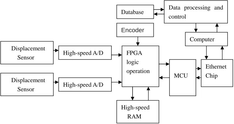
2 THE DESIGN OF THE SYSTEM STRUCTURE AND SOFTWARE
The structure of detection system is shown in Figure 4. The hardware system includes a laser displacement sensor, distance sensor (encoder), data acquisition card, computer and power etc. Software uses Windows system as their operating platform chooses Microsoft's SQL Server 2000 as the database management system to manage and maintain the test results, Visual Studio 2010.NET as the development environment and object-oriented programming language C + + for development. The software system adopts three layer structures which include user client, application server and database server, where the user client provides user operation interface, the application server encapsulates the business logic rules of pavement structural depth detection and the database server saves the testing results of structural depth.
High-speed RAM
Ethernet Chip MCU
Computer Data processing and control
FPGA logic operation Database
Encoder
High-speed A/D
Displacement Sensor Displacement
Sensor
[image:4.595.107.506.526.739.2]The system uses a distance sensor (encoder) to provide a trigger signal to let the two laser displacement sensor is mounted on the left and right wheels of the testing vehicle sample synchronously. Encoder is mounted on the vehicle's wheels. When the testing vehicle travels on the detected road, with the rotation of the wheel, the encoder will output a square wave signal whose frequency is changing with the speed. This signal provides a trigger signal for the two laser displacement sensors; system adopts CPLD (Complex Programmable Logic Device) to achieve the driver and logic operation of the laser displacement sensor.
3 FIELD TEST
3.1 CALIBRATION TESTS
In order to verify the accuracy of the system, standard height gauge is used to calibrate the detection system, the specific method is to place a highly known gauge in the actual road surface every 10 meters, the placed order is shown in Table 1. Then the detection system is used to detect the height of the quality block. The test results and error are shown in table 1.
3.2 COMPARISON TESTING
Due to the difference of actual amount of block and road construction have and the common methods that pavement structure depth usually use is sand method, so making a comparison test between the detection system and sand method. Specific methods are:
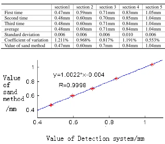
Five different typical pavements are selected which have different texture depth. Each section is 100 meters. Then detecting each road section for three times; the average detection value of the 100 meters is in table 2.
[image:5.595.234.380.388.468.2]Table 1 show that the detection system used in this study has good detection accuracy, and the maximum detection error is 0.019mm.The correlation which is established between the detection systems and sand method is shown in table 2
Table 1 .the calibration result of detection system
Gauge block (mm) test(mm) error
14 14.019 0.019
12 12.009 0.009
10 10.001 0.001
8 8.001 0.001
6 5.998 -0.002
4 3.999 -0.001
2 2.001 0.001
[image:5.595.163.446.488.735.2]
Table 2 .comparison results between detection system and sand method
section1 section 2 section 3 section 4 section 5
First time 0.47mm 0.59mm 0.71mm 0.83mm 1.05mm
Second time 0.48mm 0.60mm 0.70mm 0.85mm 1.04mm
Third time 0.48mm 0.60mm 0.71mm 0.84mm 1.04mm
average 0.48mm 0.60mm 0.71mm 0.84mm 1.04mm
Standard deviation 0.006 0.006 0.006 0.010 0.006
Coefficient of variation 1.211% 0.968% 0.817% 1.191% 0.553%
Value of sand method 0.47mm 0.60mm 0.7mm 0.84mm 1.04mm
As can be seen from Figure 5, the results between sand depth detection method and the proposed pavement structure depth detection method in this paper have a high correlation. Due to removal of the pavement trend item, the detection structure depth does not need to do any related process and can be used directly. Pavement structural depth of laser detection system developed by this method is used to do detection in some section of motorway such as: An yang – He bi, Wu Wei – Gu Lang, San Men Xia - Guan Yin Miao hall. Through the comparison of the test results between the developed detection system and the sand method, the maximum detection error of the detection system of pavement structural depth is less than 2%.
CONCLUSION
In order to get rid of the error such as behind detection methods, big detection difficulty, high cost and low accuracy, we proposed a new detection pavement structure depth method. Specific method is to use laser displacement sensor to detect the road surface elevation information in high-density, adopt the improved least square method proposed to remove the pavement tendency of pavement elevation information and obtain accurate information. Finally,using
the texture information of the road surface to calculate the pavement structure depth. In accordance with the proposed detection method, we developed detection system and detection software, making the detection of pavement structure depth more accurate and rapid. The calibration experiments and field tests shows that by using this automatic detection system of pavement structure depth, continuous detection in various vehicle speeds can be achieved. The test results have high correlation with the sand method and can be used directly.
Acknowledgments
The authors gratefully acknowledge the Fundamental Research Funds for the Central Universities of China for contract 2014G1221018, under which the present work was possible.
REFERENCES
[1]J He,X Liu,YK Chen,et al, Journal of traffic and Transportation Engineering,2009,11(1), 58-63. [2]X Dong, SP Zhang, XQ Ding, et al, Highway, 2011, 11, 14-20.
[3] BT Huang, WP Tian, JC Li, et al, China Journal of highway and transport,2008,21(4),12-17.
[4]FR Zhao, JH Gong, YY Chang, Journal of traffic and Transportation Engineering, 2012, 12(4), 17-24. [5]P Cao, XP Yan, XQ Bai, Tribology, 2009, 29(4), 306-310.
[6]P Wu, Journal of Chemical and Pharmaceutical Research, 2014, 6(2), 38-46.
[7] B, Wang, YL Zhao, Journal of Chemical and Pharmaceutical Research, 2013, 5(12), 21-26.