POWER FACTOR IMPROVEMENT IN POWER SYSTEM WITH THE INTEGRATION OF RENEWABLE ENERGY
MOHD AIDIL BIN ARDI
A project report is submitted in partial Fulfillment of the requirements for the award of the
Degree of Master of Electrical Engineering
Faculty of Electrical and Electronic Engineering University Tun Hussein Onn Malaysia
ABSTRACT
ABSTRAK
CONTENTS
TITLE i
DECLARATION ii
DEDICATION iii
ACKNOWLEDGEMENTS iv
ABSTRACT v
CONTENTS vii
LIST OF TABLES xiv
CHAPTER 1 INTRODUCTION 1
1.1 Introduction 1
1.2 Problem Statement 2
1.3 Research Hypothesis 3
1.4 Project Objectives 3
1.5 Project Scopes 4
1.6 Report Outline 4
CHAPTER 2 LITERATURE REVIEW 6
2.1 Introduction 6
2.2 Power Flow 6
2.3 Introduction to FACTS Controllers 8
2.3.1 Theory of FACTS Controllers 8
2.3.2 Operation and Control of FACTS Controller 9
2.4 Introduction to STATCOM 11
2.4.1 Function of STATCOM 12
2.4.2 Operation of STATCOM 12
2.4.3 Circuit Configuration of STATCOM 14
2.5 Introduction to SSSC 16
2.5.1 Function of SSSC 18
2.5.2 Operation of SSSC 18
2.5.3 Advantages of SSSC 19
2.6 Introduction to UPFC 20
2.6.1 Function of UPFC 20
2.6.2 Operation of UPFC 21
2.7 Previous Studies 22
2.8 Chapter Summary 24
CHAPTER 3 METHODOLOGY 25
3.1 Introduction 25
3.2 IEEE 14-Bus Test System 25
3.3 Data Sampling 26
3.4 The Determination of Location of FACTS
Controllers 29
3.4.1 The Performance of Series Connected FACTS
Controllers 29
3.4.2 The Performance of Shunt Connected FACTS
Controllers 30
3.4.3 The Performance of Shunt-Series Connected
FACTS Controllers 30
3.5 Summarized Flow Chart 30
3.6 Chapter Summary 32
CHAPTER 4 ANALYSIS RESULT AND DISCUSSION 33
4.1 Introduction 33
4.2 Simulation of Base Case Wind Integration
System without FACTS Controllers 33 4.3 Simulation of Wind Integration System with
STATCOM and SSSC Using Testing Method 1 38 4.4 Simulation of Wind Integration System with
STATCOM and SSSC Using Testing Method 2 43 4.5 Simulation of Wind Integration System with
4.6 Summarization of Simulation Results 53
4.7 Chapter Summary 54
CHAPTER 5 CONCLUSION 55
5.1 Project Conclusion 55
5.2 Achievements of Project 56
5.3 Recommendation 56
REFERENCES 57
APPENDICES 60
CHAPTER 1
INTRODUCTION
1.1 Introduction
Centralized power generation system faces a shortage of main energy sources (fossil fuels). Lenght of the transmission line is one of the main causes of electrical power losses. Therefore, the emphasis on the integration of renewable energy systems to the grid, able to lead to energy efficiency and emission reduction. With the increase of the renewable energy penetration to the grid, power quality of the medium to low voltage power transmission system is becoming a major area of interest.
Most of the integration of renewable energy systems to the grid performed with the aid of power electronic converters. The main purpose of the power electronic converter is to integrate distributed generation to the grid power factor standards. However, high switching frequency inverter can inject additional harmonics to the system, creating major power quality problems if not carried out correctly [1].
diversification of power sources, reduction in transmission and distribution losses and improved reliability, power quality problems are also of growing concern [2].
The development of hybrid Custom Power Devices (CPD) in the power systems in grid is another solution to fix the issue of power quality and power stability especially in power factor. This system will be able to detect, analyze and respond to various perturbations for main energy source and renewable energy source by integrating intelligent devices, advance control methods and digital telecommunications on electrical bus networks.
This concept is the outcome of advanced technology and regulation from various stakeholders who are concerned with demand-side management and increased usage of Renewable Energy Source (RES). This system development is underway and is expected to be dynamic, reliable, flexible, diverse and fully controlled. This new scenario will enable power operators to maximize the power quality, such as in Total Harmonic Distortion (THDi), Power Factor (PF), current and voltage balancing. Further, this system meets environmental targets and enables the power system to become more flexible to support plug-in distributed generation.
1.2 Problem Statement
Figure 1.1: Example of control system topology [1].
1.3 Research Hypothesis
In the power system, power factor plays a very important role because it can affect the total cost of electricity. The higher the power factor, the higher the efficiency, thus was providing significant cost savings. Many advantages will be gained if the power factor in power systems increases, which can reduce energy and distribution costs; lower distribution losses in the electricity system; higher voltage regulation and better quality. In addition, improved power factor will increase the efficiency of the equipment and help the equipment lasts longer, at the same time reduce the electricity costs. So, the Custom Power Devices (CPD) should be researched to overcome this problem.
1.4 Project Objectives
This project will be implemented based on the main objectives as expressed below: i. To develop novel method to analyze the positioning tolerances of the CPD
and the posterior application of that method to the CPD.
iii. To propose a model to evaluate parabolic troughs of a functioning prototype to test and validate the model.
iv. To form new criteria and development of new methods for coordinating control of CPD.
1.5 Project Scopes
This project will be conducted under the scope of review set out below:
i. To develop novel method to analyze the positioning tolerances of the CPD and the posterior application of that method to the CPD by MATLAB/PSAT software.
ii. To conceptualize the technically and economically optimal realization of future large scale CPD by using FACTS controllers.
iii. To propose a model to evaluate parabolic troughs of a functioning prototype to test and validate the model by using IEEE 14-bus test system.
iv. To form new criteria and development of new methods for coordinating control of CPD by using STATCOM, SSSC and UPFC.
The main goal of this project is to improve the power quality and efficiency of power grid system especially in power factor while reducing the losses.
1.6 Report Outline
Chapter 1 contained about overviewed of overall of this project, objective of doing this project, scope of project description, and the problem statement regarding to this research.
Chapter 2 consist of basic information and literature review that been read. It contains of review of the technical paper written by expertises that have been taken from website and also books. Literature review is crucial for every thesis not only to support the proposed title but also for guidelines and references on the conducted thesis.
Chapter 4 states the result and the analysis made from the research and the discussion during the research done. Every result from the simulation are stated, analyzed and explained briefly.
CHAPTER 2
LITERATURE REVIEW
2.1 Introduction
In this chapter, the basic information and working principle of the FACTS controllers would be discussed. It would also include brief overview of the power flow analysis. Lastly, the reviews of related work would also be included.
2.2 Power Flow
Power flow study, also known as load-flow study, is an important tool involving numerical analysis applied to a power system. A power flow study usually uses simplified notation such as a one-line diagram and per-unit system, and focuses on various forms of AC power (i.e.: voltages, voltage angles, real power and reactive power). It analyzes the power systems in normal steady-state operation. A number of software implementations of power flow studies exist.
Power flow or load-flow studies are important for planning future expansion of power systems as well as in determining the best operation of existing systems. The principal information obtained from the power flow study is the magnitude and phase angle of the voltage at each bus, and the real and reactive power flowing in each line.
Load flow studies are performed using computer software that simulates actual steady-state power system operating conditions, enabling the evaluation of bus voltage profiles, real and reactive power flow and losses. Conducting a load flow study using multiple scenarios helps ensure that the power system is adequately designed to satisfy the performance criteria. A properly designed system helps contain initial capital investment and future operating costs. Load flow studies are commonly used to investigate:
i. the component or circuit loading ii. the bus voltage profiles
iii. the real and reactive power flow iv. the power system losses
v. the proper transformer tap settings
The goal of a power flow study is to obtain complete voltage angle and magnitude information for each bus in a power system for specified load and generator real power and voltage conditions. Once of this information is known, real and reactive power flow on each branch as well as generator reactive power output can be analytically determined.
For assessing the impact of the STATCOM, SSSC and UPFC in controlling the grid voltage, power flow study is necessary. Moreover, in the planning stage, to determine the ratings of the STATCOM, SSSC and UPFC, among others, repeated load flow studies are carried out. Also, in a stability study, load flow solution is required to establish the initial operating point. Thus, power flow studies are indeed one of the most fundamental studies necessary to be carried out before implementing any STATCOM, SSSC and UPFC in a power system.
2.3 Introduction to FACTS Controllers
Flexible AC Transmission System (FACTS) is a power electronic based system that provides control of one or more AC transmission system parameters to enhance controllability and increase power transfer capability [4]. There are 3 types of FACTS controller, which are namely shunt, series and shunt-series.
The shunt connected FACTS controllers could be used to improve the voltage profile of a specific bus, improve the transient stability and power oscillation damping. Some examples of the shunt connected FACTS controllers are Static VAR Compensator (SVC) and the Static Synchronous Compensator (STATCOM) [5].
The series connected FACTS controller could improve the voltage stability limit, increase the transient stability margin, power oscillation damping and sub-synchronous oscillation damping [6]. Some examples of the series FACTS controllers are Thyristor Switched Series Capacitor (TSSC), Thyristor-Controlled Series Capacitor (TCSC) and Static Synchronous Series Compensator (SSSC).
The shunt-series connected FACTS controller provides multifunctional flexibility required to solve many of the problems facing by the power delivery industry. Some examples of shunt-series connected FACTS Controllers are Unified Power Flow Controller (UPFC) and Interline Power Flow Controller (IPFC) [7].
2.3.1 Theory of FACTS Controllers
VAR generator and absorber would be used with mechanical switches for controlling the VAR generation and absorption [8]. There are three types of shunt connected FACTS controllers actually, in which there are called variable impedance (or reactance to be exact) type, switching converter type and the hybrid type.
The series connected FACTS controller uses the basic principle of the cancellation of a portion of the reactive line impedance could increase the transmittable power. This is due to the fact that AC power transmission over long lines was primarily limited by the series reactive impedance of the line. The series capacitive compensation basically to decrease the overall effective series transmission impedance from the sending end to the receiving end [8, 9].
In series connected FACTS controllers, there are divided into two types, namely the variable impedance type series compensator and switching converter type series compensator. The main concepts of the series connected FACTS controller are actually quite similar to the shunt connected FACTS controller, except for the series compensator, is a reciprocal of the shunt compensator [8, 9].
For the combinational shunt-series connected FACTS Controllers combines the main principles of the shunt and series connected FACTS Controllers. It able to control, simultaneously or selectively, all the parameters affecting the power flow in the transmission line, that are impedance, voltage and the phase angle [10].
2.3.2 Operation and Control of FACTS Controller
. Figure 2.1: A three phase converter bridge-the basic building block of a Voltage
Source Converters [8].
When a VSC is interfaced to a transmission system it has to operate at the line frequency and to produce a balanced set of sinusoidal voltages. Therefore, a VSC coupled to the transmission system has only two control degrees of freedom; it can vary the magnitude and the phase angle of its output voltage relative to the system voltage [8].
Figure 2.2: A VSC interfaced to a transmission line- P and Q exchange [8].
Among the main functions of FACTS devices that can enhance the flexibility and increase the security of a power system are phase shifting; which is realized by injecting a voltage in series into the power system, voltage support by means of shunt device and line impedance adaption by means of series devices.
2.4 Introduction to STATCOM
2.4.1 Function of STATCOM
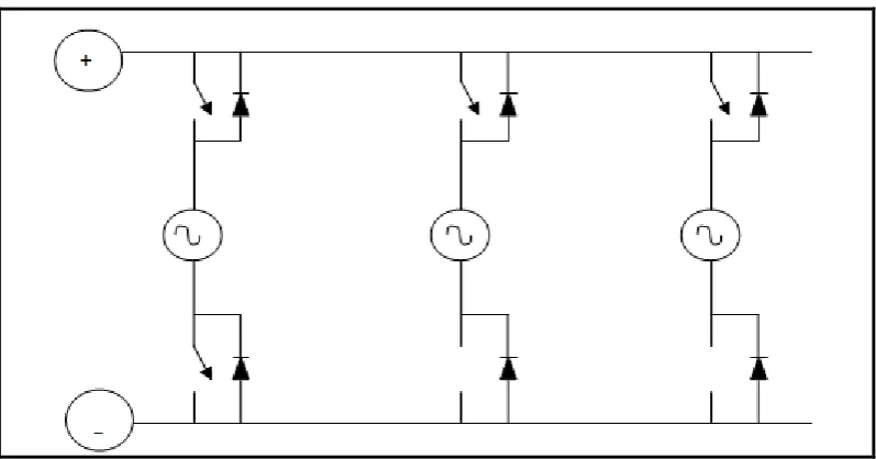
[image:18.595.167.471.216.324.2]A STATCOM is basically a DC-AC voltage source inverter with an energy storage unit, usually a DC capacitor and operates as a controlled Synchronous Voltage Source (SVS) connected to the line through a coupling transformer as shown in Figure 2.3 [4, 8].
Figure 2.3: Schematic configuration of STATCOM diagram [8].
The STATCOM is a shunt reactive power compensating electronic device that generates AC voltage, which intern causes a current of variable magnitude at the point of connection. This injected current is almost in quadrature with the line voltage, thereby emulating an inductive or a capacitive reactance at the point of connection with the transmission line. The functionality of the STATCOM model is verified by regulating the reactive current flow through it. This is useful to generate or absorb reactive power for regulating the line voltage of the bus where the STATCOM is connected [4, 5, 8, 13].
2.4.2 Operation of STATCOM
(2.1)
Where:
Q = Reactive power.
VSTATCOM = Magnitude of STATCOM output voltage. VS = Magnitude of system voltage.
X = Equivalent impedance between STATCOM and the system.
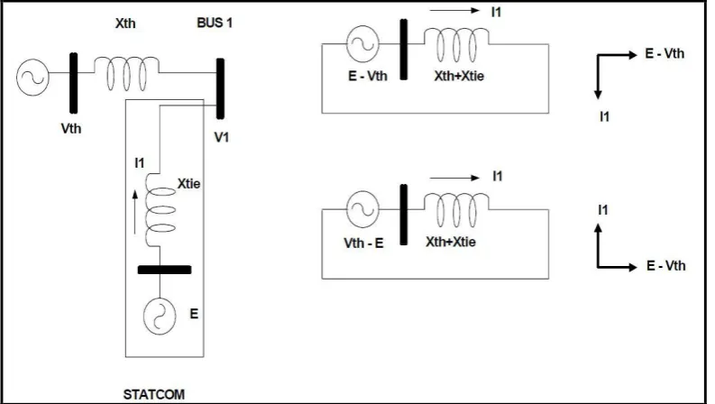
[image:19.595.123.520.498.722.2]Figure 2.4 demonstrates a simplified diagram of the STATCOM with an inverter voltage source, E and a tie reactance, Xtie connected to an ac system with voltage source, Vth and a Thevenin reactance, Xth. When the converter voltage is greater than the system voltage, the STATCOM “sees” an inductive reactance connected at its terminal. Hence, the system “sees” the STATCOM as a capacitive reactance and the STATCOM is operating in a capacitive mode. The current flows from the STATCOM to the AC system, and the device generates reactive power. In this case, the system draws capacitive current that leads by and angle of 90° the system voltage, assuming that the converter losses are equal to zero [14, 15].
2.4.3 Circuit Configuration of STATCOM
For STATCOM, there are two types of circuit configuration which are multipulse converter and multilevel converter. Both of these types have different circuit connection and different operation
[image:20.595.161.480.361.460.2]. In the multipulse converter, the 3-phase bridges are connected in parallel on the DC side as shown in Figure 2.5. The bridges are magnetically coupled via a zigzag transformer. The transformer is usually arranged in order to make the bridges appear in series viewed from the AC sides. Each windings of the transformer is phase shifted. This is to eliminate selected harmonics and produce a multipulse output voltage. Pulse Width Modulation (PWM) is applied to improve the harmonics content, at the expense of higher switching and snubber loss, plus reduced the fundamental of var rating [14, 15, 16].
Figure 2.5: Multipulse converter diagram [16].
Figure 2.6: Cascade multilevel converter diagram [16].
2.4.4 Advantages of STATCOM
STATCOM has many advantages over the other compensators. The advantages of STATCOM can be summarized such as:
i. It has short term overload capability of ~20%
ii. It requires 15-35% less MVA rating then SVC to deliver same level of performance for the system steady state power transfer, dynamic voltages support, and transient stability performance.
iii. It can act as voltage source in stating other converter based equipment. iv. It can be used together with other type of compensations equipment. v. It does not require large harmonic filter.
The other advantages are STATCOM has a dynamic performance far exceeding the other var compensators. The overall system response time of STATCOM can reach 10ms or less. STATCOM has the ability to maintain full capacitive output current at low system voltage, which it makes STATCOM become more effective than SVC in improving the transient stability.
2.5 Introduction to SSSC
The SSSC is generally connected in series with the transmission line with the arrangement as shown in Fig 2.3. The SSSC comprises a coupling transformer, a magnetic interface, voltage source converters (VSC) and a DC capacitor. The coupling transformer is connected in series with the transmission line and it injects the quadrature voltage into the transmission line.
The magnetic interface is used to provide multi-pulse voltage configuration to eliminate low order harmonics. The injected voltage of the coupling transformer Vs
[image:22.595.205.433.296.501.2]is perpendicular to the line current IL [4, 8].
Figure 2.7: Simplified diagram of SSSC [8].
P = V2 sin δ ( 2.2)
X
Where:
P = Real power transmission over a single line
V = The sending end and receiving end voltage (assuming Vs = VR = V) X = The line impedance
δ = The power angle
[image:23.595.152.486.402.496.2]SSSC is a power converter connected in series with the transmission line and it injects a voltage in quadrature with the line current to emulate a series capacitive or inductive reactance into the transmission line. A SSSC equipped with energy storage system and/or absorbing is also able to exchange real power with power system [4, 8, 19].
Figure 2.8: Line diagram of SSSC [19].
Reactive power exchange is controlled by the magnitude of the injected voltage to the transmission line, and angle control is used to regulate the active power exchange. The inductive or capacitive mode of operation is set by the injected voltage phase angle with respect to the transmission line current. When injected voltage is leading the line current, reactive power is absorbed and SSSC operates in inductive mode. In capacitive mode injected voltage is lagging the line current and injects reactive power to the transmission line [20].
In the equivalent circuit of an SSSC compensated system, the SSSC is represented by a voltage source and impedance (Lr,Rr). The SSSC is connected between buses 1 and 2. The pair (L1, R) represents the line and L2 represents a
2.5.1 Function of SSSC
The main function of the SSSC is to control the real power flow. This can be accomplished either by direct control of the line current (power) or alternatively by indirect control of the compensating impedance, Xs, or the compensating voltage, Vc (1). The direct power flow control has the advantage of maintaining the transmitted power in a closed loop manner by the defined reference. However under some network contingency, the maintenance of the constant power flow may not be either possible or even desirable. Therefore in some applications the impedance (or voltage) control that maintains the impedance characteristic of the line may be preferred from the operating standpoint. The degree of series impedance compensation, S, is usually expressed as the ratio of the series injected reactance Xs, to the line reactants, Xl, S = Xs/Xl. Therefore for a capacitive series compensation, the line series reactants is Xline = Xl - Xs, where Xs =S Xl.
Similarly for an inductive series compensation tile line series reactance is Xline = Xl + Xl where Xs = SXl. The basic function of tile control system is to keep the SSSC voltage, Vc in quadrature with the line current IL and control the
magnitude of Vc to meet the compensation requirement, which is the degree of series compensation [19, 20].
2.5.2 Operation of SSSC
The control structure of SSSC is shown in Fig. 2.9. The basic synchronization signal, θ, is the phase angle of line current. The SSSC injected impedance is measured ms the ratio of q-axis voltage of the SSSC, Veq to the magnitude of line current, IL This impedance is then compared with the reference compensation impedance SXl.
A PI controller generates the required phase displacement Δα in order to charge or discharge the dc capacitor. A negative Δα yields to the real power flow from the transmission system to the SSSC and charges the dc capacitor, while a positive Δα discharges the dc capacitor, When Xref is negative Vc lags IL by 90o
plus Δα (capacitive compensation) and when it is positive Vc leads IL by 90o
plus Δα (inductive compensation). The final output of the control system is phase angle of the SSSC output voltage θ.
Figure 2.9: Control structure of SSSC [20].
Basically, a SSSC generates on its output terminals a sinusoidal voltage, with controllable amplitude, in quadrature (nearly) with the transmission line current. Consequently, the injected voltage emulates either a capacitive or an inductive reactance in series with the transmission line that increases or decreases the total transmission line reactance.
As a result, the power flow will change in the line. Hence, the SSSC is a powerful device to control transmission line impedance, and therefore the power flow, independent of the line current. ln fact, reactive power exchange is controlled by the magnitude of the injected voltage to the transmission line, and angle control is used to regulate the active power exchange [19, 20].
2.5.3 Advantages of SSSC
The SSSC is typically applied to correct the voltage during a fault in the power system. However, it also has several advantages during normal conditions [20]: i. Power factor correction through continuous voltage injection and in
iii. It can also help to cover the capacitive and reactive power demand. iv. Power flow control.
v. Reduces harmonic distortion by active filtering.
2.6 Introduction to UPFC
Unified Power Flow Controller (or UPFC) is an electrical device for providing fast-acting reactive power compensation on high-voltage electricity transmission networks. It uses a pair of three-phase controllable bridges to produce current that is injected into a transmission line using a series transformer. The controller can control active and reactive power flows in a transmission line. The UPFC uses solid state devices, which provide functional flexibility, generally not attainable by conventional thyristor controlled systems.
The UPFC is a combination of a static synchronous compensator (STATCOM) and a static synchronous series compensator (SSSC) coupled via a common DC voltage link. The UPFC concept was described in 1995 by L. Gyugyi of Westinghouse. The UPFC allows a secondary but important function such as stability control to suppress power system oscillations improving the transient stability of power system [4, 8, 10, 21].
2.6.1 Function of UPFC
Figure 2.10: Simplified diagram of SSSC [8].
The UPFC was devised for the real time control and dynamic compensation of ac transmission systems, providing multifunctional flexibility required to solve many of the problems facing the delivery industry. Within the framework of traditional power transmission concepts, the UPFC is able to control, simultaneously or selectively, all the parameters affecting power flow in the transmission line (i.e., voltage, impedance and phase angle), and this unique capability is signified by the adjective “unified” in its name. Alternatively, it can independently control both the real and reactive power flows in the line. The UPFC not only performs the functions of the STATCOM, TCSC, and the phase angle regulator but also provides additional flexibility by combining some of the functions of these controllers.
The Unified Power Flow Controller (UPFC) consists of two voltage sourced converters using power switches, which operate from a common DC circuit of a DC-storage capacitor. This arrangement functions as an ideal ac to ac power converter in which the real power can freely flow in either direction between the ac terminals of the two converters and each converter can independently generate (or absorb) reactive power at its own ac output terminal [8, 21, 22].
2.6.2 Operation of UPFC
The real power exchanged at the ac terminal (i.e., at the terminal of insertion transformer) is converted by the inverter into dc power that appears at the dc link as positive or negative real power demanded. The reactive power exchanged at the ac terminal is generated internally by the inverter.
Figure 2.11: UPFC as 2-port device [22]
The basic function of Inverter 1 is to supply or absorb the real power demanded by Inverter 2 at the common dc link. This dc link power is converted back to ac and coupled to the transmission line via a shunt connected transformer. Inverter 1 can also generate or absorb controllable reactive power, if it is desired, and there by it can provide independent shunt reactive compensation for the line. It is important to note that where as there is a closed “direct” path for the real power negotiated by the action of series voltage injection through Inverters 1 and 2 back to the line, the corresponding reactive power exchanged is supplied or absorbed locally by inverter 2 and therefore it does not flow through the line.
Thus, inverter 1 can be operated at a unity power factor or be controlled to have a reactive power exchange with the line independently of the reactive power exchanged by the by the Inverter 2. This means there is no continuous reactive power flow through UPFC [8, 21, 22, 23].
2.7 Previous Studies
power flow analysis are applied to compute the power transfer capability without the insertion SSSC. With the analysis, the maximum loading parameter, total generation and generation are obtained by wind. Found that the line that connecting bus 2 and 6 was congested. With this finding (the congested line) they eventually had determined the place for the insertion of SSSC in the system. Then, utilized the continuous power flow analysis in order to compute the power transfer capability after injecting SSSC in series with line 2-6. After the analysis had been made, the maximum loading parameter, total generation and generation are obtained by wind farm. Having the power flow results before and after the insertion of the SSSC, by made a comparison based on the acquired data, and it is shown that the maximum loading parameter, total generation and generation by wind farm increases. Therefore, based on the comparison made, concluded that the power transfer capability of the network increase [24].
2.8 Chapter Summary
REFERENCES
[1] S. K. Khadem, M. Basu and M.F. Conlon. Power Quality in Grid connected Renewable Energy Systems: Role of Custom Power Devices. School of Electrical Engineering Systems. Dublin Institute of Technology. 2010.
[2] I. El-Samahy, El-Saadany. The Effect of DG on Power Quality in a Deregulated Environment. IEEE Power Engineering Society General Meeting 2005. 2969-2976.
[3] Wikipedia (2013). Power Flow Study. Retrieved on January 12, 2013, from http://en.wikipedia.org/wiki/Power_flow_study
[4] Wikipedia (2013). Flexible AC Transmission System. Retrieved on January
12, 2013, from
http://en.wikipedia.org/wiki/Flexible_AC_transmission_system
[5] Arti Pateriya, Nitin Saxena and Manoj Tiwari. Transfer Capability Enhancement of Transmission Line using Static Synchronous Compensator
(STATCOM). International Journal of Advanced Computer Research. Volume-2 Number-4 Issue-7 December-2012. 83-88.
[6] B.Gopinath and C.Keerthana. Simultaneous Tuning of Power System Damping Controllers using Pi Controller. International Journal of Communications and Engineering. Volume 04 – No.4. Issue: 04 March2012. 24-30.
[7] L. Gyugyi. The Unified Power Flow Controller A New Approach to Power Transmission Controller. IEEE Transaction of Power Delivery. Volume 10, No. 2, April 1995, 1085-1097.
[9] The Symmetrical Hybrid Power Flow Controller (2013). Introduction to Flexible AC Transmission (FACTS). Retrieved on January 12, 2013, from http://www.hpfc.ca/facts.html
[10] Ashwin Kumar Sahoo. An Improved UPFC Control to Enhance Power System Stability. Modern Applied Science. Vol. 4, No. 6; June 2010. 37-48 [11] Hasan Fayazi Boroujeni. Robust Controller Design for LFO Damping.
International Journal of Academic Research in Applied Science. 2012. 1-8 [12] G.SUNDAR, S.RAMAREDDY. Digital Simulation of Multilevel Inverter
Based STATCOM. Journal of Theoretical and Applied Information Technology. 2009. 19-24.
[13] M.Mohammadha Hussaini. Dynamic Response of Wind Power Generators using STATCOM. International Journal of Engineering and Technology Vol.2 (4), 2010, 297-304.
[14] Surinder Chauhan. Designing of STATCOM Controllers for Transient Stability Improvement of Two Machine System. Master of Engineering. Thapar University Patiala, Punjab-147004. July 2012.
[15] Bhim Singh and Sanjay Gairola. A Zigzag Connected Auto-Transformer Based 24-Pulse AC-DC Converter. Journal of Electrical Engineering & Technology, Vol. 3, No. 2, 2008. 235-242.
[16] Surin Khomfoi and Leon M. Tolbert. Multilevel Power Converters. The University of Tennessee. 1-50.
[17] Oscar Plasencia. Modeling and Analysis of a Four-Switch Buck-Boost Dynamic Capacitor. Masters of Science in Electrical Engineering. California Polytechnic State University. December 2011.
[18] Ricardo Dávalos Marín. Detailed analysis of a multi-pulse STATCOM. Unidad Guadalajara, May 2003.
[19] Dr. Y. Rajendra Babu. Design of d-q Domain Control Strategy for Static Synchronous Series Compensator. International Journal of Engineering Research & Technology (IJERT), Vol. 2 Issue 4, April - 2013. 904-908. [20] Power Quality In Electrical Systems (2013). Static Synchronous Series
Compensator (SSSC). Retrieved on January 12, 2013, from
[21] Wikipedia (2013). Unified Power Flow Controller. Retrieved on January 12, 2013, from http://en.wikipedia.org/wiki/Unified_Power_Flow_Controller [22] T. Nireekshana et. al. Modelling and Control Design of Unified Power Flow
Controller for Various Control Strategies. International Journal of Engineering Science and Technology, Vol. 2(11), 2010, 6293-6307.
[23] L.Gyugyi. Unified Power Flow Concept for Flexible Ac Transmission Systems. IEEE Proc-C, Vol.139, No.4, July1992, 323-332.
[24] Liangzhong Yao. Congestion Management of Transmission System using FACTS. IEEE/PES Transmission and Distribution Conference & Exhibition: Asia and Pacific Dalian, China, 2005. 1-5.
[25] Mahdad, B. Strategy of Location and Control of FACTS Devices for Enhancing Power Quality. IEEE MELECON, Benalmádena, Málaga, Spain. May 2006.
[26] Sameh Kamel Mena Kodsi.. Modeling and Simulation of IEEE 14 bus System with FACTS Controllers. IEEE Student Member, 2003.
[27] P.K. Iyambo, and R. Tzoneva.. Transient Stability Analysis of the IEEE 14-Bus Electric Power System. IEEE Member, 2007.
[28] F. Milano. An Open Source Power System Analysis Toolbox. IEEE Transactions on Power Systems. August 2005. IEEE. Volume 20, Issue 3. 1199-1206.
![Figure 1.1: Example of control system topology [1].](https://thumb-us.123doks.com/thumbv2/123dok_us/8772163.899477/9.595.117.523.70.315/figure-example-of-control-system-topology.webp)
![Figure 2.2: A VSC interfaced to a transmission line- P and Q exchange [8].](https://thumb-us.123doks.com/thumbv2/123dok_us/8772163.899477/17.595.132.510.67.317/figure-vsc-interfaced-transmission-line-p-q-exchange.webp)
![Figure 2.3: Schematic configuration of STATCOM diagram [8].](https://thumb-us.123doks.com/thumbv2/123dok_us/8772163.899477/18.595.167.471.216.324/figure-schematic-configuration-statcom-diagram.webp)
![Figure 2.5: Multipulse converter diagram [16].](https://thumb-us.123doks.com/thumbv2/123dok_us/8772163.899477/20.595.161.480.361.460/figure-multipulse-converter-diagram.webp)
![Figure 2.7: Simplified diagram of SSSC [8].](https://thumb-us.123doks.com/thumbv2/123dok_us/8772163.899477/22.595.205.433.296.501/figure-simplified-diagram-of-sssc.webp)
![Figure 2.8: Line diagram of SSSC [19].](https://thumb-us.123doks.com/thumbv2/123dok_us/8772163.899477/23.595.152.486.402.496/figure-line-diagram-of-sssc.webp)
![Figure 2.9: Control structure of SSSC [20].](https://thumb-us.123doks.com/thumbv2/123dok_us/8772163.899477/25.595.152.509.74.351/figure-control-structure-of-sssc.webp)
![Figure 2.10: Simplified diagram of SSSC [8].](https://thumb-us.123doks.com/thumbv2/123dok_us/8772163.899477/27.595.185.455.68.205/figure-simplified-diagram-of-sssc.webp)
