International Journal of Emerging Technology and Advanced Engineering
Website: www.ijetae.com (ISSN 2250-2459, Volume 2, Issue 10, October 2012)137
A Novel Method for Energy Optimization of Dynamic Voltage
Restorer by Using Phase Advance Compensation and In-Phase
Technique
Jacob P Varghese
1, N. Venugopalan
2, T. G. Sanish Kumar
31M.Tech Student, 2Associate Professor, 3Assisstant Professor, Dept. of Electrical and Electronics Engg., Government
Engineering College Thrissur, Kerala, India
Abstract—Nowadays, power quality issues are the major problem faced by the utilities, as well as by both industrial and commercial electrical consumers. Voltage sag and swell is the origin of 90% power quality problems. A dynamic voltage restorer is a custom power device used to correct the voltage disturbances by injecting voltage as well as power into the system. In this paper, a new control strategy is proposed, so as to reduce the energy used to compensate the voltage sag/swell. In this proposed control strategy, when balanced sag occurs, the voltage compensation will result in phase advancement of the load voltage and when unbalanced sag occurs, compensated load voltage will be in-phase with the sag-voltage. The control logic has been extended to control the voltage swell also. By using this control, the active power injection/absorption during the balanced sag/swell is reduced. The simulations have been done on the MATLAB. Simulation results show that the voltage compensation occurs for voltage sag and swell.
Keywords— Dynamic Voltage Restorer, Energy Optimization, In-phase Compensation, Phase Advance Compensation.
I. INTRODUCTION
Nowadays, power quality in electric networks is one of the most concerned areas of electric power system [1]. The power quality has serious economic implications for consumers, utilities and electrical equipment manufacturers.
In general, it is possible to consider voltage sag and swell as the origin of 10 to 90% power quality problems [2] [3] [4]. The voltage swells are not much considered as voltage sags because they are not common in distribution systems. Among the several novel custom power devices, the dynamic voltage restorer (DVR) for application in distribution systems is a recent invention. A dynamic voltage restorer is a custom power device used to correct the voltage disturbances by injecting voltage into the system.
For the protection of higher power sensitive loads where the energy storage capabilities of uninterruptible power supplies (UPS) become very costly, the dynamic voltage restorer (DVR) shows promise in providing a more cost effective solution.
[image:1.612.331.556.411.586.2]Voltage sag and swell affects the industries very much, because the involved losses can reach very high values. They can cause sensitive equipment (such as found in semiconductor or chemical plants) to fail or shut down [5] [6] and will lead to loss of production [7]. Therefore, cost-effective solutions, which can help such sensitive loads, ride through momentary power supply disturbances, have attracted much research attention.
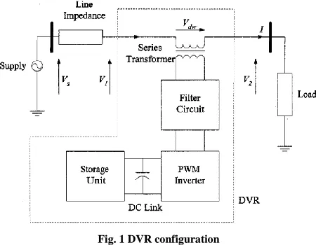
Fig. 1 DVR configuration
International Journal of Emerging Technology and Advanced Engineering
Website: www.ijetae.com (ISSN 2250-2459, Volume 2, Issue 10, October 2012)138
By using combination of these methods, energy optimization is obtained during injection of voltage, when there is balanced sag. The simulations have been done on the MATLAB platform. Simulation results show that the voltage compensation occurs for voltage sag and swell.
II. DYNAMIC VOLTAGE RESTORER
DVR is a power electronic based device that injects voltage into the system to regulate the load side voltage [8] [9] [10].
A schematic diagram of the DVR incorporated into a distribution network [11] is shown in Fig. l. In the Fig., VS is the source voltage, V1 is the incoming supply voltage before compensation, Vdvr is the series injected voltage of the DVR, and I is the line current. V2 is the load voltage. The restorer typically consists of an injection transformer, the secondary winding of which is connected in series with the distribution line. A voltage-sourced PWM inverter bridge is connected to the primary of the injection transformer and an energy storage device is connected at the dc-link of the inverter bridge. The inverter bridge output is filtered by using an LC filter. The injection of an appropriate Vdvr during a voltage disturbance requires a certain amount of real and reactive power supply from the DVR.
The voltage sag or swell is caused due to short circuit in the adjacent feeder(s) or different faults occur in source side. Magnitude and phase of the voltage variation in the source side, is continuously monitoring at the Point of Common Coupling by means of a control algorithm. A fault current in the grid can lead to a reduced magnitude of the voltage at the Point of Common Coupling. Under this circumstances the DVR generate a compensating voltage corresponding to the estimated magnitude of voltage variation by means of a DC-source. This compensating voltage is injected to the distribution system via an injection transformer and stabilizes the load side voltage
III. CONTROL METHOD FOR DVR
As the DVR is required to inject active power into the distribution line during the period of compensation, the capacity of the energy storage unit can become a limiting factor in the disturbance compensation process. For sags of long duration, this could result in poor load ride-through capability. It is not necessary for the load voltage to be in-phase with the pre sag voltage [12].
Indeed, the load voltage can lie anywhere on the periphery of a circle, the radius of which equals to the amplitude of the pre sag voltage [11] [12]. Phase Advance Compensation (PAC) uses this method, in which, all the three phase voltages are progressively advanced by a certain angle to minimize the amount of real power supplied by the DVR.
A new method, which is a combination of in-phase compensation method and phase advance compensation method, is presented in this paper. This method allows the separate control of each of the phase. For balanced sags/ swells, phase-advance compensation method is used. For unbalanced sags/ swells, in-phase compensation method is used. This is to avoid further severe unbalance, due to phase advance in the load voltage. By using this method, active power injected during balanced sag and swell can be reduced.
The algorithm for the proposed method is as follows.
Step 1: Start
Step 2: Find V1,, V2, δ.
Step 3: Check whether the load voltage is within limits. If yes, go to step 3 and continue checking, else go to next step.
Step 4: Check whether the sag/ swell is balanced. If yes, go to step 5, else go to step 6
Step5: Compute the advance angle, α and then the compensating voltage, Vdvr and then the injecting angle, θ
Step 6: Assign the advance angle, α=0 and then compute the compensating voltage, Vdvr and then the injecting angle, θ
Step 7: Generate switching pulses.
A. Phase- Advance Method For voltage sag
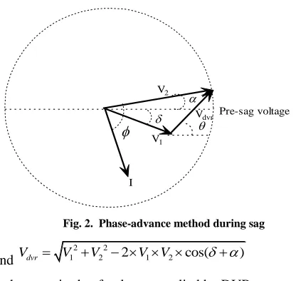
Fig. 2 represents a phasor diagram of the power distribution system during sag, where V1, V2 and Vdvr are the supply voltage magnitude during sag, compensated load voltage magnitude and the DVR voltage magnitude respectively.
I,, δ, α represent load current, load power factor angle, supply voltage phase angle deviation and load voltage advance angle respectively. The angle of injection of compensating voltage is given as
1 2 1
2 1
sin sin
tan ( )
cos cos
V V
V V
International Journal of Emerging Technology and Advanced Engineering
Website: www.ijetae.com (ISSN 2250-2459, Volume 2, Issue 10, October 2012)139
[image:3.612.47.559.92.732.2]
Fig. 2. Phase-advance method during sag
and
2 2
1 2 2 1 2 cos( ) dvr
V V V V V
(2)
is the magnitude of voltage supplied by DVR.
The control of real and reactive power exchange is possible with the adjustment of the phase angle α for known values of , δ,V1 and V2. If Pin be the input power from the source, Pout be the load power and Pdvr be the active power supplied by the DVR.
Then,
Pdvr=Pin-Pout
=
3
2 1
1
3 cos( ) j jcos( j)
j
V I V I
(3)
For minimum power operation of DVR, there may be two operating conditions.
1. Operation at Pdvr=0
Then,
3
2 1
1
3 cos( ) j jcos( j) 0 j
V I V I
On solving, 1 2 2 2 1 13 cos( )
cos ( )
( cos( )) ( sin( ) )
opt j
j j j j
V V V (4)
2. Operation at Pdvr>0
If the voltage sag is so severe, the DVR has to supply active power also. Then, the optimum value of α can still
be calculated by setting
0 dvr
dP d
0 dvr
dP
d
becomes3
1 1
sin( ) 0
j j j
j
V I
Then,
opt
j (5)B. Phase- Advance Method For voltage swell
Fig.3 represents a phasor diagram of the power distribution system during swell, where V1, V2 and Vdvr are the supply voltage magnitude during swell, compensated load voltage magnitude and the DVR voltage
magnitude respectively. I, , δ, α represent load current, load power factor angle, supply voltage phase angle deviation and load voltage advance angle respectively.
The angle of injection of compensating voltage is given as
1 1 2
1 2
sin sin
tan ( )
cos cos V V V V
(6)
The magnitude of voltage supplied by DVR is
2 2
1 2 2 1 2 cos( )
dvr
V V V V V
(7)
The control of real and reactive power exchange is possible with the adjustment of the phase angle α for known values of , δ,V1 and V2. If Pin be the input power from the source, Pout be the load power and Pdvr be the active power supplied by the DVR.
Fig. 3 Phase-advance method during swell
Then,
Pdvr=Pin-Pout
=
3
2 1
1
3 cos( ) j jcos( j)
j
V I V I
(8) V2 V1 Vdvr Pre-sag voltage
[image:3.612.53.261.135.332.2]International Journal of Emerging Technology and Advanced Engineering
Website: www.ijetae.com (ISSN 2250-2459, Volume 2, Issue 10, October 2012)140
For minimum power operation, there may be two operating conditions.
1. Operation at Pdvr=0
The operation of DVR at this mode means, the active power absorbed by the DVR is zero.
Then,
3
2 1
1
3 cos( ) j jcos( j) 0
j
V I
V I
On solving,
1 2
2 2
1 1
3 cos( )
cos ( )
( cos( )) ( sin( ) )
opt j
j j j j
V
V V
(9)
2. Operation at Pdvr<0
If the DVR has to absorb active power, the optimum
value of α can be calculated by setting
0 dvr
dP d
0 dvr
dP
d
becomes3 1 1
sin( ) 0
j j j
j
V I
Then,
opt
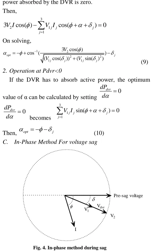
j (10)C. In-Phase Method For voltage sag
[image:4.612.44.289.193.600.2]
Fig. 4. In-phase method during sag
In-phase compensation method can be used for compensating the supply voltage, without any phase difference. So it can be used for unbalanced sag/ swell.
The above control method can be modified as in-phase compensation method, by making the advance angle, α =0 and by making the angle of injection as –δ.
Fig. 4 represents a phasor diagram, where V1, V2 and Vdvr are the supply voltage magnitude during sag, compensated load voltage magnitude and the DVR voltage magnitude respectively
I, , δ, α represent load current, load power factor angle, supply voltage phase angle deviation and load voltage advance angle respectively. The magnitude of voltage supplied by DVR is
2 2
1 2 2 1 2 dvr
V V V V V
(11)
[image:4.612.334.545.264.461.2]D. In-Phase Method For voltage swell
Fig. 5 In-phase method during swell
Fig. 5 represents a phasor diagram, where V1, V2 and Vdvr are the supply voltage magnitude are during swell, compensated load voltage magnitude and the DVR voltage
magnitude respectively. I, , δ, α represent load current, load power factor angle, supply voltage phase angle deviation and load voltage advance angle respectively.
The phase advance compensation method can be modified as in-phase compensation method, by making the advance angle, α =0 and by making the angle of injection as δ. The magnitude of voltage supplied by DVR is
2 2
1 2 2 1 2 dvr
V V V V V
(12)
V2
V1
Vdvr
Pre-sag voltage
I
V2
V1
Vdvr
Pre-sag voltage
International Journal of Emerging Technology and Advanced Engineering
Website: www.ijetae.com (ISSN 2250-2459, Volume 2, Issue 10, October 2012)141
IV. TEST SYSTEM AND SIMULATION RESULTS
[image:5.612.328.566.135.486.2]The proposed system is tested on system with parameters as shown in Table I. Simulations were done on the MATLAB® and SIMULINK® platform. The test system is a 415 v, distribution system, with 50 Hz supply. An R-L load of 10 kW with 0.8 power factor is used. The simulation system parameters are given in the Table I.
TABLE I SYSTEM PARAMETERS
System voltage 415 V
System frequency 50Hz
Load 10kW at .8 power
factor 3 phase system
Injection transformer turns ratio
1:1
Filter resistance 0.2 Ω
Filter inductance 0.5 mH
Filter capacitance 400 µF
A. Test System Description
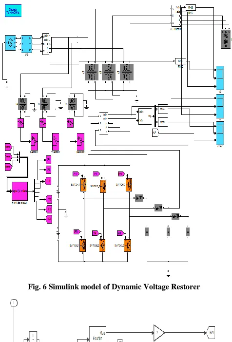
The Fig. 6 shows the SIMULINK® model of Dynamic Voltage Restorer. Each phase is controlled separately. The voltage waveform sensed by the voltage sensor device is divided by a constant value to obtain the per unit value of the system voltage. By using the Fourier block in MATLAB® library, magnitude of the voltage is found out. By using a phase locked loop and the Fourier block, the reference voltage magnitude is found out.
The phase difference of the system voltage is found out by comparing it with a sine wave. A reference sine wave is generated by using the sine wave generator block. The load power factor is assumed to be constant for the load for simplicity. By comparing the system voltage with the sine wave output of the phase locked loop, the single phase error voltage signal is generated. This is shown in the Fig. 7
After finding the voltage parameters, V1, V2 , and δ , the advance angle, α and then the Vdvris found out using the equations as explained above. The output of this block is smoothened by using the Fourier block along with a user defined block in the MATLAB® library. This is shown in the Fig. 8.
Fig. 6 Simulink model of Dynamic Voltage Restorer
[image:5.612.52.279.236.384.2]International Journal of Emerging Technology and Advanced Engineering
Website: www.ijetae.com (ISSN 2250-2459, Volume 2, Issue 10, October 2012)142
[image:6.612.325.569.151.683.2]An additional control block is given to switch between the in-phase compensation method and phase advance compensation method. There are two control block to generate the signal for compensating voltages, which means, the in-phase compensating voltage, and the phase advance compensation voltage. Whenever there is a balanced sag/ swell, this user defined MATLAB® function block will select the phase advance compensating voltage signal. This is shown Fig. 9. Whenever there is unbalanced sag/ swell, this block will select the in-phase compensating voltage signal. The control logic for the switching block searches whether the twice of a single phase error is greater than 95% of the sum of other two phase’s error voltage. If this condition is met, then the switching block will assume it as balanced sag/ swell and selects the signal for phase advance compensation voltage.
[image:6.612.53.295.246.616.2]Fig. 8 Generation of compensating voltage signal
Fig. 9 Switching logic
B. Simulation Results and Discussion
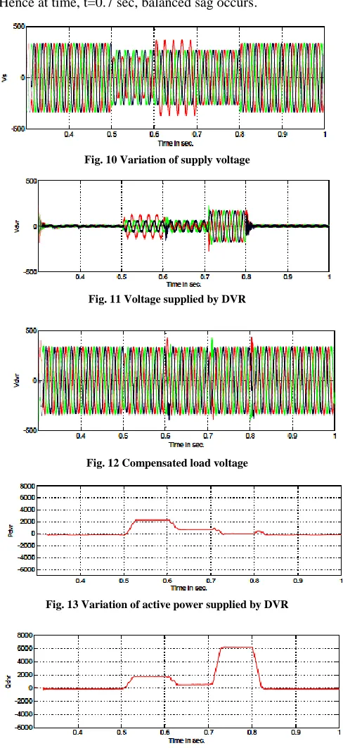
Fig. 10 shows supply voltage, when a fault occurs at supply side. At time, t=0.5 sec, there is 30% sag at single phase (R phase), 20% sag at other two phases (Y and B phase). At time, t=0.6 sec, there is a 10% swell occurring at the same phase(R phase), which is already overloaded.
At time t=0.7 sec, there is 20% sag at R-phase too. Hence at time, t=0.7 sec, balanced sag occurs.
Fig. 10 Variation of supply voltage
Fig. 11 Voltage supplied by DVR
Fig. 12 Compensated load voltage
Fig. 13 Variation of active power supplied by DVR
[image:6.612.66.300.335.520.2]International Journal of Emerging Technology and Advanced Engineering
Website: www.ijetae.com (ISSN 2250-2459, Volume 2, Issue 10, October 2012)143
Fig. 15 Advance angleFig. 16 RMS value of supply voltage
Fig. 17 RMS value of load voltage
Fig. 11 shows the voltage supplied by the DVR during the time at which, the fault occurs. From time, t=0.5 sec. to 0.7 sec., the DVR injects voltage to each phase by in-phase compensation method. From time, t=0.7 sec. to t=0.8 sec., the DVR injects voltage by phase advance compensation method.
Fig. 12 shows the compensated load voltage. It shows that load voltage is within the desired limits.
Fig. 13 shows the variation of active power supplied by the DVR during the fault period. From time, t=0.5sec. to time, t=0.7 sec, the power is supplied using the in-phase method, since it is an unbalanced fault. From time, t=0.7 sec. to time, t=0.8 sec, the power is supplied using the phase advance method.
Fig. 14 shows the variation of reactive power supplied by the DVR during the fault period. From time, t=0.5sec. to time, t=0.7 sec, the power is supplied using the in-phase method, since it is an unbalanced fault. From time, t=0.7 sec. to time, t=0.8 sec, the power is supplied using the phase advance method.
-6000 -4000 -2000 0 2000 4000 6000
-0.6 -0.4 -0.2 0 0.2 0.4 0.6 Per unit difference in Supply voltage
ACTIVE POWER INJECTED BY DVR USING IN-PHASE METHOD REACTIVE POWER INJECTED BY DVR USING IN-PHASE METHOD
Fig. 18 Power supplied by in-phase method for balanced faults
-8000 -6000 -4000 -2000 0 2000 4000 6000 8000 10000
-0.6 -0.4 -0.2 0 0.2 0.4 0.6 Per unit difference in Supply voltage
ACTIVE POWER INJECTED BY DVR USING PAC METHOD REACTIVE POWER INJECTED BY DVR USING PAC METHOD
Fig. 19 Power supplied by phase advance method for balanced faults
Fig. 51 shows the variation of advance angle of the voltage supplied by the DVR, during the fault period. From time, t=0.5sec. to time, t=0.7 sec, the power is supplied using the in-phase method, since it is an unbalanced fault. Hence advance angle is zero. From time, t=0.7 sec. to time, t=0.8 sec, the power is supplied using the phase advance method. Hence there is phase advance and the advance angle is shown in the Fig. 15
International Journal of Emerging Technology and Advanced Engineering
Website: www.ijetae.com (ISSN 2250-2459, Volume 2, Issue 10, October 2012)144
At time, t=0.6 sec, there is a 10% swell occurring at the same phase(R phase), which is already overloaded. At time t=0.7 sec, there is 20% sag at R-phase. Hence from time, t=0.7 sec, balanced sag occurs.
Fig. 17 shows the RMS value of load voltage. It shows that the compensated load voltage is within the desired limits.
Fig. 18 shows the active power and reactive power supplied by the DVR for a balanced fault, using the in-phase method. A fault from 50% sag to 40% swell is checked here.
Fig. 19 shows the active power and reactive power supplied by the DVR for a balanced fault, using the phase advance method. A fault from 50% sag to 40% swell is checked here.
-5000 -4000 -3000 -2000 -1000 0 1000 2000 3000 4000 5000 6000
-0.6 -0.4 -0.2 0 0.2 0.4 0.6
Per unit difference in Supply voltage
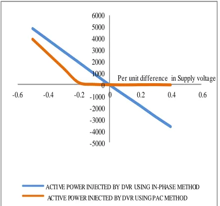
[image:8.612.331.556.174.578.2]ACTIVE POWER INJECTED BY DVR USING IN-PHASE METHOD ACTIVE POWER INJECTED BY DVR USING PAC METHOD
Fig. 20 Active power supplied by two methods for balanced faults
Fig. 20 shows the active power supplied by the DVR for a balanced fault, using the in-phase method and phase advance method. A fault from 50% sag to 40% swell is checked here.
Fig. 21 shows the reactive power supplied by the DVR for a balanced fault, using the in-phase method and phase advance method. A fault from 50% sag to 40% swell is checked here.
Fig. 22 shows the variation of advance angle, with respect to a fault from 50% sag to 40% swell.
-8000 -6000 -4000 -2000 0 2000 4000 6000 8000 10000
-0.6 -0.4 -0.2 0 0.2 0.4 0.6
Per unit difference in Supply voltage
REACTIVE POWER INJECTED BY DVR USING IN-PHASE METHOD REACTIVE POWER INJECTED BY DVR USING PAC METHOD
Fig. 21 Reactive power supplied by two methods for balanced faults
-30 -20 -10 0 10 20 30 40 50
-0.6 -0.4 -0.2 0 0.2 0.4 0.6 Angle in
Degrees
Per unit difference in Supply voltage
[image:8.612.58.280.318.526.2]ADVANCE ANGLE , ALPHA; BY USING PAC METHOD
Fig. 22 Variation of advance angle
[image:8.612.331.555.397.601.2]International Journal of Emerging Technology and Advanced Engineering
Website: www.ijetae.com (ISSN 2250-2459, Volume 2, Issue 10, October 2012)145
V. CONCLUSION
This paper presents and investigates a new method for optimization of active power. A Simulink model is presented in this paper and compensation capacity of the DVR during various fault conditions are investigated. The effectiveness of the method is verified by simulation results. The obtained result shows that the DVR optimizes the active power for balanced sag/ swell.
The proposed DVR uses a combination of in-phase method and phase advance compensation method for mitigating the sag/ swell. A number of fault conditions were tested by using the newly developed control method. The test result shows that the fault is mitigated and the load voltage is within the desired limits. The DVR is tested for a fault from 50% sag to 40% swell. And the obtained test result shows that the load voltage is within the normal operating voltage. Balanced and unbalanced fault conditions are also tested.
REFERENCES
[1] Ahad Kazemi and Ali Azhdast,―Implementation of a Control Strategy for Dynamic Voltage Restorer(DVR) and Dynamic Voltage Compensator(DVC)‖ IEEE , 2009.
[2] Chris Fitzer, Mike Barnes, and Peter Green, ―Voltage Sag Detection Technique for a Dynamic Voltage Restorer‖, IEEE TRANSACTIONS ON INDUSTRY APPLICATIONS, Vol. 40, No. 1, February 2004.
[3] N. Hamzah, M. R. Muhamad, P. M. Arsad, ―Investigation On The Effectiveness Of Dynamic Voltage Restorer For Voltage Sag Mitigation‖, The 5th Student Conference on Research and Development, Malaysia, 2007.
[4] Anita Pakharia, Manoj Gupta, ―Dynamic Voltage Restorer For Compensation Of Voltage Sag And Swell: A Literature Review‖, International Journal of Advances in Engineering & Technology, July 2012.
[5] Carl Ngai-man Ho, Henry S. H. Chung, and Keith T. K. Au, ―Design and Implementation of a Fast Dynamic Control Scheme for Capacitor-Supported Dynamic Voltage Restorers‖, IEEE TRANSACTIONS ON POWER ELECTRONICS, Vol. 23, No. 1, January 2008.
[6] Rosli Omar and Nasrudin Abd Rahim, ―Mitigation Of Voltage Sags/Swells Using Dynamic Voltage Restorer (DVR)‖, ARPN Journal of Engineering and Applied Sciences, Vol. 4, No. 4, June 2009.
[7] Christoph Meyer, Christoph Romaus, Rik W. De Doncker, ―Optimized Control Strategy for a Medium-Voltage DVR‖, Institute for Power Electronics and Electrical Drives, 2005.
[8] M.A.Taghikhani, ―Multi-Loop Control System Design for Phase Advanced Dynamic Voltage Restorer‖, International Journal of Automation and Power Engineering, April 2012.
[9] Lim Yun Seng, ―Algorithm for Designing the Size of Energy Storage in Dynamic Voltage Restorer‖, First International Conference on Industrial and Information Systems, Sri Lanka, August 2006.
[10] Paisan Boonchiam, Promsak Apiratikul and Nadarajah Mithulananthan, ―Detailed Analysis of Load Voltage Compensation for Dynamic Voltage Restorers‖, Energy Field of Study, Asian Institute of Technology, Thailand, 2006.
[11] D. Mahinda Vilathgamuwa, A. A. D. Ranjith Perera, and S. S. Choi, ―Voltage Sag Compensation With Energy Optimized Dynamic Voltage Restorer‖, IEEE TRANSACTIONS ON POWER DELIVERY, VOL. 18, NO. 3, JULY 2003