International Journal of Emerging Technology and Advanced Engineering
Website: www.ijetae.com (ISSN 2250-2459,ISO 9001:2008 Certified Journal, Volume 3, Issue 5, May 2013)
303
GIS Applications in Land Use and Land Development of a City
R. Laxmana Reddy
1, B. Apoorva
2, S. Snigdha
3, K. Spandana
41Asst. Prof., CED, CBIT, Andhra Pradesh, India. 2,3,4CED, CBIT, Andhra Pradesh, India.
Abstract – Since liberalization was introduced in the year
1991, Indian cities have been experiencing an accelerated pace of growth. This has created opportunities for technocrats and planners alike to guide and develop the process of planned development and management of cities. Efficient urban information system is a vital pre-requisite for planned development as the ever increasing demands in urban planning and management call for co-ordinate application of Geographic Information System (GIS), for sustainable development of urban areas. The availability of satellite images from Google earth has revolutionized the process of thematic mapping and spatial data base creation, specially, in the context of urban and regional planning. Technologies such as GIS have emerged as a powerful tool in integrating and analyzing the various thematic layers along with attribute information to create various planning scenarios for decision making. The ability of GIS to store, manage and manipulate large amounts of spatial data provides urban planners with a powerful tool. This paper focuses on how GIS can be applied to establish, maintain, and analyze urban and land-use information for location and development of industries, educational institutions, housing, water supply, service facilities, sewer systems, etc. The present case study involves the suburbs of Boduppal and Pirzadiguda in Hyderabad city of the state of Andhra Pradesh in India.
Keywords — GIS, GPS, Land Use, Land Development,
Urban Planning, Sustainable Development.
I. INTRODUCTION
1.1 What is GIS?
GIS (Global Information System) is a computer based integrated database management system that stores a large volume of spatial data along with its attribute or non-spatial data which are captured, stored, retrieved, processed and analyzed to provide answers to queries of a geographical nature as and when required. GIS technology integrates common database operations such as query and statistical analysis with the unique visualization and the geographic analysis benefits offered by maps. These abilities distinguish GIS from other information systems and make it valuable to a wide range of public and private enterprises for explaining events, predicting outcomes and planning strategies.
1.2 GIS components
The figure–1 below shows the various components of GIS.
FIGURE – 1
1.3 Computer Hardware
The general hardware component of a geographical information system is the computer or central processing unit. It is linked to a disk drive storage unit, which provides space for storing data and programs. A digitizer, scanner and other device is used to convert data from maps and documents into digital form and send them to computer. A digitizer board is a flat board used to vectorize any map object. A plotter or other kind of display device is used to present the result of the data processing and a tape device is used for storing data or programs on magnetic tape.
1.4 Computer Software
International Journal of Emerging Technology and Advanced Engineering
Website: www.ijetae.com (ISSN 2250-2459,ISO 9001:2008 Certified Journal, Volume 3, Issue 5, May 2013)
304 1.5 Geographic Data
It is the most important component of GIS. Geographic data and related tabular data can be collected, compiled to custom specifications and requirements, or purchased from a commercial data provider. A GIS can integrate spatial data with other existing data resources, often stored in a DBMS. The integration of spatial and tabular data stored in a DBMS is a key functionality afforded by GIS.
1.6 Users
GIS technology has limited value without the people who manage and develop plans for applying it to real world problems. GIS users range from technical specialists (who design and maintain the system) to those who use it to help them perform their daily work.
1.7 Methodology
A successful GIS operates according to a well-designed implementation plan and business rules, which are the models and operating practices unique to each organization
1.8 How does GIS work?
The power of a GIS comes from the ability to relate different information in a spatial context and to reach a conclusion about this relationship. GIS data represents real objects (such as roads, land use, elevation, trees, waterways, etc.) with digital data determining the mix. Real objects can be divided into two abstractions: discrete objects (e.g., a house) and continuous fields (such as rainfall amount, or elevations). Traditionally, there are two broad methods used to store data in a GIS for both kinds of abstractions mapping references – raster images and vector. Points, lines, and polygons are the stuff of mapped location attribute references. Most of the information we have about our world contains a location reference, placing that information at some point on the globe. Location of features is done by using a location reference system, such as longitude and latitude, and elevation. A GIS, therefore, can reveal important new information that leads to better decision making. After data is input into a GIS, it can be analyzed using different tools in the software and results are obtained. Based on the results, decisions are made.
1.9 Software Description
Arc GIS 9.3 software encompasses a broad range of applications which involve the use of a combination of digital maps and geo referenced data. In Arc GIS, Arc Catalog and Arc Map features were used for the present study.
1.10 What Is GPS
The Global Positioning System (GPS) is a satellite-based navigation system made up of a network of 24 satellites placed into orbit by the U.S. Department of Defence. GPS was originally intended for military applications, but in the 1980s, the government made the system available for civilian use. GPS works in any weather conditions, anywhere in the world, 24 hours a day. It basically provides the coordinates of its position.
1.11 Functionality of GPS
GPS satellites circle the earth twice a day in a very precise orbit and transmit signal information to earth. GPS receivers take this information and use triangulation to calculate the user's exact location. Essentially, the GPS receiver compares the time a signal was transmitted by a satellite with the time it was received. The time difference tells the GPS receiver how far away the satellite is. Now, with distance measurements from a few more satellites, the receiver can determine the user's position and display it on the unit's electronic map.
The figure – 2 below shows a typical GPS instrument (
e
trex H)International Journal of Emerging Technology and Advanced Engineering
Website: www.ijetae.com (ISSN 2250-2459,ISO 9001:2008 Certified Journal, Volume 3, Issue 5, May 2013)
305 II. ABOUT PRESENT CASE STUDY
2.1 Study Area
The two suburbs of Hyderabad city i.e. Boduppal and Pirzadiguda area, in the state of Andhra Pradesh in India were selected for the purpose of designing a Geographic Information System. The aim of the project is to design a comprehensive GIS package for urban planning which will cover the following aspects:
1. The boundary of the chosen area.
2. Details of land cover such as buildings and blocks. 3. The extent of area, communication facilities available
in the area, the type of land use like Residential Areas, Commercial Establishments, Educational Institutions, Civic Amenities, Public places etc. 4. The extent of no-horn zones around hospitals and
educational institutions.
5. Details of road network and routes.
These aspects will be useful for Resource Management and will help in planning and executing development activities effectively.
III. METHODOLOGY
The project was planned and executed in a number of systematic stages as shown below.
Figure – 3 below shows the schematic plan of the project
FIGURE – 3
3.1 Planning
Boduppal and Pirzadiguda area was selected for the Project. The criteria for selecting this area were,
1. It covers a good extent, area wise. 2. It contains different types of terrain.
3. The development has been phenomenal in the area in the recent past.
4. There is a scope for further development in the near future.
Necessary ground truthing was carried out (Ground truthing is the process of gathering data to test the accuracy, or otherwise, of a scientific model). The entire Project was carried out using Arc GIS software version 9.3. Also, UTM Projection and WGS 84 reference system was used.
3.2 Collection of Data and Records
A total number of about 300 Tiles were downloaded along with their world files. A world file is a plain text computer data file used by geographic information systems to geo reference raster map images. The file specification was introduced by ESRI.
3.2 Data Processing
Since the Tiles downloaded from Google Earth were already referenced in WGS 84 format there was no need for any processing. They were simply stored in appropriate folders.
A new Personal Geo Database was created following steps as detailed below.
1. Creating a new folder. 2. Connecting to a folder.
3. Creating a new Personal Geo Database and naming it. After creating the Geo Database, datasets were created as enumerated below.
1. Creating a new feature dataset and naming it.
2. Specifying the coordinate system for the dataset i.e. WGS 1984.
3. Providing the tolerance for XY as 0.001.
The necessary feature classes were then created, as listed below.
1. Creating a new feature class.
2. Specifying the type of feature i.e. point or line. 3. Field name and data type are specified for attribute
data.
Finally Arc Map is opened so as to work with the map, as detailed below
1. A new empty map option is selected.
2. The
+
is selected on the tool bar to add data such as feature classes.3. The boundary layer is added and properties such as symbol, color, etc are selected.
Planning
Collection of Data & Records
Data processing
Creation of Personal Geo Data / Vector Data
Attribute Data Collection and Incorporation / QC Check
Query Selection / Analysis
International Journal of Emerging Technology and Advanced Engineering
Website: www.ijetae.com (ISSN 2250-2459,ISO 9001:2008 Certified Journal, Volume 3, Issue 5, May 2013)
306 4. By selecting the edit tool bar, the boundary is drawn,
its topology is checked. A topology defines and enforces data integrity rules. It works with adjacency and connectivity. For example, there should be no gaps between polygons.
5. Topology is named and cluster tolerance is set to 0.001, by default.
6. By selecting the feature for which the topology is to be created, the rank feature class is entered.
7. Rules such as “must not overlap”, etc are added and thus the boundary topology is created.
8. Finally, from the data icon, the boundary topology is added to Arc Map and upon validation, errors, if any, is highlighted and are fixed using the fix topology error.
3.3 Digitization
Digitizing is the process of converting features on a map into digital format. All the imageries covering the entire area were then added for digitization.
Figure – 4 below shows the NH-202 digitized in Red
[image:4.612.327.560.125.336.2]FIGURE – 4
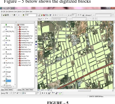
Figure – 5 below shows the digitized blocks
[image:4.612.52.284.361.565.2]FIGURE – 5
[image:4.612.327.561.373.557.2]Figure – 6 below shows features such as tanks and canal that are digitized
International Journal of Emerging Technology and Advanced Engineering
Website: www.ijetae.com (ISSN 2250-2459,ISO 9001:2008 Certified Journal, Volume 3, Issue 5, May 2013)
307 After thus ascertaining the accuracy of the data created, hard copies of the imageries, on scale 1:4,000 were taken, for the purpose of Attribute Data collection from the area. These imageries and plot were taken to the ground and used for picking up major cultural details and their Attribute Data were also collected.
3.4 Queries
Queries are used to match an attribute value to the attribute value in a feature class. Structured Query Language (SQL) is a powerful language you use to define one or more criteria that can consist of attributes, operators, and calculations. With the help of the Data Base thus created, select by Attribute Queries were carried out.
3.5 Quality check
As the imageries used were downloaded from Google Earth, to check the quality/ correctness of the work, 6 Points, well distributed in the area were selected and these were Post Pointed on the Imagery. These points were given coordinates by using
e
Trex H GPS instrument. The results of this check are tabulated below.Table – 1 below shows comparison between GPS and Google earth coordinates.
TABLE – 1
Point No.
Post pointed coordinates
Easting x Northing y
1 243842.183 1926012.489
2 247868.244 1927302.982
3 249386.520 1927886.265
4 247949.026 1924251.205
5 245379.882 1924431.732
6 243151.766 1929618.186
GPS Coordinates Difference between GPS and
Post point coordinates
Easting x Northing y Δx Δy
243843.541 1926011.274 1.358 -1.215
247865.933 1927300.006 -2.311 -2.976
249388.523 1927888.078 2.003 1.813
247950.922 1924252.172 1.896 0.967
245377.890 1924429.251 -1.992 -2.481
243154.080 1929620.364 2.314 2.178
IV. ANALYSIS AND RESULTS
4.1 Proximity Analysis
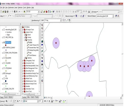
Proximity analysis by Buffer was carried out. To mark no-horn zone around hospitals, buffer zones of 200 meters radius are applied around each hospital. The steps involve
1. In the buffer dialog box, the feature around which buffer zones are required to be applied is chosen i.e. Hospital layer.
2. Thus Buffer zones are formed around each hospital. Figure – 7 below shows the buffer zones.
[image:5.612.315.572.118.338.2] [image:5.612.325.568.451.664.2]International Journal of Emerging Technology and Advanced Engineering
Website: www.ijetae.com (ISSN 2250-2459,ISO 9001:2008 Certified Journal, Volume 3, Issue 5, May 2013)
308 4.2 Network Analysis
Network analysis is the analysis of road or any other network in Arc Map. This analysis usually includes finding the closest facility or service area, new route, alternate routes in case of barriers among many others. Network analysis layers are composite layers in Arc Map used to store inputs, properties, and results of network analyses. A network analysis layer acts as an in-memory workspace for each type of input as well as the result, all of which are stored as in-memory feature classes.
V. CONCLUSIONS
In this project, information has been provided about the extent of land cover, utilities, religious places, and communication network in Boduppal and Pirzadiguda area in the form of a Geographic Information System. Analysis has also been performed in the form of proximity analysis around hospitals, and network analysis for the road network.
This analysis is very useful in setting up of particular zones around point features, to set up check posts, and to estimate the shortest route between two places, etc. This GIS can be used by the public for obtaining basic information about utilities, religious places and educational institutions, and also for route analysis. It can also be used by urban planners alike.
The process of using GIS for urban planning will revolutionize urban land development, which is known to rely on the pen and paper method or obsolete data collection method. It can be concluded that GIS services are very important in mapping and evaluating crucial data that can really contribute to the development of any location. It would be prudent if any public organization were to take note of the immense scope GIS offers and are requested to devise programs that increase the net worth of their city.
REFERENCES
[1] Lefteri, Ilir, Valentina, Majlinda and Fatbardh, Application on GIS for Land use Planning : A Case Study in Central Part of Albania, Research Journal of Agricultural Science, Vol. 41 (2), 2009. [2] W. Drzewiecki, Sustainable Land-Use Planning Support by
GIS-Based Evaluation of Landscape Functions and Potentials - The International Archives of the Photogrammetric, Remote Sensing and Spatial Information Sciences. Vol. XXXVII. Part B7. Beijing 2008. [3] Narimah Samat, Applications of Geographic Information Systems in
Urban, Land Use Planning in Malaysia, The 4th Taipei International Conference on Digital Earth, Taiwan. 25-26 May 2006.
[4] Trevor M. Harris and Gregory A. Elmes The application of GIS in urban and regional planning: a review of the North American experience - Applied Geography (1993)) 13,9-27
[5] Sante Riveira, Rafael Crecente Maseda A review of rural land use planning models Environment and Planning B: Planning and Design 2006, volume 33, pages 165-183 doi:10.1068/b31073"
[6] Florent Joerin, Marius the Riault, Andre Musy - Using GIS and outranking multi criteria analysis for land-use suitability assessment Int. j. geographical information science, 2001, vol. 15, no. 2, 153± 174.
[7] Farkhunda Burke,Syed Nawaz ul Huda, Muhammad Azam, Muhammad Miandad – Application of GIS on Urban Land Use Planning and Revenus Generation - The Research Journal of Sciences and Technology 2(1&2):1-16
[8] S.V. Bobade, B.P. Bhaskar , M.S. Gaikwad, P. Raja, S.S. Gaikwad, S.G. Anantwar, S.V. Patil, S.R. Singh & A.K. Maji - A GIS-based land use suitability assessment in Seoni district, Madhya Pradesh, India - Tropical Ecology 51(1): 41-54, 2010.
[9] Qihao Weng, Land use change analysis in the Zhujiang Delta of China using satellite remote sensing, GIS and stochastic modeling - Journal of Environmental Management (2002) 64, 273–284. [10] E. Taghvaye Salimi, K. Soleimani1, M. Habibnejad Roshan1, K.
Sabetraftar - Land use planning for land management using the geographic information system (GIS) in the Loumir watershed of Guilan province in northern Iran Caspian J. Env. Sci. 2008, Vol. 6 No.2 pp. 141~149