International Journal of Emerging Technology and Advanced Engineering
Website: www.ijetae.com (ISSN 2250-2459, Volume 2, Issue 2, February 2012)280
Performance of Space Time Trellis Code With Rayleigh
Fading Scenario
Sujeet Singh Bhadouria
1, Dr.Manish Shrivastava
2, Kavita Deshmukh
31M.Tech Scholar, Dept. of Information Technology, LNCT, Bhopal, India 2Head, PG Dept. of Information Technology, LNCT, Bhopal, India
3
Ast. professor, PG Dept. of Information Technology, LNCT, Bhopal, India
Abstract— Space Time Trellis codes provided maximum diversity advantage using simple decoding techniques. However, space-time block codes did not provide coding gain, and nonfullrate space-time block codes introduced bandwidth expansion. In this paper we implement space time trellis code using relay fading scenario. We present here the design of the 4psk with 2 transmit antennas and 1,2,4 receiver antennas at 4,8,16&32 state. In this paper we constructed 4-psk STTCs code using rank, determinant and Euclidean distance criterion over Rayleigh fading scenario.
Keywords— space-time-trellis code, multiple transmit antenna, multiple receiver antenna, diversity, wireless communication, fading, s\n ratio.
I. INTRODUCTION
Space-Time-Trellis codes provided maximum diversity advantage using simple decoding techniques. However, space-time block codes did not provide coding gain, and nonfullrate space-time block codes introduced bandwidth expansion. In view of this, it becomes worthwhile to consider a joint design of error control coding, modulation, transmit, and receive diversity to develop an effective signaling scheme called space-time trellis codes (STTC), which is able to combat effects of fading. This concept was first introduced by Tarokh, Seshadri, and Calderbank [6]. It became extremely popular because STTC can simultaneously offer coding gain with spectral efficiency and full diversity over fading channels. This coding gain should not be confused with the coding gain. This coding gain is achieved through the inherent nature of the STTC itself and is distinct from the coding gain achieved by temporal block codes and convolution codes. All A typical S'ITC based wireless system has an encoder, pulse shaper, modulator and multiple transmit antennas at the transmitter, and the receiver has one or more receive antennas, demodulator, channel estimator and STTC decoder. We consider a mobile communication system
with
n
t transmit antennas andn
rreceive antennas asshown in Figures 1 (a) and (b). The space-time trellis
encoder encodes the data
s t
( )
coming from the information source and the encoded data is divided intot
n
streams of data
1 2
...
ntt t t
c
c
c
. Each of these streams of data passes through a pulse shaper before being modulated. The output of modulator
i
at time slott
is the signal i t
c
, which transmitted through is transmit
antenna
i
. Heren
t1
i
n
t. The transmitted symbolshave energy
E
t. We assume that then
tsignals are transmitted simultaneously from the antennas. The signals have transmission period T. In the receiver, each antennareceives a superposition of
n
t transmitted signals corrupted by noise and multipath fading. Let the complex channel coefficient between transmit antenna i andreceive antenna j have a value of
h
i j,( )
t
at timet
,where
1
i
n
r.The received signal at antenna
j j
,
1, 2,...,
n
r G.L. Stuber [1] is then, 1
= ( ) ( )
n
i j
t s i j t t
i
r E h t c t
(1.1)
Where j t
is additive white Gaussian noise (AWGN) at
receive antenna
j
, which has zero mean and powerspectral density
N
0 andh
i j,( )
t
International Journal of Emerging Technology and Advanced Engineering
Website: www.ijetae.com (ISSN 2250-2459, Volume 2, Issue 2, February 2012)281
FIGURE1.A TYPICAL S'ITC BASED WIRELESS SYSTEM
II. CODE CONSTRUCTION OF 4-PSK STTC
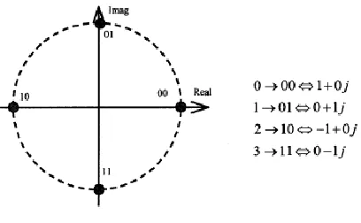
A signal constellation diagram for 4-PSK is shown in Figure 2. With PSK information is contained in the signal phase. For 4-PSK, the phase takes one of four equally
spaced values, such as
2
4
6
0,
,
, and
4
4
4
These are typically represented by a Gray code S. Haykin [10] and B. Sklar [9], as shown on the right side of Figure 2. These signal points are also labeled as 0, 1, 2 and 3. We can also express these in complex notation. The encoder structure of a 4-state 4-PSK STTC is shown in Figure 3 (a), with bits input to the upper and lower branches. The memory orders of the upper and lower
branches are
1and
2 respectively. These are basically shift registers. The main purpose of the shift registers in the encoder is to store the previous transmitted bits. The length of the shift register is the memory of the encoder. The branch coefficients are arranged alternatively in thegenerator matrix, with
a
i representing the mostsignificant bit (MSB). The input bit streams
1 2
and
t t
I
I
are fed into the branches of the encoder with 1 t
I
being the MSB. The output of the encoder is Z. Chen, J. Yuan, B. Vucetic[19], V. Tarokh, N. Seshadri, A. R. Calderbank [6]
1 2
1 2
0 0
.
.
mod 4
1, 2,
v v
k k k
t t p p t q t q
p q
x
I
a
I
b
k
(1.2)where
v
1
v
2
v
and the number of states is2
v.v
i is calculated as1
,
1, 2
2
i
v i
v
i
(1.3)Here
x
denotes the largest integer smaller than or equal tox
. For each branch, the output is the sum of the current input scaled by a coefficient and the previous input scaled by another coefficient. The two streams of input bits are passed through their respective shift register branches and multiplied by the coefficient pairs1 2 1 2
(
a
p,
a
p) and ( ,
b
qb
q)
. Here,
1 2,
0,1, 2,3 ,
1, 2,
0,1,...., ,
0,1,...., .
k k p q
a b
k
p
v q
v
[image:2.612.337.541.487.613.2]International Journal of Emerging Technology and Advanced Engineering
Website: www.ijetae.com (ISSN 2250-2459, Volume 2, Issue 2, February 2012)282
(A)
(B)
FIGURE3.4PSK4 STATE STTC(A)TRELLIS DIAGRAM (B)ENCODER STRUCTURE
Then
1 2
and
t t
x
x
are transmitted simultaneous through the first and second transmit antennas, respectively. Figures 4 (a) and (b) shows 8 state and 16 state trellis diagrams respectively, for a rate of 2 b/s/Hz N. Seshadri, V. Tarokh, A.R. Calderbank [3].
FIGURE4.(A)TRELLIS DIAGRAM OF 4-PSK8STATE STTC
FIGURE4.(B)TRELLIS DIAGRAM OF 4-PSK16STATE STTC
III. PERFORMANCE CRITERIA
We assume that the STTC codeword is given by
1 2 1 2 1 2
1 1 1 2 2 2
(
....
nt...
nt...
....
nt)
l l l
c
c c
c c c
c
c c
c
Where
l
is the frame length. We consider a maximum likelihood receiver, which may possibly decide on an erroneous code word e , given by1 2 1 2 1 2
1 1 1 2 2 2
(
....
nt...
nt...
....
nt)
l l l
e
e e
e e e
e
e e
e
We can write the difference code matrix, the difference between the erroneous codeword and the transmitted codeword as follows –
1 1 1 1 1 1
1 1 2 2
2 2 2 2 2 2
1 1 2 2
3 3 3 3 3 3
1 1 2 2
1 1 2 2
...
...
...
( , )
.
.
...
.
.
.
...
.
.
.
...
.
...
t t t t t t
l l
l l
l l
n n n n n n
l l
e
c
e
c
e
c
e
c
e
c
e
c
e
c
e
c
e
c
B c e
e
c
e
c
e
c
International Journal of Emerging Technology and Advanced Engineering
Website: www.ijetae.com (ISSN 2250-2459, Volume 2, Issue 2, February 2012)283
The difference matrix
B c e
( , )
has dimensionn
t
l
. From N. Seshadri, V. Tarokh, A.R. Calderbank [9] weknow that to achieve the maximum diversity order
n
r,n
t(
n
r, receive antennas,n
t transmit antennas) matrix( , )
B c e
must have full rank for all possible codewords cand e . If
B c e
( , )
has minimum rank r over the set ofpairs of distinct codewords then the diversity will be
r n
.
r N. Seshadri, V. Tarokh, A.R. Calderbank [3].IV. DESIGN CRITERIA FOR STTC OVER RAYLEIGH FADING
A. Rank Criterion
The rank criterion optimizes the spatial diversity gain achieved by a STTC. Assume B(c,e) has minimum rank
r
over the set of pairs of distinct codewords so adiversity of
r n
.
ris acheved V. Tarokh, N. Seshadri, A. R. Calderbank [6], Z. Chen, J. Yuan, B. Vucetic [8]. To illustrate this criterion N. Yuen [5], consider a CPSK system where the transmitted codeword is c = 220313, and the erroneous codeword the receiver decides upon is e = 330122. Figure 2 gives the 4PSK signal constellation.In this example,
n
t= 2 and the message length is L = 3.The
2 3
difference matrix is( 1)
1 1
1
( , )
( 1)
(
)
1 (
)
j
j
B c e
j
j
j
j
The rank of B(c,e) is 2, as is the rank of A(c,e) . For
this system with
n
t= 2 transmit antennas andn
r= 1 receive antenna, the diversity gain is 2.B. Determinant Criterion
The determinant criterion optimizes the coding gain.
Recall that
r
is the rank ofA c e
( , )
. Coding gain corresponds to the minimumr
th roots of the sum of the determinants of allr r
principal cofactors of*
( , )
( , )
( , )
A c e
B c e B c e
taken over all pairs ofdistinct codewords
c
ande
V. Tarokh, N. Seshadri, A.R. Calderbank [6]. Now
(
1 2 3... )
r is the absolute value of the sum of the determinants of all principalr r
cofactors of A.Thus if a diversity advantage of
n r
r is achieved, thecoding gain is
1 1 2 3
(
... )
rr
. So if maximum
diversity of
n n
r t is the design target then we have tomaximize the minimum determinant of
A c e
( , )
. From the example, for the rank criterion the eigenvalues of the matrix A are1
2
2.2679 3 5.7321 3
j j
For r = 2, the coding gain for the codeword given in the example is 4.9327 N. Yuen [5].
Euclidean distance Criterion
When the diversity gain is large (with two or more receive antennas), Chen, B. Vucetic, J. Yuan and Lo. Ka. Leong [2] proposes another design criterion, namely the Euclidean Distance Criteria (EDC). According to Chen, B. Vucetic, J. Yuan and Lo. Ka. Leong [2], the Rank and Determinant criteria (RDC) applies to the systems with a single receive antenna and a small number of transmit
antennas. This shows that with diversity gain
rn
r
4
S. M. Alamouti [12] shows that the error probability is upper bounded by1 1 0
1
( ) exp
4 4
t
n l
i i s
e r j j
i j
E
P c e n e c
N
(3.13)
When
rn
r
4
, Which indicates that we should maximize the minimum squared Euclidean distance between any two different codewords Chen, B. Vucetic, J. Yuan and Lo. Ka. Leong [2] .V. SIMULATION SYSTEM MODEL
The simulation is carried out in MATLAB. The simulation system model is illustrated in Figure 5.
International Journal of Emerging Technology and Advanced Engineering
Website: www.ijetae.com (ISSN 2250-2459, Volume 2, Issue 2, February 2012)284
Random M-PSK symbols are grouped into frames, which consists of 130 symbols each. The space-time encoder takes the frame as input and generates codeword pairs for each input symbol simultaneously for all the transmit antennas. Pulse shaping and matched filter are used for simulation over frequency selective fading channels.
These complex signals are transmitted through the MIMO channel. The signals and channels are modeled in base-band, thus modulation/demodulation operations are not carried out. Channels used in this project include flat Rayleigh fading channels and two-ray model frequency selective fading channel.
We assume that perfect channel state information (CSI) is available at the receiver. At the receiver, a maximum likelihood sequence detector is used to decode the received signal. A modified vector Viterbi decoder is employed. Error probability calculation is carried out after decoding each frame.
VI. SIMULATION RESULT OVERRAYLEIGH FADING CHANNEL
TABLE 1.NEW 4-PSK2-XTR TRELLIS CODES PROPOSED BY CHEN ET AL.
0 2 4 6 8 10 12 14
10-2 10-1 100
SNR
F
E
R
f
ra
m
e
e
rr
o
r
ra
te
4 state 8 state 16 state 32 state
FIGURE 6. 4PSK,2 TRANSMITTER,1 RECEIVER
0 2 4 6 8 10 12 14 10-4
10-3 10-2 10-1 100
SNR
F
E
R
f
r
a
m
e
e
r
r
o
r
r
a
t
e
4 state 8 state 16 state 32 state
FIGURE 7. 4PSK,2 TRANSMITTERS,2 RECEIVER
states a01,
a02
a11,
a12
a21,
a22 a31
,a32 b01
,b02 b11,
b12 b21
,b22 b31
,b32 4 (0,2) (1,2) - - (2,3) (2,0) - -
8 (2,2) (2,1) - - (2,0) (1,2) (0,2) -
16 (1,2) (1,3) (3,2) - (2,0) (2,2) (2,0) -
32 (0,2) (3,1) (3,3) (3,2 )
International Journal of Emerging Technology and Advanced Engineering
Website: www.ijetae.com (ISSN 2250-2459, Volume 2, Issue 2, February 2012)285
0 2 4 6 8 10 12 14
10-4 10-3 10-2 10-1 100
SNR
F
E
R
f
r
a
m
e
e
r
r
o
r
r
a
t
e
4 state 8 state 16 state 32 state
FIGURE 8. 4PSK,2 TRANSMITTERS,4 RECEIVER
VII. CONCLUSION
In this paper, an efficient method to design the best 4-psk STTCs with two transmit antennas and 1,2,4 receiver antennas has been presented. we find that when we increase the receiver antennas .we get more coding gain .it increase 4to32states.we find higher coding gain at 2 receiver antennas at 32 state in fig. 7. We also get less s\n ratio and also in fig.6,fig.7.
References
[1] J. Yuan, 2. Chen and B. Vucetic, " Performance of space-time c o h g on fading channels," IEEE Trans. Commn , vol. 51, no. 12, pp. 1991-1996, Dec. 2003.
[2] J. Lai and N. B. Mandayam, “Performance of turbo coded WCDMA with downlink space-time block coding in correlated fading channels," accepted for publication in IEEE transaction on wireless communications,2002.
[3] N. Seshadri, V. Tarokh, A.R. Calderbank," Space-time codes for wireless communication: code construction," IEEE 47th Vehic. Tech.. Conf. Tech.., pp. 637-641, 1997.
[4] Z. Chen, J. Yuan, B. Vucetic, "Improved space-time trellis coded modulation scheme on slow Rayleigh fading channels," Ehctronics Lett., vo1.37, pp.440-441,29 Mar. 2001
[5] N. Yuen, " Performance Analysis of Space-time Trellis codes," Master of Engineering report, University of British Columbia, April 2000
[6] V. Tarokh, N. Seshadri, A. R. Calderbank, "Space-time codes for high data rate wireless communication: performance criterion and code construction," IEEE Trans. Innfom. Theoy, vol.44, pp. 744-65, Mar. 1998.
[7] G. Foschini, “Layered space-time architecture for wireless communication in a fading environment when using multi-element antennas," in Bell Labs Technical Journal, 1996, pp. 41-59.
[8] Z. Chen, J. Yuan, B. Vucetic, "Improved space-time trellis coded modulation scheme on slow Rayleigh fading channels," Ehctronics Lett., vo1.37, pp.440-441,29 Mar. 2001.
[9] H. Shah, A. Hedayat, and A. Nosratinia, “Performance of concatenated channel codes and orthogonal space-time block codes," submitted to IEEE Transactions on Wireless Communications, 2003.
[10]S. Haykin, Communication Systems. Delhi, India, John Wily and Sons, 4& edition, 2001
[11]J. Yuan, 2. Chen and B. Vucetic, " Performance of space-time c o h g on fading channels," IEEE Trans. Commn , vol. 51, no. 12, pp. 1991-1996, Dec. 2003.