Journal of Chemical and Pharmaceutical Research, 2014, 6(7):1523-1530
Research Article
CODEN(USA) : JCPRC5
ISSN : 0975-7384
Gap element method of longitudinal vibration of drill string
Liu Weikai
#, Song Mingxing
*, Xu Ziyi
@and Zhang Xuehong
##
Petroleum Engineering College, Northeast Petroleum University, Heilongjiang Daqing, China
*Daqing drilling engineering institute of technology, Heilongjiang Daqing, China
@School of Petroleum Engineering, China University of Petroleum, Beijing Campus, Beijing, China
_____________________________________________________________________________________________ABSTRACT
Due to the lower tool as the research object to analyze the vibration of the drill string, causes the loss of the low order natural frequency of the drill string and the inherent vibration mode, give rise to the distortion and error of the result from the transient analysis of the drill string. For this purpose, the whole drill string of the deep wells is studied in the article, build the mechanical model of axial vibration for the deep wells. Analyze and calculate the dynamic response of the drill string by adopting the method of three-dimensional dynamic finite element theory improved the Ritz vector method at the same time, present the fatigue limit stress formula of the drill string, and the software has been compiled based on the above model and the theory. Convenient for drilling construction, contemporary, give the effective action of the vibration reduction based on the theory and calculation.
Keywords: Drill string; Vibration; Gap Element; Fatigue; Vibration Reduction;
_____________________________________________________________________________________________
INTRODUCTION
In the drilling operation, the failure the drill string often occurs, and destructive, so we should avoid the drill string failure actively. Fatigue fracture failure is the main failure mode of the drill string, the fatigue fracture failure of the drill string includes three basic types: The first is the pure fatigue failure; the second is scars of fatigue failure; the third is corrosion fatigue damage. These damage and the drill string vibration have a direct relationship, especially with the longitudinal vibration of the drill string. The fatigue failure the drill string is mainly caused by the longitudinal vibration of the drill string, Due to limited by borehole diameter smaller, transverse vibration will not be huge [1-3], so the influence of drill string fatigue will be secondary. The influence of the torsional vibration of drill string fatigue is secondary too, for this purpose, this paper mainly studies the longitudinal vibration of drill string.
Fig. 1 Divided sketch map of drill string fabric cell
1 METHOD AND THEORETICAL EQUATION
1.1 MECHANICAL MODEL OF THE DRILL STRING LONGITUDINAL VIBRATION ANALYSIS
The mechanical model is based on the overall drill string in this article, this is, the whole drill string from the wellhead to the bottom as research subjects, it can be any combination of the drill collars, drill pipe, joints, stabilizer and shock absorbers and other various parts of the drill. Taking into account the influence of the surface structure on the drill string vibrations, The derrick, wire rope and the traveling block and the other structure on the ground are simplified to the equivalent structure which the axis free, but the transverse immobile, As shown in Figure 1.
The actual borehole of the deep wells is not an ideal straight line, but an arbitrary curved three-dimensional space curve. So it is reasonable to consider the drill string as the three-dimensional which is coincided with the borehole axis. At the same time, should consider the impact on the drill string fatigue strength of the drill string bending stress caused by the initial curvature.
In the process of drilling, drilling bit beat in the bottom hole. Impose a longitudinal vibration force on the bottom of the drill string. The vibration force can approximate as a simple harmonic vibration force.
P=P0sin(ωt) (1)
In the formula,
P
0is the excitation force amplitude.ω
is Circular frequency of excitation force. t is time variable.1.2THE FINITE ELEMENT EQUATIONS OF THE DEEP WELL DRILL STRING LONGITUDINAL VIBRATION
Discrete deep well drilling string along the axis into several space straight beam element. Using dynamic finite element method to vibration analysis .Get the longitudinal vibration equation of whole drill string structure are as follows:
( )
0t
0
sin
ω
P
=
KU
+
U
C
+
U
M
&
&
&
(2)The M, C and K in the formula is he overall quality of the whole drill string matrix, damping matrix and stiffness matrix respectively.
U
&
&
,U
&
,U
is node acceleration vector, the velocity vector and displacement vector respectively.P
0 is the excitation amplitude vector.ω
0 is the longitudinal excitation frequency at bit. Using the method of modal superposition addition to solve the equation (2).The first thing is to determine inherent vibration mode and natural frequency of the drill string. We should solve the undamped free vibration equation at first:0
=
+
KU
U
M
&
&
(3)Assuming the form of the solution is[3]
)
sin( t
ω
Φ
U
=
(4)According to this equation, the frequency equation is:
K -
ω
2M = 0
(5)natural frequency.
n
ω
ω
ω
ω
〈
〈
L
〈
3 2
1 (6)
Further, we can use the improved Ritz vector method to solve the n inherent vibration mode corresponding to the n natural frequency
Φ
i(i=1, 2,…,n).1.3 THE MODAL SUPERPOSITION METHOD OF THE DEEP WELL DRILLING TOOL DYNAMICS ANALYSIS.
Express the corresponding displacement of drill string with the linear combination of the first order natural vibration mode:
[
]
Φ
y
U
m 21 2 1 2 2 1 1 m m m m m
y
y
y
y
y
y
=
=
+
+
+
=
M
L
L
φ
φ
φ
φ
φ
φ
(7))
,
,
2
,
1
(
i
m
y
i=
L
is the generalized coordinates related to the damping. Substituting this formula into formula(2), and we can solve the m independent second order nonhomogeneous linear differential equations.
)
,
,
2
,
1
(
)
sin(
2
y
2y
P
* 0t
j
m
y
&
j j j&
j j j jL
&
+
ω
γ
+
ω
=
ω
=
(8)
In this formula,
P
*=
Φ
TP
.The Special solution of the last-written is;)
os(
)
in(
0t
B
c
0t
s
A
y
j=
jω
+
jω
(9) In this formula:
(
j
m
)
P
B
P
A
j j j j j j j j j j j j j j j,
,
2
,
1
2
1
2
2
1
1
2 0 2 2 2 0 0 2 * 2 0 2 2 2 0 2 2 0 2 *L
=
+
−
−
=
+
−
−
=
ω
ω
γ
ω
ω
ω
ω
γ
ω
ω
ω
γ
ω
ω
ω
ω
ω
(10)Thus , in response to displacement of the drill string is;
)
cos(
)
sin(
0t
0t
m
Φ
A
ω
Φ
B
ω
U
=
+
(11)Accordingly, the response can be further calculated forces and stress response, as drill string dynamic strength assessment basis
1.4 DAMPING CALCULATION DRILL STRING
Drill string in contact with the wall friction was not much, but it is generally different damping mud. Rayleigh damping used here, assuming that the damping matrix;
2
1
C
C
C
=
+
(12)K
M
C
1=
α
+
β
(13)Right side of equation coefficients α, β is an arbitrary scale factor, the overall mass matrix, stiffness matrix structure of the drill string.
It can be seen from this formula is a linear damping mode, which is the ratio of the two mass and structural stiffness and structural damping associated linear combination. The former considers only the inside of the structural material damping , ignoring the viscous fluid damping structure surrounding the object ; which only consider the viscous damping fluid , a damping structure is ignored within the material . In theory, the general model of single- proportional damping unreasonable, the result is not entirely realistic, reasonable combination of the two linear damping formula (2-2).
t 2
U
=
R
C
&
(14)Where Rt represents the contact friction vector, each element of which represents the frictional resistance on the
corresponding node, the drill string static analysis results, and then converted to an equivalent diagonal damping matrix based on the node speed. So then according to formula (3-25) to obtain the total damping matrix
2. DRILL STRING FATIGUE STRENGTH ANALYSIS THEORY 2.1 DRILL STRING PRELOAD STRESS
For different types of drill collars and drill pipe, which the buckle tightening torque is different, there are norms to be investigated. But actually buckle tightening torque requirements and specifications buckle tightening torque on the site of operation is different , in fact deducted in the calculation applied tightening torque . In the role of the buckle tightening torque, tensile stress is generated in the vicinity preload stress slots and threaded root public deductible approximated as:
fRA
M
2
0 y
=
σ
(15)Where is the buckle tightening torque, it drill collars, drill pipe type and buckle type related; to face contact drill collars and drill pipe friction coefficient; was threaded root diameter; sectional area of threaded root. Here trapezoidal thread ignores the impact angle of inclination of the tooth face, because the tilt angle trapezoidal thread tooth face is very small, its impact is negligible。
2.2 WORK DRILL STRING STATIC STRESS
In the mean weight WOB and the role of the cross-section of the drill string will produce a positive tension and compression stress, which is calculated as:
A
N
J P=
σ
(16)Where in the static axial force, the cross-sectional area of the drill string, if the threaded joint is effective when the cross-sectional area。
2.3 DRILL STRING NORMAL STRESS AMPLITUDE LONGITUDINAL VIBRATIONS
Vibration analysis by the drill column can be harmonic alternating vertical drill string vibration amplitude axial force D, whereby the drill string can be calculated longitudinal vibration amplitude of normal stress:
A
N
D=
l
σ
(17)This stress is a major factor in fatigue failure caused by the drill string.
2.4 INITIAL DRILL STRING BENDING NORMAL STRESS Wellbore curvature caused by the initial drill string bending stresses as
σ
ρ
0
2
Where is the radius of curvature of the wellbore, the outer diameter of the drill string, the drill string is elastic modulus. The initial drill string bending stresses are stresses in the turntable drilling is alternating, belonging to dynamic stress; directional drilling when it is a positive constant stress, are static stress. For straight-deep well, the initial bending stresses in the drill string is very small and negligible.
2.5 CALCULATE THE CROSS SECTION OF THE DRILL STRING STRESS
Cross-section of the drill string stress can be divided into two parts: First, the average stress, and second alternating stress amplitude. If using a power drill, power drill should also consider the impact of rotation.
Turntable does not turn, turn turbo drill Besides turntable turbo drill turn
+
=
+
=
=
+
+
=
0 1 a P y m
1 a 0 P y m
,
,
T
λσ
σ
σ
σ
σ
σ
σ
σ
σ
σ
σ
σ
(19)
Where the ratio of the rotation frequency and the frequency of the exciting force drill turntable。
2.6 DRILL STRING FATIGUE STRENGTH CONDITIONS
Drill string at work, stress at each cross-section of a typical asymmetric cycle state, in a cycle characteristics r, promised a cross-section of the drill string with fatigue (lasting) limit is calculated using the following formula[12];
[ ]
[ ][ ]
(
)
[ ]
(
)
[ ]
σ
σ σ
σ
σ
r
r
r
=
−
+ ++ +
− −2
1
1
1 1
1 1
(20)
a m
a m
σ
σ
σ
σ
+
−
=
r
(21)The r in the formula is characteristic value of asymmetrical stress cycling.
[ ]
σ
+1 is the allowable stress of (static) constant load , which is related to the material yield limit of the drill stringσ
sand static load safety factorn
s.[ ]
σ
−1 is the drill string in the symmetry of allowable stress cycle conditions endurance limit , which is related to thestress concentration factor of the drill string
β
, the size coefficientε
d and the coefficient of surface processingh
ε
. Considering the above several kinds of factors, which affect the endurance limit, the drill string in the symmetry of allowable stress cycle conditions endurance limit is[ ]
1d h d
1 −
−
=
ε
ε
β
σ
σ
n
(22)The
n
d in the formula is the dynamic basic safety coefficient ,σ
−1 is the drill string material tensile compression endurance limit , which is related to the string material strength limitσ
b and the yield limitσ
s, it can be expressed by(
s b)
10
.
27
σ
σ
σ
−=
+
(23)[ ]
σ
rσ
σ
σ
max=
m+
a≤
(24)The
ω
max is the biggest working allowance strength of the drill string. If only just one which don’t be content with the fatigue strength condition formula (24), the drill string is taken for which can produce fatigue fracture, so the drill string fatigue safety assessment is on the basis of the formula (24).For the whole drill string , cross section at different positions of well depth, working stress, the stress cycle characteristic values are also different , the allowable endurance limit
[ ]
σ
r is also different , owing to ther
and[ ]
σ
r is related to the stress of the cross section size . So the whole drill string each section of the working stress and allowable endurance limit is different, all need calculated one by one, and then check intensity of each section whether meet the conditions, combine to give the whole drill string fatigue safety assessment conclusion.RESULTS AND DISCUSSION
3.1 EXAMPLE
According to S - 7 Wells of real drilling, engineering design and application of the above theory and the corresponding software of the shaft of the drill string longitudinal vibration and fatigue strength is analyzed and forecast and evaluation . This well deepest depth is 3880m , the density of the mud is 1.14-1.270 g/cm3 , the material of the drill pipe is
σ
s= 773MPa,b
σ
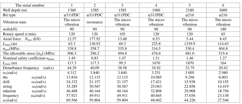
=879MPa . The calculation results are shown in table 1.Can be seen from Table 1 with the gradual deepening of the drilling and the drilling string lengthen, the natural frequencies of the drill string in decreases, and when the excitation frequency of drill string and a natural frequency phase recently, the drill string will be violent vibration. Excitation frequency resonance region will be from the fifth (the fourth natural frequency and natural frequency between 5) into the sixth new non-resonant area (natural frequency in the fifth and sixth) between natural frequency. Along with the further deepening of drilling footage, excitation frequency will also from the sixth non-resonant area into the seventh non-resonant area, meanwhile to skip the sixth resonance region . Instances of penetration gradually close to 1585 m, the vibration of the drill string has a tendency to increase. In the depth of 1585 m, the rotary speed of 120 r/min, the excitation frequency of drill string for omega p = 40.09 rad/s, obviously the excitation frequency and the fifth order natural frequency (40.164) is very close, so the intense vibration or resonance happens . The maximum axial force is very big, is 177.92kN, occurred in the bit of 130.8 m. Drill string fatigue dangerous section develops at the site of about 117.3 m from the bit, the cross section of the maximum dynamic stress σmax = 358.7 MPa, the name of the safety coefficient is 0.83,
[image:6.595.66.550.544.753.2]less than 1, is likely to have the occurrence of fatigue fracture failure. To avoid the resonance, need to change the rotary speed to adjust the bit the excitation frequency, excitation frequency and the fifth order natural frequency stagger, won't appear resonance phenomenon. For this table and another is given rotary speed 105 r/min, the scheme, the scheme can avoid the drill string in Ci-Jing deep resonance.
Table 1 Result of evaluation and forecast of lengthwise vibration respond fatigue intensity of S-7 well whole drill string
The serial number 1 2 3 4 5 6
Well depth (m) 1360 1585 1585 1960 2160 3600 Bit type φ311PDC φ311PDC φ311PDC φ311PDC φ216 φ216 Vibration state The micro
vibration resonance
The micro vibration
The micro vibration
The micro vibration
The micro vibration
wob(kN) 90 90 90 90 90 180
Rotary speed (r/min) 120 120 105 120 120 65 Axial force Nmax (kN) 12.57 177.92 13.68 6.53 5.44 8.45
Lnmax (m) 63.3 130.92 69.3 225.8 1339.9 114.63
σmax(MPa) 338.8 358.7 335.8 316.5 330.4 404.8 The allowable stress [σpl] (MPa) 506.3 296.2 494.0 476.6 481.0 515.6 Nominal safety coefficient nplmin 1.49 0.83 1.47 1.51 1.46 1.27
Lnmin (m) 117.3 117.3 99.3 1670 1870 164 Disturbance frequency (rad/s) 44.29 40.09 38.58 34.92 32.79 20.42
ω1(rad/s)
the ω2(rad/s) drill ω3(rad/s) string ω4(rad/s) inherent ω5(rad/s) frequency ω6(rad/s)
ω7(rad/s)
4.312 13.816 24.332 35.285 46.488 57.921 69.566
3.840 12.115 21.157 30.567 40.164 49.911 59.804
3.840 12.115 21.157 30.567 40.164 49.911 59.804
3.251 10.085 17.421 25.043 32.808 40.665 48.602
3.005 9.296 15.938 22.858 29.908 37.036 44.226
Notion: LNman(m) and Lnmin (m) in the table are respectively presented the distance which is from the drill string maximum axial force Nmax (kN) to the bit of distance and fatigue in the dangerous section to the distance of the drill bit ; σmax(MPa) and [σpl](MPa) are respectively presented the fatigue dangerous section in the maximum working stress and allowable stress fatigue
3.2 ANALYSIS OF VIBRATION REDUCTION MEASURES
(1) Change the speed of the drill string. As before, when the violent vibration of the drill string, the changing speed of vibration reduction is one of the most simple and effective measures. Speed change will change the bit the excitation frequency, will not change the natural frequency of the drill string. The effect which is very close to the excitation frequency and inherent frequency staggered, to achieve the purpose of reducing vibration. Change can be reduce the speed, rotational speed can be increased speed, reduction should not be too big, so as to avoid vibration resonance region from the current to the adjacent another resonance zone, the ideal of the frequency of the exciting force should be a fall in between the two resonance region near the resonance zone of intermediate value, damping effect is best.
(2) Increase the weight on bit. When the violent vibration of the drill string, if the weight is not too big, the appropriate increase the weight on bit to vibration also to have certain advantages, but time is too long. Appropriate increase the weight on bit can reduce bit bounce, can achieve the purpose of reducing vibration.
(3) Change the drill bit. The violent vibration of the drill string, sometimes is a bit of broken teeth. Especially cone bit off after the tooth, the rotation is not very smooth, beating a lot and penetration is very small, long drill grinding beating, will cause the drill string fatigue fracture. Appear this kind of circumstance must be timely replacement of bit, the driller with rich experience in drilling is required to timely detection and timely replacement.
(4) Change the tool. The violent vibration of the drill string, the first to think of drilling tool structure is reasonable, if too little drill collar should be appropriately increased the number of drill collar, upper drill collar to put heavier drill pipe at the same time.
CONCLUSION
In the longitudinal vibration of the drill string fatigue strength assessment and prediction of available the following understanding:
(1) Establish the deep well drilling string mechanical model of longitudinal vibration analysis and the theory of finite element analysis method is correct and effective.
(2) Of the drill string fatigue limit stress calculation formula, right of drill string fatigue strength provides theory basis for quantitative evaluation and prediction.
(3) Change in drilling construction speed of vibration reduction is one of the most simple and effective measures, but the speed increase or decrease amplitude should not be too big, in order to avoid the resonance of vibration from the current area to another, the resonance zone adjacent to create new resonance.
(4) The drill string vibration in the borehole mud, its damping is bigger. How to accurately select damping coefficient, on the drill string vibration is also very important, need to be further in-depth study.
Acknowledgments
Project supported by Heilongjiang Postdoctoral Research Startup of China (Contract No. LBH-Q13038) and Heilongjiang Province Education Department (Contract No. 12541099).
REFERENCES
[1] JK Vandiver, et al. SPE 16660 [2] MB Allen. SPE/LADC 16110 [3] DA Close, et al. LADC/SPE 17273
[4] I Finnie, JJ Bailey. J. of Engr. For Industry, May 1960 [5] JJ Bailey, I Finnie. J. of Engr. For Industry, May 1960
[6] DW Dareing, BH Livesay. Petroleum Mechanical Engineering and First Pressure Vessel and Piping Conference, Dallas, TX, Sept. 1968
[7]YL Zhang. Oil Field Equipment,1988(2):1~6
[8] JK Vandiver, et al. Oil Field Equipment,2001(4):60~69
[9] Q zhan, DT Liu. Petroleum machinery,1996,24(2):54~57
[11] SH Mu etc. Journal of oil,1992(1):108~117