R E S E A R C H
Open Access
Automatic lumen segmentation in IVOCT images
using binary morphological reconstruction
Matheus Cardoso Moraes
*, Diego Armando Cardona Cardenas and Sérgio Shiguemi Furuie
* Correspondence:
[email protected] Department of Telecommunication and Control, School of Engineering of the University of São Paulo, Av. Prof. Luciano Gualberto, Travessa 3, 158 - sala D2-06, São Paulo, SP CEP 05508-970, Brazil
Abstract
Background:Atherosclerosis causes millions of deaths, annually yielding billions in expenses round the world. Intravascular Optical Coherence Tomography (IVOCT) is a medical imaging modality, which displays high resolution images of coronary cross-section. Nonetheless, quantitative information can only be obtained with segmentation; consequently, more adequate diagnostics, therapies and interventions can be provided. Since it is a relatively new modality, many different segmentation methods, available in the literature for other modalities, could be successfully applied to IVOCT images, improving accuracies and uses.
Method:An automatic lumen segmentation approach, based on Wavelet Transform
and Mathematical Morphology, is presented. The methodology is divided into three main parts. First, the preprocessing stage attenuates and enhances undesirable and important information, respectively. Second, in the feature extraction block, wavelet is associated with an adapted version of Otsu threshold; hence, tissue information is discriminated and binarized. Finally, binary morphological reconstruction improves the binary information and constructs the binary lumen object.
Results:The evaluation was carried out by segmenting 290 challenging images
from human and pig coronaries, and rabbit iliac arteries; the outcomes were compared with the gold standards made by experts. The resultant accuracy was obtained: True Positive (%) = 99.29 ± 2.96, False Positive (%) = 3.69 ± 2.88, False Negative (%) = 0.71 ± 2.96, Max False Positive Distance (mm) = 0.1 ± 0.07, Max False Negative Distance (mm) = 0.06 ± 0.1.
Conclusions:In conclusion, by segmenting a number of IVOCT images with
various features, the proposed technique showed to be robust and more accurate than published studies; in addition, the method is completely automatic, providing a new tool for IVOCT segmentation.
Keywords:Intravascular optical coherence tomography (IVOCT), (IOCT), Coronary
disease, Segmentation, Wavelet, Otsu, Mathematical morphology
Background
Cardiovascular disease (CVD) is the number one cause of death in the United States (USA). According to the American Heart Association [1], in 2007 a rate over 2200 people lost their lives by CVD every day. It corresponded to 33.6%, more than 1/3 of all deaths. Consequently, CVD had also the greatest cost among all diseases, U$286 billion. Among CVDs, the coronary diseases are the most common, and they led to approximately 407,000 deaths in 2007, half of the CVD mortalities [1]. On account of
this striking problem, equipment, tools and methods, which could lead to better diag-nostic, therapies, and interventional procedure, have been attracting an enormous research interest. Consequently, the use of Intravascular medical imaging modalities, such as Intravascular Ultrasound (IVUS) and Optical Coherence Tomography (IVOCT) have become essential tools in cardiologic centers [2-5].
IVUS and IVOCT are invasive medical imaging modalities based on ultrasound and near-infrared technologies, respectively. In both modalities, image acquisition is carried out by inserting the specific catheter inside the artery and performing a pullback movement. Accordingly, cross-section images with anatomical, morphological and pathological information of arteries are provided [2,3,5,6]. As a result, more reliable diagnostic are obtained, and correct therapeutic procedure may be executed [4,7-9]. Nonetheless, only images do not supply the cardiologist with objective information, such as plaque, lumen, and elastic-lamina perimeter, radius, diameter, size, etc. [10-12]. Therefore, accurately separating related objects in an image bring special information for a range of coronary investigation; consequently, segmentation has been the scope of many studies recently [2-4,6,7,9,13].
Segmentation is a procedure in which related structures are recognized and deli-neated in an image, hence separating wanted object from the rest of the image [11,14]. Recognized as one of the hardest and most significant imaging processing operations, segmentation is directly or indirectly part of the great majority of imaging processing algorithm [11,15,16]. It can be executed manually by a skilled operator; semi-automa-tically, initialized by seed or contour and completed by an algorithm; and completely automatic, where the images are selected, and a method is applied for the entire process [17]. The implication is that, objective information of perimeter, radius, diameter, size of plaque, lumen, and elastic-lamina are supplied [11,12]. Specifically, it is important for a range of coronary investigations, for instance, quantification of stenosis, and its regression during treatment, following in-stent neointimal re-stenosis [18], and for a 3D reconstruction. As a result, diagnostic, therapy planning, treatment, evaluations, and interventional procedure are much more reliably and efficiently executed [4,11,12,19-23].
The approaches described in the literature have used advanced and modern metho-dologies, and presented good results. Nonetheless, two main drawbacks can be found in most solutions. First, they are computationally demanding, due to computationally heavy operations, such as training stage. Second, they are semi-automatic, since IVUS and IVOCT are modalities that provide hundreds and even thousands of images per exam; manual, and even semi-automatic segmentation methods become a stressful and time-consuming task. In addition, they may have high variability among operators due to different initializations. Therefore, automatic segmentation methods are a more adequate and practical tool for both modalities [32,33,41]. In addition, since IVUS is older than IVOCT, engineers can find from the literature a much wider variety of methods for enhancing, or implementing solutions to create extra tools or to embed in new IVUS equipment. In order to provide this variety of methods for IVOCT as well, alternative approaches should be created, and/or successful IVUS segmentation methods, adapted and migrated to IVOCT. Therefore, a successfully applied IVUS segmentation Method, presented in [32,38], has been adequately adapted, and a new, computationally light, and fully-automatic lumen segmentation method for IVOCT images was created. A previous and concise version of this IVOCT approach was first introduced and presented in [39].
Materials and methods
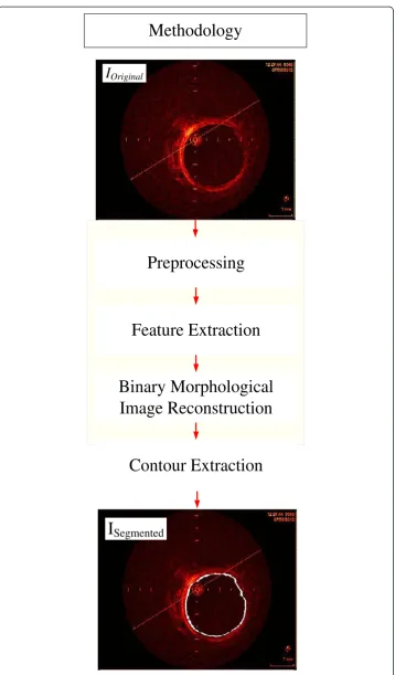
The segmentation methodology is based on combining operations in three steps, Prepro-cessing, Feature Extraction and Binary Morphological Image Reconstruction (Figure 1). The evaluation was performed comparing the segmented images with their gold standards made by experts and calculating the parameters of accuracy [15,32]. The material is composed by a set of 290 IVOCT images from 2 patients, 2 pigs, and 1 rabbit, from the database of the Heart Institute of the University of São Paulo Clinic Hospital, Brazil (InCor). The 290 images in the dataset were chosen to represent a variety of coronary feature in IVOCT images, such as different degree of wall contrast, lumen irregularities due to thrombus, plaques and branches, and with 30 and 180 days after stent implantation, the study protocol was approved by the ethic committee of InCor with informed consent signed by patients. The images were acquired with pullback of 0.5 mm/s, and 20 f/s, by a TD-OCT, St. Jude/LightLab ImageWire catheter, connected to the St. Jude/LightLab OCT Imaging System and Probe Interface Unit (St. Jude/LightLab Optical Coherence Tomography – St. Jude Medical, Inc., Westford, Massachusetts, USA).
Preprocessing
I
OriginalI
SegmentedPreprocessing
Feature Extraction
Binary Morphological
Image Reconstruction
Methodology
Contour Extraction
and the alignment mark are undesirable features for this purpose, and may damage and limit the segmentation procedure. On the contrary, work with circular structures, such as coronary, in the polar domain has many advantages due to its 1D appearance [4].
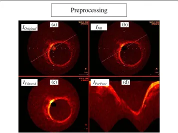
The catheter reflection, and the alignment marks are recognized by a ring at the center of the IVOCT image, and straight lines marking fixed positions, and one long line crossing the image (Figure 2a). For our purpose, they can be seen as noise, hence dropping down the segmentation accuracy, because they may be misinterpreted as tissue during the Feature Extraction procedure. However, since they have known location, dimensions and characteristics, they can be removed by two simple operations. First, the catheter is removed by eliminating the concerning pixels inside the catheter ring maximum radius (rMax) (Figure 2b) [32]. Secondly, a 2D median filtering procedure,
using 5 by 5 window, was carried out to attenuate the alignment marks, and also fading out any destructive Speckle effects without damaging borders [43,44] (IFiltered)
(Figure 2c).
Working in an appropriate domain may help improve the method efficiency, and simplify image description [4,32]. Because the coronary has circular structure in the Cartesian image, a 1D appearance is obtained when converted to the polar domain. Therefore, so as to facilitate next procedures [7], the images were transformed into the polar representation (IPreProc(r, θ)) (Figure 2d), with 200 pixels of r, equal the
length of the Cartesian image radios, and630 pixels ofθ, approximately equivalent to a radial variation of 0.57 degrees per line. These dimensions are important because further morphological procedures uses operations based onIPreProc(200, 630).
(a) (b)
(c) (d)
I
OriginalI
NRI
FilteredI
PreProcPreprocessing
Figure 2Steps of the preprocessing stage. (a)Original image.(b)Original image without catheter ring (INR).(c)TheINRimage after median filtering(d)Preprocessed image (IPreProc), which correspond toIFilteredin
Feature extraction
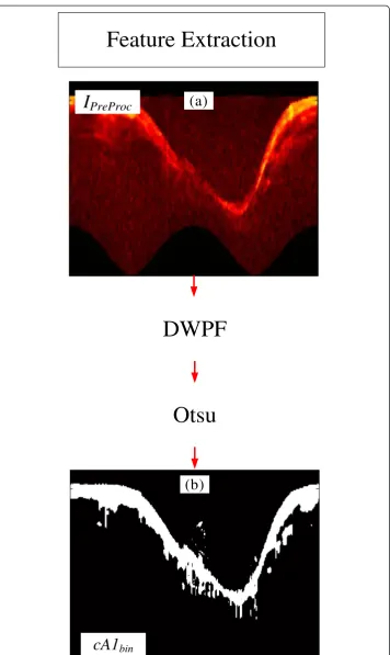
The Feature Extraction uses operations to identify and to distinguish the desired information; hence, increasing discrimination and improving classification [42,45,46]. Following what was successfully applied in [32], a combination of two widely used operations, Discrete Wavelet Packet Frame (DWPF) [42,47] and Otsu threshold [48], were adopted to acquire tissue information (Figure 3).
The Discrete Wavelet Packet Frame (DWPF) is well known and has been established as a very important tool to distinguish the desired information from others, hence increasing the separability between them [4,32,42,47,49,50]. Therefore, one level of decomposition using Daubechies 1 (dB1) was carried out [32,49,50], and the IPreProc
image (Figure 4a) was decomposed into four coefficients (Figure 4b). The wavelet and decomposition coefficient were selected, based on the high correlation with the tissue information. As can be seen in Figure 4c, the Coefficient of Approximation 1, cA1,is the one that best extracted and separate tissue information (Figure 4c, between yellow to red color) from the rest of the image. Once we have the tissue information, the lumen region is directly recognized (Figure 4c). Therefore, cA1was chosen to be the tissue information supplier, hence serving as reference for the binary lumen object re-construction. Binary morphological image reconstruction [32,51] is a very useful tool to estimate and polish previous information, thus increasing the method accuracy and robustness. However, a binarization process should be performed beforehand. Due to the variety of resultant IVOCT image features, according to the artery and the patient being imaged, an adaptive threshold selection is required for a good binarization.
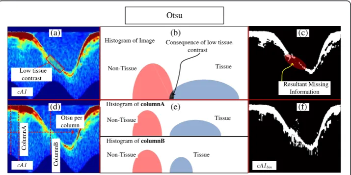
Otsu [48] is a dynamic threshold selection method for dynamic binarization process, in which a histogram is divided into two classes, by seeking for the smallest variance between two clusters, hence providing a good separation for data with bimodal histo-gram. Because the wavelet transformation increases the separability of desired and non-desired information, a highly bimodal histogram is created withcA1, which makes an adequate data to be binarized by Otsu. However, since infrared is distance sensitive, the contrast between tissue and blood may have an angular intensity variation according to the catheter location (Figure 5a, red square). Consequently, data between the two classes may appear in the histogram (Figure 5b), highlighted in black); hence, information may be lost after binarization (Figure 5c, highlighted in red). Nonetheless, the histogram of each column of thecA1usually has two pieces of information (Figure 5d and e), tissue and no-tissue; even when the tissue contrast is low, a bimodal histogram will be obtained (Figure 5e, column b). Therefore, we adopted a local Otsu binarization process, by column; consequently, by performing the mentioned procedure, cA1bin is created,
which corresponds to the binary version of cA1 (Figure 5f ). As a result, the Binary Morphological Reconstruction can be carried out.
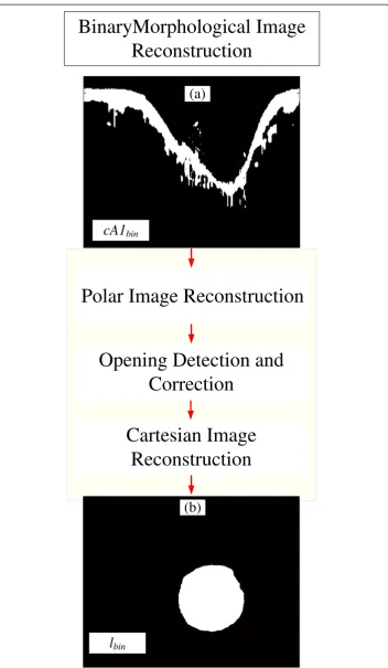
Binary morphological image reconstruction
Binary morphological Image reconstruction is a sequence of combined mathematical
morphology techniques [32,51,52] designed to obtain an accurate binary version of
the desired object. Particularly in this block, we used the previous information,cA1bin
Feature Extraction
(a)
I
PreProc
DWPF
Otsu
cA1
bin(b)
to accomplish this task, the operations for the reconstruction are divided into three
parts, Polar Image Reconstruction, Opening Detection and Correction, and Cartesian
Image Reconstruction (Figure 6). The first, polar image reconstruction, aims to obtain
the complete complementary part of the polar lumen object,lpolar*, (Figure 7). If the
image has branch opening, the opening detection and correction block is performed
to correct it (Figure 8). The final binary lumen object, in the Cartesian domain, is
reconstructed during the Cartesian image reconstruction (Figure 9). Each block is
detailed below:
Polar image reconstruction
Polar Image Reconstruction is a combination of binary morphological procedure applied in the polar domain information,cA1bin, so that it can be refined, and possible missing
(a)
IPreProc cDd1 cA1
cDh1
cDv1
cA1 (b) Lumen Region (c) Tissue Information DWPF
Figure 4Steps of the DWPF stage. (a)Preprocessed Image.(b)DWPF coefficients of 1st decomposition.
(c)Close look of Coefficient of Approximation 1cA1.
(f)
cA1 cA1bin
cA1 (a) (c) (f) Otsu per column Low tissue contrast
Consequence of low tissue contrast Resultant Missing Information (b) (e) ColumnA ColumnB
Histogram ofcolumnA
Histogram ofcolumnB
Histogram of Image
Tissue Tissue Non-Tissue Non-Tissue Tissue Non-Tissue Otsu (d)
Figure 5Steps of the Otsu binarization process. (a)Coefficient of Approximation 1cA1with low tissue contrast highlighted.(b)Illustration of the consequent histogram of allcA1, with tissue and non-tissue information mixed, because of local low tissues contrast.(c)Resultant binarycA1using Otsu threshold in all
cA1;highlighted in red is the resultant missing information due to the local low contrast.(d)Coefficient of Approximation 1cA1with the illustration of the binarization by Otsu per column.(e)Illustration of the consequent histogram of columnA and B ofcA1, since each column has tissue and non-tissue information, no matter the intensity, the histogram of each column will be bimodal, and well separated.(f)cA1bin, after
Polar Image Reconstruction
Cartesian Image
Reconstruction
cA1
binl
binBinaryMorphological Image
Reconstruction
(a)
(b)
Opening Detection and
Correction
information estimated (Figure 7). Due to the range of artery and blood features of patients, spurious noises may appear in a variety of sizes and quantity in the lumen region in the cA1bin(Figure 7a). Since they could also be connected to the tissue
in-formation, these noises must be removed. To remove them, we first disconnect them from the main tissue information block by filtering the image with a morphological opening procedure [51,52] resulting in cA1binFiltered (Figure 7b); second, an upward
(a)
cA1bin
(b)
cA1binFiltered
(d)
lpolar*
Polar Image Reconstruction
Noise
cA1binFilled
(c)
seed D
Figure 7Polar image reconstruction. (a)cA1bin, the binary tissue information.(b)cA1binFiltered, thecA1bin
filtered by an opening procedure.(c)cA1binFilled, is thecA1binFiltered, after a filling procedure.(d)lpolarthe
complementary part of the polar lumen object reconstructed.
(a)
(e)
(b) (c) (d)
(f) (g) (h)
IOriginal IPreProc cA1
lpolar* Corrected polar* Opened
polar* Opened)
Opening
Opening Opening Consequence
of opening
h(l
l
polar*Corrected) Correction
Opening Detection and Correction
h(l
Figure 8Opening detection and correction. (a)IOriginal, Example of an Image with branch opening.
(b)IPreProcconsequent preprocessed image with branch opening.(c)ResultantcA1.(d)lpolar*Openedthe polar
lumen object with branch opening.(e)Height of the final polar image represented by signalh(lpolar*Opened),
high derivatives highlighted in yellow, indicates the presence of opening.(f)h(lpolar*Opened)with correction
being performed, values corresponding to the opening are removed for interpolation.(g)h(lpolar*Corrected),
filling procedure [32,51-53], resulting in cA1binFilled (Figure 7c), followed by an area
selection generating the selected(cA1binFilled) is carried out; finally, a last closing
pro-cedure [51,52] is performed, obtaining the complementary polar lumen object, lpolar*
(Figure 7d). The opening and closing procedures uses circular structuring elements, with 3-pixel andDpixels diameters, respectively. The circular elements is to maintain the smooth contour of object, andD = rMaxpixels, is an adaptive diameter whererMax
correspond to the catheter ring maximum radius [32]. This size assures that possible lumen border irregularities will be attenuated without changing original contour or connecting the object to top of the polar image.
Opening detection and correction
Branch openings are shadows in IVOCT images caused by vessel bifurcations during image acquisition (Figure 8a) [32]. Consequently, they are propagated to the preprocessed image and cA1 (Figures 8b, and c). Because the gap does not produce contrast in its columns, a bi-modal histogram is not generated; thus, the columns corresponding to the gap are binarized as level“1”(lpolar*Opened) (Figure 8d). This causes high derivative
at the lumen border shape of thelpolar*Opened(Figure 8d). Therefore, its detection and
correction is carried out as follows. First, a signal representation of the polar image is created h(lpolar*Opened) (Figure 8e). Second, the signal derivative is calculated, and by
finding values higher than a threshold, the opening is detected. Consequently, the correction initiates by removing all the values corresponding to the gap (Figure 8f ), and performing Piecewise cubic Hermite interpolation (Figure 8g). Finally, the corrected polar image (lpolar*Corrected) (Figure 8h) is then reconstructed using the
interpolated signal. The beginning and end of the gap are identified as the first and last derivative absolute values, respectively higher than the threshold, which is defined as5 standard deviationof all derivative signals.
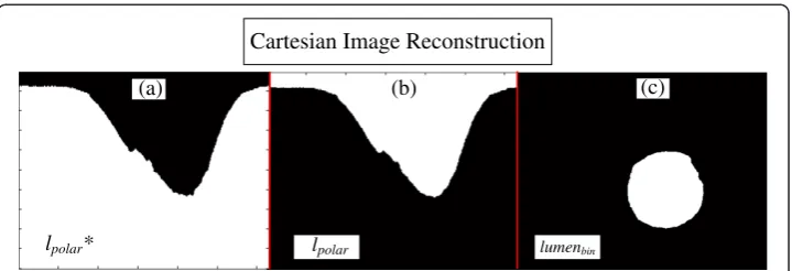
Cartesian image reconstruction
The Cartesian image reconstruction combines an image domain transformation with one last morphological operation, for object polishing. Therefore,lpolar*(Figure 9a) is obtained,
no matter if it went through the opening correction. First the logic negation of lpolar* is
carried out; hence, obtaining the lumen object in the polar domain, Ipolar (Figure 9b).
(a)
lpolar*
(b)
lpolar
(c)
lumenbin
Cartesian Image Reconstruction
Figure 9Cartesian image reconstruction. (a)lpolar* the complementary part of the polar lumen object
reconstructed.(b)lpolar, the polar lumen object reconstructed.(c)lumenbin, final binary lumen object
Finally, the lumen reconstruction, lumenbin(Figure 9c), is concluded by transforming to
the Cartesian domain, ICartesian followed by one last opening operation [51,52], with a
circular structuring element with adaptive diameterRmin pixels (Scirc(Rmin)), whereRmin
is the minimum radius between the center and border of the lumen. This last opening is because possible irregularities in the polar domain will be carried to Cartesian. Using a circular element, these remaining irregularities are removed, and a smooth contour of the object is obtained. Finally, the segmentation is concluded by extracting and placing contour oflumenbinon the Original image [52] (Figure 10).
Results and discussion
The proposed approach was evaluated by segmenting and computing the parameters of accuracy in 290 IVOCT challenges images, which experts established gold standards for the lumen. The database was composed of images with different vessel size and features, such as irregularities and eccentricity of lumen due to thrombus; plaques; branches; se-veral tissue contrasts, and stent implanted 30 and 180 days before acquisition (Figure 10). The image segmentation was performed in a Desktop computer with an Intel Core 2 Duo 2.53 GHz, 4 GB of RAM, Windows Vista 32 bits and MATLAB (2009a) without code optimization. The average time of the lumen segmentation, using the software and computer described above, was (5.9 ± 3)s; apart of being faster than manual seg-mentation, which is above one minute per image, it is more practical and much less exhaustive, since hundreds of images are provided. Code optimization or the use of other computer language, such as C++ or Java certainly may improve even more the processing time.
Assessment of accuracy
The accuracy was obtained by computing from the 290 images the average and standard deviation of the following parameters: True Positive Area Fraction (TP), the False Positive Area Fraction (FP), the False Negative Area Fraction (FN), as well as the Maximum False Positive Deviation (MaxFP), the Maximum False Negative Deviation (MaxFN). Figure 10
shows a sample of the segmented images and their accuracy. The good accuracy can be verified in Table 1, in which theTPyielded more than 99% of agreement, andFPslightly higher than 3%; the method precision and robustness can be seen by the small standard deviation of the indexes a lower than 3% (Table 1), and the smallMaxFP, andMaxFN, with
average smaller than 0.1mmin both indexes, for an image size of 6mm× 6mm.
Segmentation
(a) (b) (c)
(d) (e) (e)
(i) (j) (l)
(m) (n) (o)
(f) (g) (h)
values close to 96%, and 98%, were obtained respectively (Table 1). In [2], their lumen segmentation approach presented an OR near 94%. In the paper presented by [3], an appreciable value of OD close to 97% was obtained. In the semi-automatic method presented in [25] led to results close to 96% and 98% of ORandOD,respectively. As a result, our outcome accuracy rendered efficacy as high as results from mentioned works [2,3,25]. The proposed method has the advantage of being completely auto-matic and also composed by operations known to be simpler and lighter, in which the use of heavy computational tasks, related to energy minimization procedures, were prevented.
The Fourier-Domain OCT technology (FD-OCT) has rapidly increasing its use among cardiologists, and it is currently considered a better choice for IVOCT images. However, since time-domain OCT technology (TD-OCT) is the only available solution in many locations, it is still a useful tool, fulfilling most of the requests of clinics and hospitals, such as follow-up in stent neointimal re-stenosis [18]; hence, it may not be completely replaced very soon. Therefore, tools and methods dedicated to automate TD-OCT image applications are still useful. During the development of the proposed method, the TD-OCT was the only available choice, kindly supported by our collabor-ator (InCor). Using images from others sources, additional ethics protocols and new collaboration policies should have been established. Due to that, the current method-ology was fully created based on TD-OCT technmethod-ology and its image features.
Indeed, because different IVOCT technologies, for instance the TD-OCT and FD-OCT, provide a different image texture, the Feature Extraction and Morphological Operations blocks of this methodology would have to be modified so as to work in both technologies. However it is not in the scope of this work. Therefore, efforts will be made to access FD-OCT technology by additional collaborators and partners; conse-quently, this method will be adapted to work in both technologies. Beyond that, futures works will investigate techniques to create an alternative stent segmentation method; hence, permitting a 2D neo-intima re-stenosis quantification. Additionally, solutions to overcome the challenges of an accurate artery 3D reconstruction will be pursued; hence, providing complete volumetric artery information, speeding up investigation and bring more details to follow in-stent neointimal re-stenosis.
Conclusions
The importance of IVUS and IVOCT segmentation, to directly or indirectly contribute to numerous investigations, is a topic of great concern in many research groups [2-4,27-32,38]. The mentioned papers have provided a variety of interesting methods and good results. Nonetheless, a method that gathers the best of different features such
Table 1 Assessment of accuracy [15]
Parameters
T P F P F N MaxFP MaxF N OR OD
(%) (%) (%) (mm) (mm) (%) (%)
99.29 3.69 0.71 0.1 0.06 95.4 97.8
±2.96 ±2.88 ±2.96 ±0.07 ±0.1 ±4.8 ±2.16
as accuracy, practicability, and good computational demand is still on track. Conse-quently, new and alternative approaches which could improve one or some of the fea-tures are very welcome.
We presented an alternative methodology, combining wavelet and mathematical morphology. This methodology was successfully employed in previous studies [32,38], and was now adapted and applied for the lumen segmentation in IVOCT (TD - OCT) images. The methodology was based on four stages. The first, Preprocessing block, the image is prepared, and normalization and filtering are carried out. The second, Feature Extraction, tissue information is obtained by Wavelet transform and Otsu [48]. Next, Binary Morphological Image Reconstruction is performed. Finally, the segmentation is concluded via Contour Extraction.
Good efficiency, accuracy, computational cost and practicability have motivated the development of the proposed method for IVOCT images. The major specific contribu-tions are: (a) A wavelet associated with an alternative version of Otsu for tissue infor-mation extraction, and; (b) a new sequence of morphological operations, designed to reconstruct lumen object, resulting in an accurate segmentation, even in the presence of bifurcation structures.
Abbreviations
IVOCT:Intravascular optical coherence tomography; IVUS: Intravascular ultrasound; CVD: Cardiovascular disease; InCor: Heart institute of the University of São Paulo Clinic Hospital; TP: True positive; FP: False positive; FN: False negative; MaxFP: Max false positive distance; MaxFN: Max false negative distance; OR: Overlap ratio; OD: Overlap dice; DWPF: Discrete wavelet packet frame.
Competing interests
Other than the grants listed in the acknowledgement section, the authors declare that they have no other competing interests.
Authors’contributions
All the authors contributed to the manuscript creation. MCM designed the investigation, created the methodology and carried out the evaluation, data analysis and the manuscript. DACC contributed to the design of the investigation, methodology, literature revision, data analysis and result interpretation. SSF coordinated the entire work, designed the study and evaluation, managed the interaction with medical doctors, supervised and critically revised the manuscript creation, giving substantial suggestions. All authors read and approved the final manuscript.
Acknowledgements
São Paulo Research Foundation–Brazil ( FAPESP–Process Number: 2012/15721-2), National Council of Scientific and Technological Development, Brazil (CNPq), Heart Institute of São Paulo, Brazil (InCor), Biomedical Engineering Laboratory of the University of São Paulo, Brazil (LEB-USP). The unknown reviewers, who have made important contributions to this work.
Received: 9 April 2013 Accepted: 8 August 2013 Published: 9 August 2013
References
1. Rosamond W, Flegal K, Friday G, Furie K, Go A, Greenlund K, Haase N, Ho M, Howard V, Kissela B, Kittner S, Lloyd-Jones D, McDer-mott M, Meigs J, Moy C, Nichol G, O’Donnell CJ, Roger V, Rumsfeld J, Sorlie P, Steinberger J, Thom T, Wasserthiel-Smoller S, Hong Y:Heart disease and stroke statistics−2007 update: a report from the American heart association statistics committee and stroke statistics subcommittee.Circulation2007,
115(5):e69–e171.
2. Tsantis S, Kagadis G, Katsanos K, Karnabatidis D, Bourantas G, Nikiforidis G:Automatic vessel lumen segmentation and stent strut detection in intravascular optical coherence tomography.Medical Physics2012,39:503–513. 3. Tung KP, Shi W, De Silva R, Edwards E, Rueckert D:Automatical vessel wall detection in intravascular coronary OCT.
Chicago, united States: Proceedings of the IEEE International Symposium on Biomedical Imaging 30 March–02 April 2011; 2011:610–613.
4. Papadogiorgaki M, Mezaris V, Chatzizisis YS, Giannoglou GD, Kompatsiaris I:Image analysis techniques for automated ivus contour detection.Ultrasound Med Biol2008,34(9):1482–1498.
5. Rogowska J, Brezinski ME:Evaluation of the adaptive speckle suppression filter for coronary optical coherence tomography imaging.IEEE Trans Med Imaging2000,19(12):1261–1266.
7. Gil D, Hernandez A, Rodriguez O, Mauri J, Radeva P:Statistical strategy for anisotropic adventitia modelling in ivus.IEEE Trans Med Imaging 20062006,25(6):768–778.
8. Hernandez-Sabate A, Gil D, Fernandez-Nofrerias E, Radeva P, Marti E:Approaching artery rigid dynamics in IVUS. IEEE Trans Med Imaging2009,28(11):1670–1680.
9. Liang Y, Zhu H, Friedman MH:Estimation of the transverse strain tensor in the arterial wall using ivus image registration.Ultrasound Med Biol2008,34(11):1832–1845.
10. Maurice RL, Cloutier G, Ohayon J, Finet G, Cloutier G:Adapting the lagrangian speckle model estimator for endovascular elastography: theory and validation with simulated radio-frequency data.J Acoust Soc Am2004,
116(2):1276–1286.
11. Nyúl LG, Falcão AX, Udupa JK:Fuzzy-connected 3d image segmentation at interactive speeds.Graphical Models
2003,64(5):259–281.
12. Xu C, Pham DL, Prince JL:Image segmentation using deformable models.InHandbook of Medical Imaging: Volume 2. Medical Image Processing and Analysis.Edited by Sonka M, Fitzpatrick JM. Bellingham, WA: SPIE Press; 2000:29–174. 13. Zhang Q, Wang Y, Wang W, Ma J, Qian J, Ge J:Automatic segmentation of calcifications in intravascular
ultrasound images using snakes and the contourlet transform.Ultrasound Med Biol2010,36(1):111–129. 14. Dawant BM, Zijdenbos AP:Image segmentation.InHandbook of medical imaging: medical image processing and
analysis. Volume 2.Edited by Fitzpatrick JM, Sonka M. Bellingham, WA: SPIE Press; 2000:71–128.
15. Udupa JK, LeBlanc VR, Zhuge Y, Imielinska C, Schmidt H, Currie LM, Hirsch BE, Woodburn J:A framework for evaluating image segmentation algorithms.Comput Med Imaging Graph2006,30(2):75–87.
16. Udupa JK, Samarasekera S:Fuzzy connectedness and object definition: theory, algorithms, and applications in image segmentation.Graphical Models and Image Processing1996,58(3):246–261.
17. Lobregt S, Viergever MA:A discrete dynamic contour model.IEEE Trans Med Imaging1995,14(1):12–24. 18. Unal G, Gurmeric S, Carlier SG:Stent implant follow-up in intravascular optical coherence tomography images.
Int J Cardiovasc Imaging2010,26:809–816.
19. Yabushita H, Bouma BE, Houser SL, Aretz HT, Jang IK, Schlendorf KH, Kauffman CR, Shishkov M, Kang DH, Halpern EF, Tearney GJ:Characterization of human atherosclerosis by optical coherence tomography.Circulation2002,
106(13):1640–1645.
20. Bonnema GT, Cardinal KO, Williams SK, Barton JK:An automatic algorithm for detecting stent endothelialization from volumetric optical coherence tomography datasets.Phys Med Biol2008,53:3083–3098.
21. Sawada T, Shite J, Shinke T, Watanabe S, Otake H, Matsumoto D, Imuro Y, Ogasawara D, Paredes OL, Yokoyama M:
Persistent malapposition after implantation of sirolimus-eluting stent into intramural coronary hematoma: Optical coherence tomography observations.Circulation2006,70:1515–1519.
22. Unal G, Bucher S, Carlier S, Slabaugh G, Fang T, Tanaka K:Shape-driven segmentation of the arterial wall in intravascular ultrasound images.IEEE Trans Inf Technol Biomed2008,12(3):335–347.
23. Xu C, Prince J:Snakes, shapes, and gradient vector flow.IEEE Trans Image Process1998,7(3):359–369. 24. Pednekar AS, Kakadiaris IA:Image segmentation based on fuzzy connectedness using dynamic weights.
IEEE Transactions on Image Processing2006,15(6):1555–1562.
25. Cardenas DAC, Moraes MC, Furuie SS:Segmentação do lúmen em imagens de IOCT usando fuzzy connectedness e Reconstrução Binária Morfológica.Rev Bras Eng Biom2013,29(1):1–13.
26. Chan F, Vese LA:Active contours without edges.IEEE Transactions on Image Processing2001,10(2):266–277. 27. Brusseau E, de Korte CL, Mastik F, Schaar J, van der Steen AFW:Fully automatic luminal contour segmentation
in intracoronary ultrasound imaging-a statistical approach.IEEE Trans Med Imaging2004,23(5):554–566. 28. Gurmeric S, Isguder GG, Carlier S, Unal G:A new 3-d automated computational method to evaluate
in-stent neointimal hyperplasia in in-vivo intravascular optical coherence tomography pullbacks. Medical Image Computing and Computer-Assisted Intervention2009,12(2):776–785.
29. Dubuisson F, Kauffmann C, Motreff P, Sarry L:In vivo oct coronary imaging augmented with stent reendothelialization score.Medical Image Computing and Computer-Assisted Intervention2009,12(1):475–482. 30. Kauffmann C, Motreff P, Sarry L:In vivo supervised analysis of stent reendothelialization from optical
coherence tomography.IEEE Trans Med Imaging2010,29(3):807–818.
31. Wang Z, Chamie Z, Bezerra HG, Yamamoto H, Kanovsky J, Wilson DL, Costa MA, Rollins AM:Volumetric quantification of fibrous caps using intravascular optical coherence tomography.Biomedical Optics Express
2012,3(6):1413–1426.
32. Moraes MC, Furuie SS:Automatic coronary wall segmentation in intravascularultrasound images using binary morphological reconstruction.Ultrasound Med Biol2011,37:1486–1499.
33. Bovenkamp EGP, Dijkstra J, Bosch JG, Reiber JHC:User-agent cooperation in multiagent IVUS image segmentation.IEEE Trans Med Imaging2009,28(1):94–105.
34. Sonka M, Zhang X, Siebes M, Bissing MS, Dejong SC, Collins SM, McKay CR:Segmentation of intravascular ultrasound images: a knowledge-based approach.IEEE Trans Med Imaging1995,14(4):719–732.
35. Bourezak R, Lamouche G, Cheriet F:Automatic lumen segmentation from intravascular OCT images.InSPIE 7624, Medical Imaging 2010: Computer-Aided Diagnosis March 2010.Edited by Karssemeijer N, Summers RM A. San Diego, California, USA: SPIE 7624; 2010:R-1–R5.
36. Lu H, Gargesha M, Wang Z, Chamie D, Attizzani GF, Kanaya T, Ray S, Costa MA, Rollins AM, Bezerra HG, Wilson DL:
Automatic stent detection in intravascular OCT images using bagged decision trees.Biomedical Optics Express
2012,3(11):2809–2824.
37. Ughi GJ, Adriaenssens T, Onsea K, Kayaert P, Dubois C, Sinnaeve P, Coosemans M, Desmet W, D’hooge J:
Automatic segmentation of in-vivo intra-coronary optical coherence tomography images to assess stent strut apposition and coverage.Int J Cardiovascular Imag2012,28:229–241.
38. Moraes MC, Furuie SS:An automatic media-adventitia border segmentation approach for IVUS images. Computing in Cardiology2010,37:389–392.
40. Sihan K, Botka C, Post F, de Winter S, Regar E, Hamers R, Bruining N:A novel approach to quantitative analysis of intravascular optical coherence tomography imaging.InProceedings of the Computing in Cardiology 14–17 September 2008.Edited by Murray A. Bologna, Italy: Computing in Cardiology; 2008:1089–1092.
41. Koning G, Dijkstra J, von Birgelen C, Tuinenburg J, Brunette J, Tardif JC, Oemrawsingh P, Sieling C, Melsa S:
Advanced contour detection for three-dimensional intracoronary ultrasound: validation—in vitro and in vivo.Int J Cardiovascular Imag2002,18:235–248.
42. Rangayyan RM:Enhancement.InHandbook of Medical Imaging: Processing and Analysis.Edited by Bankman IN. New York: Academic Press; 2000:3–55.
43. Perona P, Malik J:Scale-space and edge detection using anisotropic diffusion.IEEE Trans Pattern Anal Mach Intell1990,12(7):629–639.
44. Yu Y, Acton S:Speckle reducing anisotropic diffusion.IEEE Trans Image Process2002,11(11):1260–1270. 45. Loew MH:Feature extraction.InHandbook of Medical Imaging: Volume 2. Medical Image Processing and Analysis.
Edited by Sonka M, Fitzpatrick JM. Bellingham, WA: SPIE Press; 2000:273–342.
46. Dougherty G:Digital Image Processing for Medical Applications.3rd edition. New York: Cambridge University Press; 2009.
47. Coifman R, Wickerhauser M:Entropy-based algorithms for best basis selection.IEEE Trans Inf Theory1992,
38(2):713–718.
48. Otsu N:A threshold selection method from gray−level histograms.IEEE Trans Syst Man Cybern C Appl Rev1979,
9(1):62–66.
49. Mallat S:A Wavelet Tour of Signal Processing: The Sparse Way, 3rdEdition.New York: Academic Press; 2009. 50. Misiti M, Misiti Y, Oppenheim G, Poggi JM:Wavelet Toolbox User’s Guide.2nd edition. Natick, MA: The Math Work
Inc; 2000.
51. Goutsias J, Batman S:Morphological methods for biomedical image analysis.InHandbook of Medical Imaging: Volume 2. Medical Image Processing and Analysis.Edited by Sonka M, Fitzpatrick JM. Bellingham, WA: SPIE Press; 2000:175–274.
52. Gonzalez RC, Woods RE:Digital Image Processing.3rd edition. New York: Addison-Wesley; 2008. 53. Soille P:Morphological.Principles and Applications, Springer-Verlag: Image Analysis; 1999.
doi:10.1186/1475-925X-12-78
Cite this article as:Moraeset al.:Automatic lumen segmentation in IVOCT images using binary morphological reconstruction.BioMedical Engineering OnLine201312:78.
Submit your next manuscript to BioMed Central and take full advantage of:
• Convenient online submission
• Thorough peer review
• No space constraints or color figure charges
• Immediate publication on acceptance
• Inclusion in PubMed, CAS, Scopus and Google Scholar
• Research which is freely available for redistribution


![Table 1 Assessment of accuracy [15]](https://thumb-us.123doks.com/thumbv2/123dok_us/9148959.1909274/14.595.117.481.104.169/table-assessment-of-accuracy.webp)
