374
Copyright © 2011-15. Vandana Publications. All Rights Reserved.
Volume-5, Issue-3, June-2015
International Journal of Engineering and Management Research
Page Number: 374-378
Novel Approach To Track Orientation Using Quaternions
Pranao Walekar1, Vipul Pagrut2
1,2
Electrical Engineering, Veermata Jijabai Technological Institute, Matunga, Mumbai, Maharashtra, INDIA
ABSTRACT
A novel way of using quaternions for the orientation of devices tracking system. This approach is a departure from the usual approach of representing rotation in terms of Azimuth and Elevation. The quaternion approach might seem complicated and extensive for a simple task for ground rotation, but it turns out to be an indispensable tool in full 3D spatial rotation in space. An example application of applying quaternion control to a spatial rotating body is also discussed in the document.
Keywords---- solar tracking, quaternions, quaternion control
I. INTRODUCTION
An Orientation tracker is device which orients itself towards a particular point or in reference to that point like the sun. Tracker device is usually a photovoltaic cell array, reflectors, lenses or other optical devices.
In applications such as photovoltaic (PV), trackers are used to minimize the angle of incidence between the incoming sunlight and a photovoltaic panel. This increases the amount of energy produced from a fixed amount of installed power generating capacity. In concentrated photovoltaic (CPV) and concentrated solar thermal (CSP) [5] applications, trackers are used to enable the optical components in the CPV and CSP systems. The optics in concentrated solar applications accepts the direct component of sunlight light and therefore must be oriented appropriately to collect energy. Tracking systems are found in all concentrator applications because such systems do not produce energy unless pointed at the sun. Main focus of this document is on these reflective tracking systems, exploring strategies to direct the sunlight to a desired point.
Future applications of this type of tracking include orientation of devices like solar reflectors in space wherein large banks of reflectors are oriented such that the power of the sun is directed towards earth or to some desired point.
Orientation trackers have also found their way into applications like First-Person-View cameras (FPV). In these devices, an Inertial Measurement Unit (IMU) detects the orientation of the head of the person viewing. These
orientation data is translated to a camera with pan and tilt mechanism. Though these systems do not have reflectors, the concept of quaternions can be applied to them for accurate orientation.
II.
BASIC PROBLEM FORMULATION
The main focus of Quaternion based orientation tracking is in problems concerning orientation of reflectors where there is an emitter and receiver not directly focused on each other. The reflector is used mainly for the purpose of routing rays from the emitter to the receiver. The problem is illustrated figure 1.
Newton-Euler equations are mainly used to model translational and rotational dynamics of rigid body. These are mainly used for controllers and estimators. Although this modeling approach is considered a fundamental one, still it has three drawbacks. Newton-Euler equations inherently suffer from a concept called the “gimbal lock”[4]. This means that a more than one degree of freedom is lost and poses a problem of singularity in calculations. Euler Angle are computationally very expensive. Lock occurs when in 3-D space two axis align losing one degree of freedom.
375
Copyright © 2011-15. Vandana Publications. All Rights Reserved.
DCM has the constraint that each axis should be of unitlength and they should be orthogonal to each other. A DCM can only be multiplied with another DCM for rotation giving a 3x3
results. This creates a system of 9 differential equations to solve. Also the derivative of DCM is also a 3x3 matrix.
Finally in the quaternion way of implementation, all the mentioned problems vanish. A quaternion can be easily be converted to DCM or Euler angles and vice versa. A quaternion and the derivative obtained from it has only four values. There is only one constraint the quaternion should be of unit length. As a result the system has only 4 coupled equations. This greatly reduces the computational effort also reducing the complexity[6]. The only downside is that the quaternions are a complex number and get an intuitive understanding is hard. But converting those to DCM or Euler Angles will make it easy to understand.
The specialty of this paper comes from proposing a quaternion based orientation of these tracking devices. Traditionally in, solar tracking devices azimuth-elevation strategies are used for orientation. These work great or ground but are potentially not suitable for full 3D orientation. The proposed strategy is a generalized one and can be applied to devices on ground as well as those orbiting in space. In scientific literature, relatively few references are available which apply quaternions to tracking systems. When system rotations are described in quaternions, suitable quaternion based control systems can also be developed which require less computational power to derive the control law.
The rest of the article is structured as follows. In Section III the fundamental properties and the corresponding algebra of the quaternion mathematics are being presented, while in Section IV application of quaternion to rotations is explained and strategies for quaternion based tracking are explored. Section V shows the simulation results and finally in Section VI conclusions are drawn.
III.
QUATERNION MATH
This section is going to present the basic idea behind the quaternions and its associated concepts. This will give the reader some consistency and will help build mathematical background for the concept. The reader can refer the following publications [1][2] for in depth understanding and analysis of this novel mathematical concept.
A quaternion can be represented in many ways. Representations shown in (1) and (2) are two of them. The quaternions contain real and imaginary part. 𝑞𝑞0 forms the real part while the 𝑞𝑞1𝑡𝑡𝑡𝑡𝑞𝑞3 form the imaginary or vector part.
𝑞𝑞= 𝑞𝑞0+ 𝑞𝑞1𝑖𝑖+ 𝑞𝑞2𝑗𝑗+ 𝑞𝑞3𝑘𝑘 (1)
𝑞𝑞= [𝑞𝑞0𝑞𝑞1𝑞𝑞2𝑞𝑞3]T (2)
Multiplication of two quaternions p, q is performed by a operation called Hamilton product, denoted as ⊗. The operation is shown in the following equations. Rotational Quaternions can be multiplied. Multiplication of 2 quaternions p and q is given below. Quaternion multiplication is non-commutative.
𝑝𝑝 ⊗q = �
𝑝𝑝0𝑞𝑞0− 𝑝𝑝1𝑞𝑞1− 𝑝𝑝2𝑞𝑞2− 𝑝𝑝3𝑞𝑞3 𝑝𝑝0𝑞𝑞1+ 𝑝𝑝1𝑞𝑞0+ 𝑝𝑝2𝑞𝑞3− 𝑝𝑝3𝑞𝑞2 𝑝𝑝0𝑞𝑞2− 𝑝𝑝1𝑞𝑞3+ 𝑝𝑝2𝑞𝑞0+ 𝑝𝑝3𝑞𝑞1 𝑝𝑝0𝑞𝑞3+ 𝑝𝑝1𝑞𝑞2− 𝑝𝑝2𝑞𝑞1+ 𝑝𝑝3𝑞𝑞0 �
𝑝𝑝 ⊗q = Q(p)q = �
𝑝𝑝0 −𝑝𝑝1 −𝑝𝑝2 −𝑝𝑝3 𝑝𝑝1 𝑝𝑝0 −𝑝𝑝3 𝑝𝑝2 𝑝𝑝2
𝑝𝑝3 −𝑝𝑝2𝑝𝑝3 𝑝𝑝𝑝𝑝10 −𝑝𝑝𝑝𝑝01 � �
𝑞𝑞0 𝑞𝑞1 𝑞𝑞2 𝑞𝑞3 �
Quaternion used for rotations are of unit length. Norm or the length of a quaternion is like a complex number and is shown in (3).
𝑁𝑁𝑡𝑡𝑁𝑁𝑁𝑁(𝑞𝑞) = ‖𝑞𝑞‖= �𝑞𝑞02+ 𝑞𝑞12+ 𝑞𝑞22+ 𝑞𝑞32 (3)
Complex of a quaternion is similar to normal complex numbers. In conjugation operation, the sign of the complex parts is inverted as shown in equation(4).
Conj(q) = 𝑞𝑞∗= [𝑞𝑞
0 −𝑞𝑞1 −𝑞𝑞2 −𝑞𝑞3]𝑇𝑇
(4) Also the inverse of a quaternion is similar to the normal complex numbers. This is shown in equation (5). When the length of a quaternion is unity, the inverse is equivalent to the conjugate of the same quaternion.
Inv(q) = 𝑞𝑞−1= 𝑞𝑞∗
‖𝑞𝑞‖2 (5)
After some manipulation the derivative of a quaternion can be obtained. They can be represented in two ways: a) as shown in equation (6) when the angular velocity is in reference frame that is fixed, (b) as shown in equation (7) if angular velocity is in body frame of reference. It is important to note that equations represented are derived using left hand notation. To get results in right hand notation conjugate of derivative quaternion must be used.
𝑞𝑞̇𝜔𝜔(𝑞𝑞,𝜔𝜔) = 12 𝑞𝑞 ⊗ �𝜔𝜔�0 = 12 𝑄𝑄(𝑞𝑞)�𝜔𝜔�0 (6) 𝑞𝑞̇𝜔𝜔(𝑞𝑞,𝜔𝜔′) = 12�𝜔𝜔′� ⊗ 𝑞𝑞0 = 12𝑄𝑄�(𝑞𝑞)�𝜔𝜔′�0 (7)
where 𝜔𝜔= [𝜔𝜔𝑥𝑥,𝜔𝜔𝑦𝑦,𝜔𝜔𝑧𝑧]𝑇𝑇. A unit quaternion can be used in rotational operations. For operation of rotation, both the quaternion and its conjugated is needed for the operation as shown in equation(8). This rotates the vector v from the fixed frame to the body frame represented by q.
376
Copyright © 2011-15. Vandana Publications. All Rights Reserved.
This rotation in equation (8) can be rewritten by replacing vwith the x, y and z axis, as it is being displayed in the following equations (9-10) and (11).
𝑅𝑅𝑥𝑥(𝑞𝑞) =𝑞𝑞 ⊗ �
0 1 0 0
� ⊗ 𝑞𝑞∗= �𝑞𝑞0
2+ 𝑞𝑞12− 𝑞𝑞22− 𝑞𝑞32
2(𝑞𝑞1𝑞𝑞2+ 𝑞𝑞0𝑞𝑞3)
2(𝑞𝑞1𝑞𝑞3− 𝑞𝑞0𝑞𝑞2) � (9)
𝑅𝑅𝑦𝑦(𝑞𝑞) =𝑞𝑞 ⊗ �
0 0 1 0
� ⊗ 𝑞𝑞∗= �𝑞𝑞2(𝑞𝑞1𝑞𝑞2− 𝑞𝑞0𝑞𝑞3) 02− 𝑞𝑞12+ 𝑞𝑞22− 𝑞𝑞32
2(𝑞𝑞2𝑞𝑞3+ 𝑞𝑞0𝑞𝑞1) � (10)
𝑅𝑅𝑧𝑧(𝑞𝑞) =𝑞𝑞 ⊗ �
0 0 0 1
� ⊗ 𝑞𝑞∗= � 2(2(𝑞𝑞1𝑞𝑞2𝑞𝑞2𝑞𝑞3+ − 𝑞𝑞0𝑞𝑞3𝑞𝑞0𝑞𝑞1))
𝑞𝑞02− 𝑞𝑞12− 𝑞𝑞22+ 𝑞𝑞32� (11)
If only the vector part of the quaternion is taken into account, the result is a rotation matrix. This matrix rotates a point in the fixed frame of reference as shown in equation (12). On the other hand if the coordinate system is rotated, there is a change in the angle sign as shown in equation (13). Same result arises when the quaternion in the equation (8) is conjugated
𝑅𝑅(𝑞𝑞) = [𝑅𝑅𝑥𝑥(𝑞𝑞)𝑅𝑅𝑦𝑦(𝑞𝑞)𝑅𝑅𝑧𝑧(𝑞𝑞)] (12)
𝑅𝑅(𝑞𝑞) = �𝑅𝑅𝑥𝑥(𝑞𝑞) 𝑇𝑇 𝑅𝑅𝑦𝑦(𝑞𝑞)𝑇𝑇 𝑅𝑅𝑧𝑧(𝑞𝑞)𝑇𝑇
� (13)
The rotation can also be represented using a rotation vector as denoted in equation (14), where u is the rotation
axis (unit vector) and α is the angle of rotation. Using this
notation can have many benefits when creating an error or specifying a reference as it has a direct physical connection.
𝑞𝑞= cos�𝛼𝛼2�+𝑢𝑢. sin(𝛼𝛼2) (14) Finally, for representing quaternion rotations in a more intuitive manner, the conversion from Euler angles to quaternion and from quaternion to Euler angle can be performed by utilizing the following two equations respectively. This property is very useful in case that the aim is to represent an orientation in angles, while retaining the overall dynamics of the system in a quaternion form.
𝑞𝑞=
⎣ ⎢ ⎢
⎡sin(cos(∅∅/2) cos(/2) cos(𝜃𝜃𝜃𝜃/2) cos(/2) cos(𝜑𝜑𝜑𝜑/2)/2) + sin(−cos(∅∅/2) sin(/2) sin(𝜃𝜃𝜃𝜃/2) sin(/2) sin(𝜑𝜑𝜑𝜑/2)/2)
cos(∅/2) sin(𝜃𝜃/2) cos(𝜑𝜑/2) + sin(∅/2) cos(𝜃𝜃/2) sin(𝜑𝜑/2) cos(∅/2) cos(𝜃𝜃/2) sin(𝜑𝜑/2)−sin(∅/2) cos(𝜃𝜃/2) cos(𝜑𝜑/2)⎦⎥
⎥ ⎤
(15)
�∅𝜃𝜃 𝜑𝜑�=�
𝑎𝑎𝑡𝑡𝑎𝑎𝑎𝑎2(2(𝑞𝑞0𝑞𝑞1− 𝑞𝑞2𝑞𝑞3),𝑞𝑞02− 𝑞𝑞12− 𝑞𝑞22+ 𝑞𝑞32)
asin(2(𝑞𝑞0𝑞𝑞2− 𝑞𝑞1𝑞𝑞3))
𝑎𝑎𝑡𝑡𝑎𝑎𝑎𝑎2(2(𝑞𝑞0𝑞𝑞3+ 𝑞𝑞1𝑞𝑞2),𝑞𝑞02+ 𝑞𝑞12− 𝑞𝑞22− 𝑞𝑞32) �
(16)
IV.
QUATERNIONS IN ORIENTATION
Consider a reference frame. Now also consider a body frame. Let this body frame be at the center of the tacking device. Unit vectors in the direction of the receiver and emitter are calculated with respect to this body frame. The
directional vector for emitter is represented by norm of the vector connecting the center of tracking device to the emitter. Same can be obtained for the receiver. Therefore, two vectors are obtained each for transmitter and receiver. From these two vectors their angle bisector is to be obtained.
Ideally this angle bisector should coincide with the normal
to the surface of the reflecting device. If it does not, then an error quaternion is to be obtained such that when that quaternion rotation is applied to reflector, the normal of the reflector aligns with the angle bisector of the emitter and reflector rays. When this happens, it can be successfully said that the ray from the emitter is directed towards the receiver.
Mathematically the above strategy can be described as in the following. According to the frame of reference of tracker, the direction vector of emitter is obtained. Let the vector be denoted by e.
𝑒𝑒= �𝑒𝑒𝑒𝑒𝑥𝑥𝑦𝑦 𝑒𝑒𝑧𝑧
� (17)
where,
‖𝑒𝑒‖=�𝑒𝑒𝑥𝑥2+ 𝑒𝑒𝑦𝑦2+ 𝑒𝑒𝑧𝑧2= 1 (18)
Also same can be obtained for receiver
𝑁𝑁= �𝑁𝑁𝑁𝑁𝑥𝑥𝑦𝑦 𝑁𝑁𝑧𝑧
� (19)
where,
‖𝑁𝑁‖=�𝑁𝑁𝑥𝑥2+ 𝑁𝑁𝑦𝑦2+ 𝑁𝑁𝑧𝑧2= 1 (20)
Second step is to find the angle bisector for these two vectors. This can be found as:
𝑨𝑨𝒃𝒃 =‖𝒆𝒆‖𝒓𝒓+ ‖𝒓𝒓‖𝒆𝒆 (21)
The magnitude of the angle bisector obtained might not be equal to 1. There to normalize the bisector
𝑎𝑎𝑏𝑏= ‖𝐴𝐴𝐴𝐴𝑏𝑏𝑏𝑏‖ (22)
The direction vector of the normal to the tracker will always be:
𝑎𝑎𝑡𝑡 = �
0 0 1�
(23)
377
Copyright © 2011-15. Vandana Publications. All Rights Reserved.
coincide then, a rotation quaternion is to be found out.When this quaternion is applied to the tracker, it aligns with the angle bisector.
When the reference frame and body frame are aligned, the rotation quaternion is given by
𝑞𝑞0= �
1 0 0 0
� (24)
CALCULATING ERROR QUATERNION
If the normal of tracker, does not align with the angle bisector 𝑎𝑎𝑏𝑏 then error quaternion needs to be calculated. In this approach, rotation quaternion is calculated by obtaining the magnitude of the angle and vector about which the system needs to be rotated. The angle between two vectors is calculated as:
𝑎𝑎𝑏𝑏.𝑎𝑎𝑡𝑡= ‖𝑎𝑎𝑏𝑏‖‖𝑎𝑎𝑡𝑡‖𝑐𝑐𝑡𝑡𝑐𝑐𝜃𝜃 (25)
Since ‖𝑎𝑎𝑏𝑏‖= 1 &‖𝑎𝑎𝑡𝑡‖= 1
𝜃𝜃=𝑐𝑐𝑡𝑡𝑐𝑐−1(𝑎𝑎
𝑏𝑏.𝑎𝑎𝑡𝑡) (26)
To obtain the vector about which the system needs to be rotated, cross product of 𝑎𝑎𝑏𝑏 and 𝑎𝑎𝑡𝑡 needs to be taken.
𝑢𝑢′=𝑎𝑎𝑡𝑡×𝑎𝑎𝑏𝑏 (27)
Again 𝑢𝑢′needs to be normalized
𝑢𝑢= ‖𝑢𝑢′‖𝑢𝑢′
Now combining equations (14), (26) and (27) error quaternion can be obtained.
𝑞𝑞𝑒𝑒𝑁𝑁𝑁𝑁 = cos�𝜃𝜃2�+𝑢𝑢. sin�𝜃𝜃2� (28)
APPLICATION OF ERROR QUATERNION
Let us consider a case of Concentrated Solar Plant (CSP), as shown in figure 3, consisting of a farm of heliostat mirrors and a central tower. All these mirrors need to point the solar rays towards a particular point on the tower.For a particular mirror in the farm the direction of receiver (i.e. a point on the tower) will always be constant. That is the 𝑁𝑁𝑖𝑖 vector for that particular heliostat mirror. The direction of the sun is variable, since sun moves across the sky over the period of a day. The rays for the sun can be considered parallel. Therefore, the direction vector of the sun which in our case is the emitter is equal for all the mirrors.
Using the above presented strategy, error quaternion𝑞𝑞𝑖𝑖 for each mirror can be calculated. In this way, error quaternion for the entire farm can be calculated for each time interval in a day. The generated quaternion can then be directly fed to the respective controllers of heliostat mirrors for orientation or can be converted to angles and then fed to the controllers.
The strategy of converting quaternions to Euler angles is also explained in above sections.
The above figure shows a typical heliostat mirror assembly. The case gets more interesting in application in space. Traditional orientation techniques of azimuth and elevation can be difficult to apply to systems in orbit. In these areas, quaternion techniques can provide an easy way to calculate orientation of various tracking devices.
V.
SIMULATION RESULTS
378
Copyright © 2011-15. Vandana Publications. All Rights Reserved.
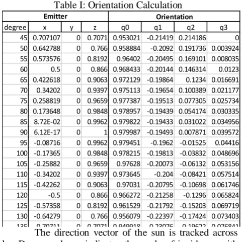
Table I: Orientation CalculationThe direction vector of the sun is tracked across sky. Degree column indicates the angle of incidence with ground. x, y and z component of the emitter vector are derived for each degree of incidence for that particular day. Using the strategy described in the paper, the respective quaternions are calculated. These quaternions can then be fed to the heliostat mirrors and desired orientation can be attained.
VI.
CONCLUSION
In this document, a full quaternion based orientation tracking strategies have been presented. The novelty of this paper is to use quaternions for attitude of
tracking devices to avoid problems of singularities due to gimbal lock. Moreover, the idea has been generalized to apply it on various other system requiring orientation. Future works can include developing control system for tracking devices taking into account system dynamics. The quaternion approach greatly reduces computational costs compared to implementation of Euler angles. Simulation results have been presented showing computations of orientation quaternions.
REFERENCES
[1] J. B. Kuipers, Quaternions and Rotation Sequences, P. U. Press, Ed., 1998.
[2] J. Diebel, “Representing attitude: Euler angles, unit quaternions, and rotation vectors,” 2006.
[3] T. Bresciani, “Modelling, identification and control of a quadrotor helicopter,” Ph.D. dissertation, Lund University, 2008.
[4] J. Harrison, J. Gallagher, and E. Grace, “An algorithm providing allattitude capability for three-gimballed inertial systems,” IEEE Transactions on Aerospace and Electronic Systems, vol. AES-7, no. 3, pp. 532–543, 1971.
[5] Christopher L. Martin; D. Yogi Goswami (2005). Solar energy pocket reference. Earthscan. p. 45. ISBN 978-1-84407-306-1.
[6] J. T. T. H. . T. C. Grant Baldwin, Robert Mahony, “Complementary filter design on the special euclidean group so(3),” IEEE Conference on Decision and Control, vol. 44, 2005.
[7] M. Young, The Technical Writer’s Handbook. Mill Valley, CA: University Science, 1989.
degree x y z q0 q1 q2 q3
45 0.707107 0 0.7071 0.953021 -0.21419 0.214186 0
50 0.642788 0 0.766 0.958884 -0.2092 0.191736 0.003924 55 0.573576 0 0.8192 0.96402 -0.20495 0.169101 0.008035
60 0.5 0 0.866 0.968433 -0.20144 0.146314 0.0123
65 0.422618 0 0.9063 0.972129 -0.19864 0.1234 0.016691 70 0.34202 0 0.9397 0.975113 -0.19654 0.100389 0.021177 75 0.258819 0 0.9659 0.977387 -0.19513 0.077305 0.025734 80 0.173648 0 0.9848 0.978957 -0.19439 0.054174 0.030335 85 8.72E-02 0 0.9962 0.979822 -0.19433 0.031022 0.034956
90 6.12E-17 0 1 0.979987 -0.19493 0.007871 0.039572
95 -0.08716 0 0.9962 0.979451 -0.1962 -0.01525 0.04416 100 -0.17365 0 0.9848 0.978215 -0.19813 -0.03832 0.048696 105 -0.25882 0 0.9659 0.97628 -0.20073 -0.06132 0.053156 110 -0.34202 0 0.9397 0.973645 -0.204 -0.08421 0.057514 115 -0.42262 0 0.9063 0.97031 -0.20795 -0.10698 0.061746
120 -0.5 0 0.866 0.966272 -0.21258 -0.1296 0.065824
125 -0.57358 0 0.8192 0.961529 -0.21792 -0.15203 0.069719 130 -0.64279 0 0.766 0.956079 -0.22397 -0.17424 0.073403 135 -0 70711 0 0 7071 0 949918 -0 23076 -0 19622 0 076841