Simulation of Digital Modulation Techniques
Using MATLAB
1
Neha Sharma, 2Yogendra Yadav
1,2
Assistant Professor, Electronics & Communication Department, Prestige Institute of Engineering and Science, Indore (MP), India
Abstract— In Digital modulation the message signal is in the digital form and the carrier wave is in sinusoidal form. In this technique the Amplitude, Frequency or Phase of carrier varies according to message (Baseband) signal. There are various type of digital modulation technique like Amplitude Shift Keying (ASK), Phase Shift Keying (PSK), Frequency Shift Keying (FSK), Quadature Phase Shift Keying (QPSK), Differential Phase Shift Keying (DPSK) and other digital demodulation technique. Simulation is the imitation of the operation of a real-world process or system over time. The act of simulating something first requires that a model be developed; this model represents the key characteristics or behaviors of the selected physical or abstract system or process. The model represents the system itself, whereas the simulation represents the operation of the system over time. Simulation is used in many contexts, such as simulation of technology for performance optimization, safety engineering, testing, training, education, and video games. So in this paper we will simulate and verify the waveform of modulating wave, carrier wave and modulated wave of Amplitude Shift Keying (ASK), Phase Shift Keying (PSK), Frequency Shift Keying FSK, Quadature Phase Shift keying (QPSK).
Keywords- Digital Modulation, Simulation, Run, ASK, PSK, FSK, QPSK.
I. INTRODUCTION
In digital modulation, an analog carrier signal is modulated by a discrete signal. Digital modulation methods can be considered as digital-to-analog conversion, and the corresponding demodulation or detection as analog-to-digital conversion. The techniques used to modulate digital information so that it can be transmitted via microwave, satellite or down a cable pair is different to that of analogue transmission. The data transmitted via satellite or microwave is transmitted as an analogue signal. The techniques used to transmit analogue signals are used to transmit digital signals. The problem is to convert the digital signals to a form that can be treated as an analogue signal that is then in the appropriate form to either be transmitted down a twisted cable pair or applied to the RF stage where is modulated to a frequency that can be transmitted via microwave or satellite. The equipment that is used to convert digital signals into analogue format is a modem.
II. TYPES OF DIGITAL MODULATION TECHNIQUE There are many different modulation techniques which are used in Modem. List of common digital modulation techniques are:
Amplitude Shift Key Modulation(ASK)
Frequency Shift Key Modulation(FSK)
Binary Phase Shift Key Modulation(BPSK)
Quadrature Phase Shift Key Modulation(QPSK)
Quadrature Amplitude Modulation(QAM)
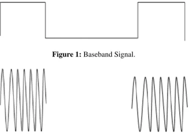
A. Amplitude Shift Keying (ASK):
In Amplitude Shift Keying method the amplitude of carrier switches according to baseband signal. The ASK waveform can be represented as:
Figure 1: Baseband Signal.
Figure 2: ASK Modulated Waveform.
ASK Waveform act as an ON /OFF. Pulse shaping can be employed to remove spectral spreading.
ASK demonstrates poor performance, as it is heavily affected by noise, fading, and interference.
ASK can be used in Low data rate application.
B. Phase Shift Keying (PSK):
Volume 1, Issue 10, December 2012 exactly where the constellation points are positioned, and in
this figure they are shown on the real axis, at 0° and180°. This modulation is the most robust of all the PSKs since it takes the highest level of noise or distortion to make the demodulator incorrect decision. It is, however, only able to modulate at 1bit/symbol (as seen in the figure) and so is unsuitable for high data-rate applications when bandwidth is limited.
Figure 3: Baseband Signal.
\
Figure 4: BPSK Modulated Waveform.
The transmitted BPSK signal is either:
Binary data is often conveyed with the following signals: For binary "0 and for binary "1". The signal space diagram of BSPK is shown in figure 5.
The drawback of BPSK is rapid amplitude change between symbols due to phase discontinuity, which requires infinite bandwidth. Binary Phase Shift Keying (BPSK) demonstrates better performance than ASK and BFSK. BPSK can be expanded to an M-ary scheme, employing multiple phases and amplitudes as different states.
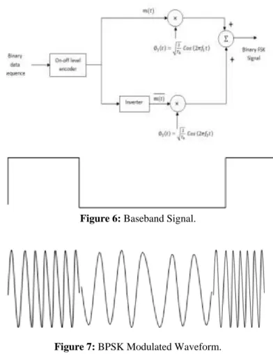
C. Frequency Shift Key Modulation (FSK):
In FSK the frequency of carrier varies according to baseband signal when we transmit 1 then frequency of carrier wave increases and for 0 bit the frequency will be low
Figure 6: Baseband Signal.
Figure 7: BPSK Modulated Waveform.
In ITU-T V.21 modem standard uses FSK
FSK can be expanded to a M-ary scheme, employing multiple frequencies as different states.
D. Quadrature Phase Shift Keying (QPSK):
Quadrature Phase Shift Keying (QPSK) has twice the bandwidth efficiency of BPSK, since 2 bits are transmitted in a single modulation symbol. The phase of the carrier takes on
1 of 4 equally spaced values, such as where each value of phase corresponds to a unique pair of
The implementation of QPSK is more general than that of BPSK and also indicates the implementation of higher-order PSK. Writing the symbols in the constellation diagram in terms of the sine and cosine waves used to transmit them: This yields the four phases π/4, 3π/4, 5π/4 and 7π/4 as needed. This results in a two-dimensional signal space with unit basis functions The first basis function is used as the in-phase component of the signal and the second as the quadrature component of the signal. Hence, the signal constellation consists of the signal-space 4 points The factors of 1/2 indicate that the total power is split equally between the two carriers. Comparing these basis functions with that for BPSK shows clearly how QPSK can be viewed as two independent BPSK signals. Note that the signal-space points for BPSK do not need to split the symbol (bit) energy over the two carriers in the scheme shown in the BPSK constellation diagram. QPSK systems can be implemented in a number of ways. An illustration of the major components of the transmitter and receiver structure is shown below.
Conceptual transmitter structure for QPSK. The binary data stream is split into the in- phase and quadrature-phase components. These are then separately modulated onto two orthogonal basis functions. In this implementation, two sinusoids are used. Afterwards
The Signal Constellation diagram of QPSK is shown in below.
Figure 8: Signal constellation diagram for QPSK with gray coding.
III. SIMULATION USING MATLAB
Simulink provides an environment where you model your physical system and controller as a block diagram. In Matlab Binary sequence are generated by PN Sequence generator. This PN sequence works as a modulating signal. Modulated wave are generated by switching device as a multiplier or a
switch. The procedure for developing the different modulation scheme us explained below.
A. Amplitude Shift Keying:
1. Open Simulink library Browser by Click on the Simulink in command window.
2. Click on the file.
3. Click on the Communication Block Set and drag PN Sequence and a sine wave generator block for carrier. 4. Click on the Math Operation and drag Product in the file. 5. Click on the Sink tab and drag out the scope to the file. 6. Now connect PN sequence an a sine wave generator to the
product and a output with scope.
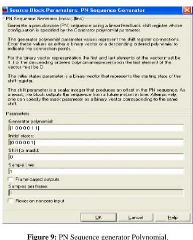
7. Double click on the PN sequence generator then PN sequence generator screen opens as shown below.
Figure 9: PN Sequence generator Polynomial.
Volume 1, Issue 10, December 2012
Figure 11: ASK Using Switch.
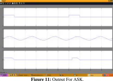
Start Simulation and observe output as shown below:
Figure 11: Output For ASK.
B. Frequency Shift Keying (FSK):
Repeat Procedure 1,2,3,4,5,6,7 only difference is that in place of one sine wave generator two sine wave generator are used.
Figure 12: FSK Using Product.
Figure 13: FSK Using Switch.
Figure 14: Output for FSK.
C. Phase Shift Keying (PSK):
PSK modulated block diagram is shown below figure 15.
Figure 15: Phase Shift Keying.
Figure 16: Output of PSK.
D. Quadrature Phase Shift Keying (QPSK):
It is a digital modulation technique in which two bit is transmitted per symbol. Quadrature Phase Shift Keying Technique is used to reduce transmission bandwidth.
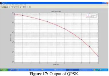
The waveform of QPSK (Bit Error Rate with respect to signal to Noise Ratio) are shown below figure 17.
Figure 17: Output of QPSK.
IV. RESULT & CONCLUSION
Simulation model are interactive method to analysis the concept of communication system. It is interactive because we can change the parameter and immediately verify the result. It can also verify in VHDL and Lab View.
REFERENCES
[1] Advanced Electronic Communications Systems (Fifth Edition); Tomasi, Wayne;Prentice-Hall, Inc.: Upper Saddle River, New Jersey 2001; pp. 47.
[2] W. Dai, Y. Wang, J. Wang, Joint power estimation and modulation classification using second and higher statistics, WCNC 2002 - IEEE Wireless Communications and Networking Conference, No. 1, 2002, pp. 767 – 770. [3] L. Hong, K. C. Ho, Identification of digital Modulation
types using the wavelet transform, MILCOM 1999 - IEEE Military Communications Conference, No. 1, 1999, pp. 427 – 431.
[4] L. Hong, K. C. Ho, BPSK and QPSK modulation Classification with unknown signal levels, MILCOM 2000 - IEEE Military Communications Conference, No. 2, 2000, pp. 976-980.
[5] F. Liedtke, Computer simulation of an automatic Classification procedure for digitally modulated Communication signals with unknown parameters, Signal Processing, 1984, Vol. 6, No. 4, pp. 311–323.
[6] L. Chaari, M. Fourati, N. Masmoudi, L. Kamoun, An Adaptive Coded Modulation with Multi-Levels QoS Analysis in Multimedia Environment, WSEASTransactions on Communications, 2009, Issue 6,Vol. 8.
About Author:-
Ms. Neha Sharma received B.Sc. degree from PMB Gujrati Science College, Indore, Madhya Pradesh, India in 2005 and M.Sc. degree from School of Electronics, DAVV, Indore, Madhya Pradesh, India in 2007. She received M.Tech degree from School of Electronics, DAVV, Indore, Madhya Pradesh, India in 2011. She is now working as Assistant Professor in Department of Electronics and Communication Engineering at Prestige Institute of Engineering & Science, Indore, M.P., India. Her interested field of research is Mobile Communication and Wireless Communication.