229 Volume-4, Issue-1, February-2014,ISSN No.: 2250-0758
International Journal of Engineering and Management Research
Available at:
Page Number: 229-233
Raman Effect for Gain Flatenning in an Optical Communication System
Er. Maninder Kumar Duggal1, Er. Gurpreet Bharti2 1
Student M.Tech (ECE), Yadavindra College of Engineering, Talwandi Saboo Punjabi University, Patiala, Punjab, INDIA 2
Assistant Professor, Department of ECE, Yadavindra College of Engineering, Talwandi Saboo Punjabi University, Patiala, Punjab, INDIA
ABSTRACT
Both attenuation and dispersion contribute to determine a maximum transmission span beyond which the optical signal that is, a suitable coding of an analog waveform or a sequence of digital pulses cannot be detected any longer nor decoded with sufficient precision for long distance transmission of information. The availability of optical amplifiers really represents a key point regarding the attenuation limit of optical networks. Optical amplification allows system designers to increase network performance, and in the meantime lower the number of repeaters and simplify the network. This means lower installation and maintenance costs and higher link reliability. Roughly speaking, it can be said that optical amplification has overcome attenuation limits. This paper presents the use of Raman amplification for gain flattening in an optical communication system.
Keywords: Anti-Stoke, Pumping, Raman Effect,
Scattering, Stoke.
I.
INTRODUCTION
The transmission of near-infrared signals in an optical fiber is affected by two fundamental limitations: attenuation and dispersion. Attenuation is due to the partial transparency of the glass constituting the fiber, and causes a gradual reduction in signal amplitude during propagation. On the other hand, dispersion causes distortion and broadening of time-modulated pulses traveling through the fiber. This second mechanism is due to the fact that signal components at different wavelengths travel at different speeds because of the dispersive nature of glass and because of guided propagation in a spatially finite medium [1]. Both attenuation and dispersion contribute to determine a maximum transmission span beyond which the optical signal that is, a suitable coding of an analog waveform or a sequence of digital pulses cannot be detected any longer nor decoded with sufficient precision for long distance transmission of information.
Transmission of signals in an optical fiber mostly takes place around 1310 nm and 1550 nm. The typical
attenuation of silica fibers is of the order of 0.2 dB/km at 1550 nm and 0.35 dB/km at 1310 nm. It is more difficult to indicate a typical dispersion limit, since this not only depends on the fiber through the dispersion coefficient and the operating wavelength, but is also influenced by the optical source spectral width, bit rate, and transmission format [1]. For these reasons there is a need to install a number of suitably spaced repeaters in order to perform the functions of regenerating, reshaping, and retiming the signal along an optical link. They detect the optical signal arriving from the preceding transmission span, make the necessary corrections at the electronic level, and activate a transmitter diffusing the optical signal on the following transmission length.
230 Figure 1: Schematic Representation of an Optical Amplifer
This excitation brings the active medium in conditions of population inversion, in order to make more probable emission than absorption processes at the signal wavelength. In these conditions part of the pump energy can be transferred to the signal wavelength which is amplified at its expense through stimulated emission processes in the inverted active medium. In practice, it is a matter of finding and fabricating an active medium having characteristics matched with the wavelength of the transmission signal and with the available pump sources.
II.
OPTICAL AMPLIFIERS
Optical amplifiers for telecommunications can be classified into optical fiber amplifiers, (OFAs), semiconductor optical amplifiers, (SOAs), and Raman fiber devices. Most mature components for optical communications are represented by OFAs, and secondarily by SOAs. Active media for OFAs are rare-earth elements which are used as dopants in the glass matrix of an optical fiber. These amplifiers have very attractive features such as the practical absence of nonlinearities, low coupling losses to the transmission line, very low dependence of gain on light polarization, and wide transparency to signal format and bit rate. On the other hand, SOAs are easily integrable with other optical devices and circuits, consume less power, are made by a lower number of components, and thus are more compact and economical. In SOAs the active medium is made up by an alloy of semiconductor elements belonging to the III and V groups like phosphorus, gallium, indium, and arsenic which also has the function of providing electrical conductivity for device pumping. The other main differences between fiber and semiconductor devices are in the pumping system which is optical for OFAs and electrical for SOAs and in the gain dynamic response. The latter quantity is related to the linearity of the amplifier and explains the much stronger impact that OFAs actually have on telecommunications with respect to SOAs. OFAs have very slow gain dynamics, with lifetimes on the order of 10 ms [4]. Conversely, SOAs have much more rapid response, with times ~0.1 ns [5] and even faster than 1 ps, with extremely rapid relaxation processes. This means that OFAs are practically unaffected by signal modulation at frequencies over a few kilohertz, and are then immune from interference phenomena between different optical channels
simultaneously injected in the amplifier, such as saturation-induced crosstalk and intermodulation distortion. On the contrary, SOAs are subject to relevant saturation phenomena even in the presence of a single, strong signal. Due to their completely different response characteristics, OFAs and SOAs find different and complementary application fields, the larger of which, of course, pertains to fiber devices. Fiber amplifiers are used as compensators for branching, propagation, and splicing optical losses in both single-channel and multichannel configurations, in digital as well as analog systems. Semiconductor devices will offer active blocks as compact and economical solutions to making photonic circuits for the future needs of signal processing in optical networks [6].
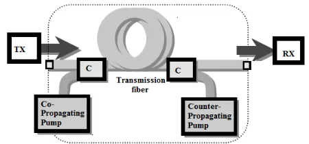
Fiber amplifiers can also be made exploiting the Raman Effect in a fiber medium, which is a nonlinear interaction between photons and atoms of the glass matrix. Raman Effect is a kind of nonlinear interaction which takes place at high powers in an optical medium. It consists of an inelastic photon scattering induced by elementary lattice excitations (i.e., phonons) of the medium. The photon-phonon interaction gives rise to sidebands (Stokes lines) which are shifted from the original frequency by an amount equal to the phonon frequency [1]. A suitable choice of nonlinear medium and pump frequency can give a Stokes line tuned to the frequency of the signal to be amplified. In general, the principal drawback of Raman amplification lies in the type of pump sources needed, because remarkable powers are required to attain the nonlinearity threshold. Raman amplification can also be obtained in a fiber medium with corresponding applications in both second and third windows and even beyond. To illustrate one of these opportunities, it is noteworthy that many countries are using supervisory techniques for telecommunication networks at wavelengths higher than 1600 nm in order not to interfere with service channels. Nowadays the monitoring instrumentation operates with laser diode sources having peak output power on the order of a few tens of milliwatts. The dynamic range of the setup could obviously be increased using more powerful launch pulses. With this aim, Raman fiber amplifiers which can reach output powers of 500 mW in the 1600 nm region have been studied and fabricated [7]. The scheme of such a Raman amplifier is shown in Fig. 2.
231 During Raman scattering, light incident on a
medium is converted to a lower frequency. This is shown schematically in Figure 3. A pump photon νp excites a molecule up to a virtual level (non-resonant state). The molecule quickly decays to a lower energy level emitting a signal photon νs in the process. The difference in energy between the pump and signal photons is dissipated by the molecular vibrations of the host material. These vibration levels determine the frequency shift and shape of the Raman gain curve. Due to the amorphous nature of silica the Raman gain curve is fairly broad in optical fibers. The Figure 4 shows the Scattering diagrams for Stokes and anti-Stokes Raman scattering. An incident photon of frequency ν0 is scattered by a molecule exciting one
quantum of vibrationaly energy Ω and producing a
downshifted scattered photon of frequency νS =ν0
Figure 3: Schematic of the quantum mechanical process taking place during Raman scattering [10].
If the molecule already has vibration energy the incident photon can absorb a quantum of vibration energy producing an up shifted photon of frequency ν
−Ω.
A =ν0
Figure 4: Scattering diagrams for Stokes and anti-Stokes Raman scattering.
Fiber Raman amplification at 1300 nm has only recently been investigated. Such an OFA requires materials having adequate Raman cross sections and a specific fiber design to achieve remarkable power densities inside the fiber core. For these reasons germanium-doped fibers with high numerical aperture, reduced spot size, and low losses are needed. The major problem currently is the unavailability of pump sources capable of emitting ~1 W around 1240 nm, which is the wavelength suited to the generation of a Stokes line around 1300 nm. To overcome this difficulty, the first prototype has been fabricated exploiting the Raman Effect at higher orders. The amplifier is pumped by a device which itself generates the 1240 nm pump radiation through the Raman effect induced from a more convenient spectral region (e.g., 1060 nm from a neodymium-doped fiber laser). As an alternative, the fiber of the Raman amplifier itself was used as a resonant cavity to attain higher-order Raman effects [8]. Both options rely on the technology of grating photo writing into fibers, a technique that has rapidly developed in the last years. These Raman amplifiers exhibit small signal gains around 30 dB and output saturation powers up to +25 dBm, particularly suited for booster applications. Their intrinsic advantage with respect to non-silica OFAs is the use of germane silicate fibers, which allows the application of the usual arc-fusion splice techniques to couple the Raman device to the transmission line. The major disadvantage is complicated design due to the present unavailability of direct pump sources for Raman generation in the second window.
+ Ω.
Both downshifted and up shifted frequencies are observed and called Stokes and anti-Stokes spectral lines.
III. SIMULATION AND DISCUSSION
232
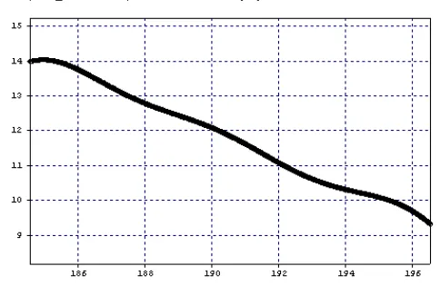
Figure 5 Raman on/off gain for span1
Table1 Raman on/off gain for different spans
Span No.
Maximum Value(dB)
Minimum Value(dB)
Peak to Peak Value(dB)
1 14.7916 9.24445 5.5472
2 14.642 9.25395 5.38805
3 14.5051 9.26555 5.23952
4 14.3912 9.28128 5.10995
5 14.2992 9.29525 5.00392
6 14.2251 9.30698 4.91815
7 14.1668 9.32022 4.84653
8 14.1188 9.32836 4.79045
9 14.0801 9.33734 4.74271
10 14.0483 9.34538 4.70292
From figure 5 and 6 it is concluded that Raman on/off gain curves are almost flat. The flatness of the curves increases as the signal propagates along different spans. From table 1 it is clear that the difference between maximum value and minimum value of Raman on/off gain i.e. peak to peak value is maximum for the first span. Its value is 5.5472dB and it goes on decreasing as the signal propagates from one span to another. The difference between maximum value and minimum value of Raman on/off gain attains a minimum value of 4.70292 dB for the last span. It is also concluded that Raman on off gain is more at lower frequencies (higher wavelengths) as compared to Raman on off gain at higher frequencies (lower wavelengths). This is due to Raman effect that transfers power from signals at lower wavelengths (higher frequencies) to signals at higher wavelengths (lower frequencies).
IV.
CONCLUSION
This paper presents the use of Raman effect for producing a flat gain in a optical communication sysyem. We have used a configuration with 3 pumps at 1430 nm, 1475 nm and 1520 nm with respectively 550 mW, 170 mW and 90 mW is intuitively used to provide a flat gain into a broad bandwidth of about 10 THz. The pump power at lower wavelengths is kept high as compared to pump powers at higher wavelength. This is done due to pump to pump interactions that take place as the pump signals propagate from far end of the fiber towards near end. As the pump signals propagate from far end of the fiber towards near end the pumps at lower wavelengths due to Raman effect amplify the pumps with higher wavelengths.
REFERENCES
[1] F. Tosco (Ed.), CSELT Fiber Optic Communications Handbook, Blue Ridge Summit, PA: McGraw-Hill TAB
Books, 1990. [2] M. Nakazawa, "Soliton Transmission in
Telecommunication Networks," IEEE Commun. Mag., vol. 32, no. 3, pp. 34­p;41. [3] E. Desurvire, Erbium-Doped Fiber Amplifiers. Principles and Applications, New York: Wiley, 1994. [4] T. J. Whitley et al., "Optical Amplifiers and Their Applications," Yokohama, Japan, paper TuA-2, July
4­p;6, 1993.
[5] G. P. Agrawal, N. K. Dutta, Long-Wavelength Semiconductor Lasers, New York: Van Nostrand
Reinhold, 1986. [6] R.C. Alferness, "Optical Amplifiers for Photonic
Circuits," Opt. Ampl. & Their Appl., Santa Fé, NM, June
233 Optical Transmission Lines: Induced Perturbations and
Possible Remedies," Proc. OFC '95, San Diego, CA, Mar. 3, 1995, pp. 181-183. [8] S. G. Grubb et al., "1.3 µm Cascaded Raman Amplifier in Germanosilicate Fibers," Proc. Opt. Ampl. & Their Appl., Breckenridge, CO, Aug. 3­p;5, 1994,
[9] Mohammed N. Islam, ‘Raman Amplifiers for Telecommunications 2 Sub-Systems and Systems’, Springer, New York, 2004.
[10] Clifford Headly, and G. P. Aggarwal, ‘Raman Amplification in Fiber Optic Communication Systems’, Elsevier Academic Press, 2010.
![Figure 3: Schematic of the quantum mechanical process taking place during Raman scattering [10]](https://thumb-us.123doks.com/thumbv2/123dok_us/9787543.1964336/3.612.69.274.255.353/figure-schematic-quantum-mechanical-process-taking-raman-scattering.webp)