A statistical study on the shape and position of the
magnetotail neutral sheet
Sudong Xiao1, Tielong Zhang1,2, Yasong Ge3, Guoqiang Wang1, Wolfgang Baumjohann2, and Rumi Nakamura2 1CAS Key Laboratory of Geospace Environment, University of Science and Technology of China, Hefei, China 2Space Research Institute, Austrian Academy of Sciences, Graz, Austria
3Institute of Geology and Geophysics, Chinese Academy of Sciences, Beijing, China Correspondence to: Tielong Zhang ([email protected])
Received: 2 July 2015 – Revised: 17 January 2016 – Accepted: 10 February 2016 – Published: 26 February 2016
Abstract. We study the average shape and position of the magnetotail neutral sheet based on magnetic field data ob-tained by Cluster, Geotail, TC-1, and THEMIS from the years 1995 to 2013. All data in the aberrated GSM (geocen-tric solar magnetospheric) coordinate system are normalized to the same solar wind pressure 2 nPa and downtail distance X∼ −20RE. Our results show characteristics of the neutral sheet, as follows. (1) The neutral sheet assumes a greater de-gree of curve in the YZ cross section when the dipole tilt in-creases, the Earth dipole tilt angle affects the neutral sheet configuration not only in the YZ cross section but also in the XY cross section, and the neutral sheet assumes a more signif-icant degree of tilt in the XY cross section when the dipole tilt increases. (2) Counterclockwise twisting of the neutral sheet with 3.10◦is observed, looking along the downtail direction, for the positive interplanetary magnetic field (IMF)BY with a value of 3 to 8 nT, and clockwise twisting of the neutral sheet with 3.37◦for the negative IMFBY with a value of−8 to−3 nT, and a northward IMF can result in a greater twist-ing of the near-tail neutral sheet than southward. The above results can be a reference to the neutral sheet model. Our large database also shows that the displaced ellipse model is effective to study the average shape of the neutral sheet with proper parameters when the dipole tilt angle is larger (less) than 10◦(−10◦).
Keywords. Magnetospheric physics (magnetotail)
1 Introduction
The neutral sheet of the magnetotail is located in the middle of the plasma sheet, lying between two lobes (Ness, 1965; Baumjohann and Treumann, 2012). It is characterized by a weak magnetic field, strong cross tail current, and a reversal of the magnetic field direction across it. The neutral sheet is important for the formation of the magnetotail, and the dy-namics of the Earth’s magnetosphere are greatly influenced by physical processes that occur near the neutral sheet. The exact position of the neutral sheet is variable with time. The shape of the neutral sheet is known to be warped because of the tilting of the Earth’s magnetic dipole. Figure 1 illustrates the neutral sheet elliptical shape as controlled by the dipole tilt angle,χ. The dipole tilt is defined as the angle between the Earth’s north dipole axis and theZaxis in the GSM (geo-centric solar magnetospheric) coordinate system and is posi-tive when the north magnetic pole is tilted toward the Sun.
Therefore, it is essential to have a reliable estimate of the average position of the neutral sheet. Several shape models of the neutral sheet are proposed in early studies. For example, a step model is proposed by Murayama (1966), and a stan-dard ellipse model is proposed by Russell and Brody (1967). While the step model stands against theory and observation, the standard ellipse model gives unequal cross-sectional ar-eas for north and south lobes. That would yield different aver-age magnetic field magnitudes in the two lobes, inconsistent with the observations.
tilt angleχ. The hinging point is indicated in this figure, and the hinging distanceH0is the distance from the Earth’s center to the hinging point, as shown in this figure.
ellipse neutral sheet model as shown in Fig. 2, given by
Z=
"
(H0−D) s
1− Y 2
Y02 −D
#
sinχ |Y|< Y0
−Dsinχ |Y| ≥Y0
, (1)
whereH0is the magnetotail hinging distance from the Earth to the hinge point shown in Fig. 1, D is a factor of the displacement of ellipse, and Y0 is the semi-major axis of the model ellipse, as Fig. 2 shows. This model accounts for asymmetrical areas of north and south lobes via a displace-ment along Z. For eliminating the aberration effect caused by the Earth’s orbital motion, also called the windsock effect, all data were rotated to the aberrated GSM (AGSM) coordi-nate system. The AGSM coordicoordi-nate system has its X axis antiparallel to the average direction of the solar wind, aber-rated from the Sun–Earth line. As with the GSM coordinate system, the XY plane contains the Earth magnetic dipole axis with aZaxis chosen to be in the same sense as the northern magnetic pole, and the Y axis completes the right-handed Cartesian coordinate system.
Similar to Fairfield (1980), Hammond et al. (1994) also chose the displaced ellipse neutral sheet model and the AGSM coordinate system, but with a more exact aberra-tion angle of 4◦. In addition, all data in the magnetosphere were normalized to the same solar wind dynamic pressure (3.8 nPa) using OMNI solar wind data with the equation of R, the magnetotail radius, given as
R∝P− 1 6
obs, (2)
and a cross section (X= −25RE)given by the flaring mag-netopause model equation of Howe Jr. and Binsack (1972) as
R∝arctan r
10−XAGSM 15.9
!
. (3)
sheet. The parameters of the model are marked in this figure and “−Dsinχ” is the displaced degree.
Different from Fairfield (1980), Hammond et al. (1994) counted data to bins on a cross section, and then obtained parameters via fitting the points where the X component of the magnetic field changes sign. Tsyganenko and Fair-field (2004) developed an analytical approximation for the shape of the nightside tail current sheet with a semi-empirical model as a function of the Earth’s dipole tilt angle, solar wind ram pressure, and the interplanetary magnetic field (IMF). The model of Tsyganenko and Fairfield (2004) was devel-oped for covering a downtail distance from 0 to 50RE, con-taining the region of the dipolar magnetic field.
The shape of the neutral sheet can be greatly affected by the solar wind parameters, the IMF, and the dipole tilt an-gle (Russell, 1972; Sibeck et al., 1985; Tsyganenko and Fair-field, 2004). Russell (1972, 1973) predicted that the IMFBY can twist the magnetotail neutral sheet. Sibeck et al. (1985) found that the neutral sheet can be twisted left- or right-handed by the positive or negative IMFBY, respectively. Fur-ther observations found that a northward IMF can result in a greater twisting (e.g., Owen et al. 1995). Later, Tsyganenko and Fairfield (2004) found that an increase in solar wind dy-namic pressure results in a decrease in the hinging distance H0. Recently, based on the model of Tsyganenko and Fair-field (2004), Tsyganenko et al. (2015) developed a new quan-titative model of the shape of the magnetospheric equatorial current sheet as a function of the dipole tilt angle, solar wind dynamic pressure, and IMF, and the model covers all local time, including the dayside sector.
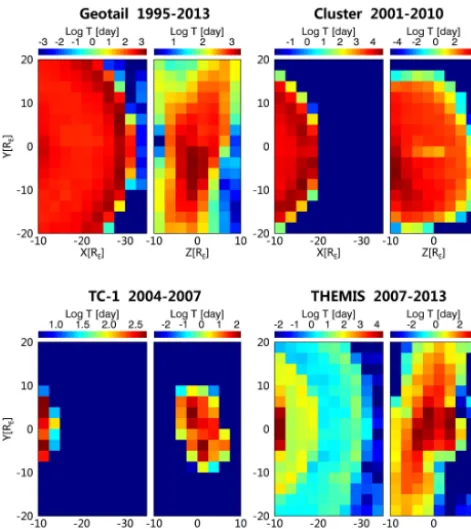
[image:2.612.326.526.66.214.2] [image:2.612.51.283.70.167.2]Figure 3. Orbital coverages of Geotail during the 19-year (1995–
2013) tail period, Cluster 1–4 during the 10-year (2001–2010) tail period, TC-1 during the 4-year (2004–2007) tail period, and THEMIS P1–P5 during the 7-year (2007–2013) tail period. The bin size is 2.5RE×2.5RE. In each group, the left image indicates the orbital coverage in the XY plane and the right panel indicates the or-bital coverage in the ZY plane. The residence times of the satellites are given in days.
2 Data and methods
More data and satellites have become available since the work of Tsyganenko and Fairfield (2004). In total, 10 years (2001–2010) of Cluster 1–4 (Balogh et al., 2001), 19 years (1995–2013) of Geotail (Kokubun et al., 1994), 4 years (2004–2007) of TC-1 (Carr et al., 2005), and 7 years (2007– 2009 for P1/P2; 2007–2013 for P3–P5) of THEMIS (Auster et al., 2008) magnetometer data are used in our study, with an original resolution of 4, 64, 60, and 3 s, respectively. The data from Cluster and THEMIS are averaged over 1 min in-tervals. In addition, the concurrent solar wind and IMF data from OMNI (5 min resolution) are combined to normalize the magnetotail neutral sheet model. To obtain symmetric im-ages, the data are converted into the AGSM coordinate sys-tem with an average aberration angle of 4◦.
[image:3.612.50.286.66.331.2]This work focuses on the near-Earth and middle tail. The hinging distance can serve as an indication of the range of the dipolar magnetic field of the Earth. Based on prior stud-ies, the hinging distance is less than 10RE, so we consider the area with a downtail distance beyond 10RE. Further-more, in consideration of the satellite orbits, the observation
Figure 4. Orbital coverage of all satellites in the XY and ZY plane
in the AGSM coordinate system. The bin size is 2.5RE×2.5RE. The left panel indicates the orbital coverage in the XY plane and the right panel indicates the orbital coverage in the ZY plane. As this figure shows, a better coverage in space and time can be obtained by merging the data of different satellites.
region is set as−35RE<X<−10RE,−20RE<Y< 20RE, and−10RE<Z< 10RE(in AGSM, which is used through-out the paper unless mentioned otherwise). Figure 3 shows orbit coverage of the magnetic field data obtained from Geo-tail, Cluster, TC-1, and THEMIS satellites projected onto the XY and YZ plane with bin size 2.5×2.5RE. One can find that THEMIS and Geotail have a large number of data and extensive spatial coverage. Cluster provides a large number of data, but the coverage is concentrated in the area with a near-to-middle tail distance. The orbit of TC-1 is lower than Cluster, providing more data nearer to the Earth.
In order to combine all data from different satellites to study the average shape and position of the neutral sheet, the data should be merged into one unified data set. Similar to Fig. 3, the unified data set is plotted in the XY (left panel) and YZ (right panel) plane. As shown in Fig. 4, combining the data from different satellites provides better coverage, in space and time.
downtail distance with the magnetopause model of Howe Jr. and Binsack (1972). Considering the data distribution from X∼ −10REtoX∼ −35RE, a reference value of a downtail distance of 20REis chosen in this study.
The next step is to obtain images of the cross section of the magnetotail containing the average shape and position of the neutral sheet. In order to investigate the effect of the dipole tilt on the neutral sheet, the data are divided into 14 sets with a dipole tilt angle interval of 5◦. Magnetic field data in each set are binned into 0.5×0.5REbins in a plane of|Y|< 20RE and|Z|< 10RE. Bins are ignored if they contain fewer than 10 data points. We count the number of data with a positive BXin each bin and calculate the percentage. A percentage of more than 50 % indicates thatBXin the corresponding bin is positive, and a percentage of less than 50 % indicates a negativeBX.
3 Global shape of the magnetotail neutral sheet
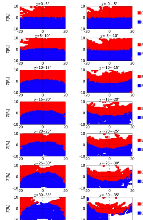
[image:4.612.52.282.64.140.2]Figure 6 shows the shape of the neutral sheet under differ-ent dipole tilt angle. Red indicates that BX is positive and blue indicates negative BX. The position between the two colors is considered the neutral sheet. As Fig. 6 shows, the neutral sheet is curved more with increasing dipole tilt. The neutral sheet curves toward north for positive dipole tilts and toward south for negative dipole tilts. The correlation be-tween the dipole tilt and the curvature of the neutral sheet can be expressed as a sine function. The points where the sign of BXchanges are recorded in Fig. 7, and the points where data are lacking are ignored. Our study focus on the average shape and position of the neutral sheet; therefore an empiri-cal model of the displaced ellipse model is chosen to fit the shape of the neutral sheet. The average position and shape of the neutral sheet can be parameterized by fitting these points using the displaced ellipse model. The fitted curves are also plotted in Fig. 7. We calculate the correlation coefficient (R2) for each best-fitted curve, labeled on each panel.
Figure 6. The sign ofBX(in AGSM) in 0.5RE×0.5REbins for a 40RE×20REYZ cross section in 5◦intervals of dipole tilt angle. All data are normalized toX= −20REand a solar wind dynamic pressure of 2 nPa. Red (blue) indicates more positive (negative) val-ues ofBXin each bin. The neutral sheet is located between the red and blue areas.
Figure 8 shows the neutral sheet configuration in the XY cross section with the data of−5RE<Y< 5RE. The fitting angle of slope and the uncertainty are labeled. While the neu-tral sheet has a displacement alongZ, it tilts slightly along the tailward direction when the dipole angle increases. The larger the dipole tilt angle is, the more the neutral sheet tilts. Therefore, the dipole tilt angle affects not only the neutral sheet warping in the YZ cross section but also the tilting of the neutral sheet in the XY cross section.
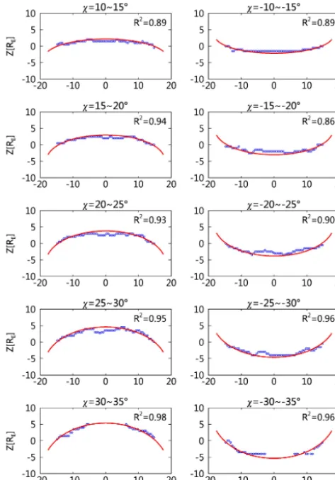
[image:4.612.310.547.66.431.2]Figure 7. Fitting the neutral sheet locations in the YZ cross sections
for different dipole tilt angles. The blue points give the positions BX=0 (in AGSM), and the red lines are the best fits to these points.
The parameters listed in Table 2 have been normalized to eliminate the effect of solar wind dynamic pressure and mag-netotail flaring. Thereby, the model function contains a scal-ing factor as follows:
Z=
"
H00+D0 s
1− Y 2
Y002 −D0
#
sinχ |Y|< Y00
−D0sinχ |Y| ≥Y0
0, (4)
H0=9.98, Y0=18.44, D=15.10, (5)
H00=H0·ksp, Y00=Y0·ksp·kmf, D0=D·ksp, (6)
ksp=
2 Pobs
1/6
, kmf=1.06 arctan
r
10−XAGSM 15.9
!
[image:5.612.48.288.521.690.2], (7) where H00,Y00, andD0 are the three parameters of the dis-placed ellipse model. The parameters of kspandkmfare the
Figure 8. An illustration of the neutral sheet in the XY cross section
for 5◦intervals of dipole tilt angle. Data of−5RE<Y< 5RE are chosen. To increase the data coverage, the negative dipole tilt angle data are combined with the positive angle data, and the data for a tilt greater than 25◦are combined also. The ratio of theZ axis to theXaxis in data units is set as 2.
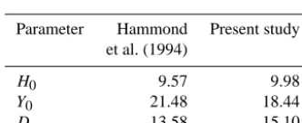
Table 2. Final parameters of the displaced ellipse model of the
neu-tral, with a downtail distance of 20RE and a solar wind dynamic pressure of 2 nPa.
Parameter Hammond Present study et al. (1994)
H0 9.57 9.98
Y0 21.48 18.44
D 13.58 15.10
A comparison with three prior studies is given in Fig. 9. All model curves are shown for a dipole tilt of 30◦. The
re-sult of this study is shown by the blue line. The green, red and brown lines indicate the models of Fairfield (1980), Ham-mond et al. (1994), and Tsyganenko and Fairfield (2004), re-spectively. Except for the model of Fairfield (1980), which did not consider the effect of solar wind dynamic pressure and downtail distance, the other three models are shown for a downtail distance of 20REand a solar wind dynamic pres-sure of 2 nPa. As Fig. 9 shows, at the center, where theY axis value is zero, the height of the neutral sheet in this study is close to the prior models, a little lower than Fairfield (1980) and a little higher than Hammond et al. (1994) and Tsy-ganenko and Fairfield (2004). The difference becomes less when the dipole tilt decreases. Our hinging distance is a little greater than that of Hammond et al. (1994) and less than that given by Fairfield (1980). Our result is very similar to the result of Tsyganenko and Fairfield (2004), which indicates that the displaced ellipse model with suitable parameters are reliable to study the average of the neutral sheet shape. 4 IMF dependence of the magnetotail neutral sheet
The IMF has a bearing upon the shape of the neutral sheet (Russell, 1972, 1973). The IMF BY can lead to a twisting of the magnetotail (Cowley, 1981), as well as the neutral sheet. The IMFBY-related twisting effect has been observed in prior studies (e.g., Slavin et al., 1983; Sibeck et al., 1985).
[image:6.612.79.259.107.240.2]from three previous studies and this study are shown for a dipole tilt of 30◦. The blue line shows the result of this study. The green line indicates the model of Fairfield (1980). The red line indicates the model of Hammond et al. (1994). The brown line, which is close to the blue line, represents the model of Tsyganenko and Fair-field (2004). Except for FairFair-field (1980), the neutral sheet models are shown with a downtail distance of 20REand a solar wind dy-namic pressure of 2 nPa.
Figure 10. Illustration of the IMF-BY related twisting effect on the neutral sheet for (a) IMF-BY<−3 nT, (b)−1 nT < IMF-BY< 1 nT, and (c) IMF-BY> 3 nT. The white belt between red and blue indi-cates the shape of the neutral sheet. The black dotted lines are the fit-ting results of the neutral sheet, and the twisfit-ting angles are marked in the respective panel. In order to obtain a more pronounced visual effect, the ratio of theZaxis to theY axis in data units is set as 2. It is shown that a counterclockwise (clockwise) twisting of the neutral sheet is observed, along the downtail direction, when the IMF-BY is positive (negative).
Previous works (e.g., Owen et al., 1995; Maezawa and Hori, 1998) have also found that the IMFBY-related twisting be-comes much larger during the periods of northward IMF.
In order to show a flat neutral sheet, only data with a low dipole tilt angle (absolute value less than 5◦) are used. To
[image:6.612.85.251.300.368.2] [image:6.612.310.547.350.436.2]IMP-8 ISEE-2 OMNI
ACE WIND IMP-8
TC-1 THEMIS 1–5 OMNI
Magnetic field data
IMP-6
1971–1973 9–12 IMP-7
1972.10–1973.3 IMP-8
1973.11–1974.11
IMP-7 1973 IMP-8 1978–1986 ISEE-2
1978/1979/1984/1986
Geotail 1994–2002 Polar 1999–2001
Cluster 1–4 2001–2010 Geotail 1995–2013 TC-1 2004–2007 THEMIS P1–P2 2007–2009 P3–P5 2007–2013
Solar wind data No OMNI ACE
WIND IMP-8
OMNI
Scaling No Solar wind dynamic
pressure
Flaring of the magneto-tail
No Solar wind dynamic pressure
Flaring of the magneto-tail
Model The displaced ellipse model
The displaced ellipse model
A semi-empirical model
The displaced ellipse model
Obtaining parameters
Minimizing the number of mismatches between the observed and pre-dicted orientation of the magnetic field on two sides of the model
Fitting the points between bins with different sign ofBX
Minimizing the number of mismatches between the observed and pre-dicted orientation of the magnetic field on two sides of the model
Fitting the points between bins with different sign ofBX
Coordinate system AGSM AGSM GSW AGSM
red and blue area indicates the shape of the neutral sheet. As expected, looking along the downtail direction, the neutral sheet is twisting clockwise for a negative IMFBY and coun-terclockwise for positive IMFBY. Here we find a clockwise twist of 3.37◦ for the IMFBY between−8 and−3 nT and a counterclockwise twist of 3.10◦ for the IMFBY between
3 and 8 nT. Furthermore, the IMF BZ also plays a signifi-cant role in the neutral sheet twisting. As shown in Fig. 11, we separate Fig. 10a and c into positive and negative IMFBZ periods. For the IMFBYbetween−8 and−3 nT, one can find a clockwise twist∼4.40◦for positive IMFBZ, and∼2.73◦ for negative IMFBZ; for the IMFBY between 3 and 8 nT, a counterclockwise twist∼3.37◦is found for positive IMF BZ, and∼2.20◦for negative IMFBZ. This indicates that a northward IMF can result in a greater twisting of the neutral sheet in the near tail.
5 Discussion and conclusions
Our results show that the displaced ellipse model of the neu-tral sheet has a greater degree of curve than that of Ham-mond et al. (1994) and is close to the model of Tsyganenko and Fairfield (2004). The position of the hinging point in this study is close to the findings in the prior studies (Hammond et al., 1994; Tsyganenko and Fairfield, 2004). As shown in Fig. 9, the curves in the cross section of YZ are plotted with a very large dipole tilt of 30◦ to make the difference clearer. The curves will be closer to each other for a smaller dipole tilt. Fairfield (1980) did not normalize the data, which have a significant effect on the result, so the curve of Fair-field (1980) is just for reference.
[image:7.612.59.537.85.508.2]satel-Figure 11. Illustration of the IMF-BZ effect on the neutral sheet twisting for (a1) IMF-BY<−3 nT and IMF-BZ> 0 nT, (b1) IMF-BY> 3 nT and IMF-BZ> 0 nT, (a2) IMF-BY<−3 nT and
IMF-BZ< 0 nT, and (b2) IMF-BY> 3 nT and IMF-BZ< 0 nT. It is shown that a northward IMF can result in a larger twisting angle of the near-tail neutral sheet.
lites have become available and more data can be obtained. We define a satellite year as the number of years of data. However, satellites with similar orbits are counted only once. For this study, the four Cluster satellites count as one, and THEMIS P3–P5 should be counted as one, too. Thereby, our study spans 46 satellite years, containing 10 years of Clus-ter, 19 years of Geotail, 4 years of TC-1, and 3+3+7 years of THEMIS (compared with 9 satellite years in the study of Fairfield, 1980, 14 satellite years in the study of Hammond et al., 1994, and 12 satellite years of Tsyganenko and Fairfield, 2004). As in the investigations of Fairfield (1980) and Ham-mond et al. (1994), the data are converted to the AGSM coor-dinate system in this work. Tsyganenko and Fairfield (2004) converted the data to the GSW (geocentric solar wind) co-ordinate system. The difference between the AGSM coordi-nate system and the GSW coordicoordi-nate system is the direction of theXaxis. TheXaxis in the AGSM coordinate system is antiparallel to the average solar wind flow, while theXaxis in the GSW coordinate system is antiparallel to the observed solar wind flow.
The effect of solar wind dynamic pressure and magneto-tail flaring on the shape of the neutral sheet is substantial. Thus all data are scaled to the same solar wind dynamic pressure and downtail distance to eliminate their effects. We use a statistical method to investigate the average position of the neutral sheet with grids (bins) in the YZ cross section, instead of simply recording where the X component of the magnetic field changes sign. The bin method offers a superb solution to solve the problem of undersampling and increases the accuracy of the result. Fairfield (1980) parameterized the model by minimizing the number of mismatches between the
the neutral sheet has a displacement alongZwith curving. In this investigation, we find that the dipole tilt angle has a global influence on the neutral configuration. It affects not only the warping of the neutral sheet in the YZ cross sec-tion but also the tilting in the XY cross secsec-tion. Furthermore, we observe the IMFBY twisting effect on the neutral sheet. As shown in Fig. 10, the neutral sheet twists clockwise for a negative IMFBY and counterclockwise for a positive IMF BY. It is considered that the farther the distance from Earth, the larger the degree of the IMFBY twisting (Cowley, 1980; Tsyganenko and Fairfield, 2004). The IMFBY twisting ef-fect in the distant magnetotail has been observed in some prior studies (Slavin et al., 1983; Sibeck et al., 1985; Owen et al., 1995; Maezawa and Hori, 1998). In this study, the ob-servation of the IMFBY twisting effect focused on the near tail, betweenX= −10RE and−35 RE. It is observed that the larger the IMFBY, the larger the twisting angle. How-ever, because of the lack of data for large IMFBY, it could not be accurate enough to investigate the quantitative relation between the twisting angle and the IMFBY in this observa-tion. In the near tail, we can also observe a larger twisting angle for northward IMFBZ than for southward, as which has been observed in the distant tail (e.g., Owen et al., 1995; Maezawa and Hori, 1998).
[image:8.612.49.284.63.250.2]for the data used in this study. The TC-1 FGM and PGP data were provided by the Austrian DSP Data Center at http://dione. iwf.oeaw.ac.at/ddms/, and the Geotail MGF data and the interplan-etary data of OMNI were obtained from CDAWeb online facility at http://cdaweb.gsfc.nasa.gov/.
The topical editor, C. Owen, thanks H. Lühr and one anonymous referee for help in evaluating this paper.
References
Auster, H. U., Glassmeier, K., Magnes, W., Aydogar, O., Baumjo-hann, W., Constantinescu, D., Fischer, D., Fornacon, K., Georgescu, E., Harvey, P., Hillenmaier, O., Kroth, R., Ludlam, M., Narita, Y., Nakamura, R., Okrafka, K., Plaschke, F., Richter, I., Schwarzl, H., Stoll, B., Valavanoglou, A., and Wiedemann, M.: The THEMIS fluxgate magnetometer, Space Sci. Rev., 141, 235–264, doi:10.1007/s11214-008-9365-9, 2008.
Balogh, A., Carr, C. M., Acuña, M. H., Dunlop, M. W., Beek, T. J., Brown, P., Fornacon, H., Georgescu, E., Glassmeier, K.-H., Harris, J., Musmann, G., Oddy, T., and Schwingenschuh, K.: The Cluster Magnetic Field Investigation: overview of in-flight performance and initial results, Ann. Geophys., 19, 1207–1217, doi:10.5194/angeo-19-1207-2001, 2001.
Baumjohann, W. and Treumann, R. A.: Basic Space Plasma Physics (Revised Edition), Imperial College Press, London, UK, 2012. Carr, C., Brown, P., Zhang, T. L., Gloag, J., Horbury, T., Lucek,
E., Magnes, W., O’Brien, H., Oddy, T., Auster, U., Austin, P., Aydogar, O., Balogh, A., Baumjohann, W., Beek, T., Eichel-berger, H., Fornacon, K.-H., Georgescu, E., Glassmeier, K.-H., Ludlam, M., Nakamura, R., and Richter, I.: The Double Star magnetic field investigation: instrument design, performance and highlights of the first year’s observations, Ann. Geophys., 23, 2713–2732, doi:10.5194/angeo-23-2713-2005, 2005.
Cowley, S. W. H.: Magnetospheric asymmetries associated with the y-component of the IMF, Planet. Space Sci., 29, 79–96, 1981. Fairfield, D.: A statistical determination of the shape and position
of the geomagnetic neutral sheet, J. Geophys. Res., 85, 775–780, doi:10.1029/JA085iA02p00775, 1980.
Hammond, C. M., Kivelson, M. G. and Walker, R. J.: Imaging the effect of dipole tilt on magnetotail boundaries, J. Geophys. Res., 99, 6079–6092, doi:10.1029/93JA01924, 1994.
IMF Dependence, and Thermal Properties, in New Perspectives on the Earth’s Magnetotail, American Geophysical Union, Wash-ington, D.C., USA, 1–19, doi:10.1029/GM105p0001, 1998. Murayama, T.: Spatial distribution of energetic electrons in
the geomagnetic tail, J. Geophys. Res., 71, 5547–5557, doi:10.1029/JZ071i023p05547, 1966.
Ness, N. F.: The Earth’s magnetic tail, J. Geophys. Res., 70, 2989– 3005, doi:10.1029/JZ070i013p02989, 1965.
Owen, C. J., Slavin, J. A., Richardson, I. G., Murphy, N., and Hynds, R. J.: Average motion, structure and orientation of the distant magnetotail determined from remote sensing of the edge of the plasma sheet boundary layer with E >35 keV ions, J. Geophys. Res.-Atmos., 100, 185–204, doi:10.1029/94JA02417, 1995.
Russell, C. T.: The configuration of the magnetosphere, in: Critical Problems of Magnetospheric Physics, edited by: Dyer, E. R., p. 1, IUCSTP Secretariat, National Academy of Sciences, Washington DC, USA, 1972.
Russell, C. T.: Comments on the paper “The internal structure of the geomagnetic neutral sheet”, by K. Schindler and N. F. Ness, J. Geophys. Res., 78, 7576–7579, doi:10.1029/JA078i031p07576, 1973.
Russell, C. T. and Brody, K. I.: Some remarks on the position and shape of the neutral sheet, J. Geophys. Res., 72, 6104–6106, doi:10.1029/JZ072i023p06104, 1967.
Sibeck, D. G., Siscoe, G. L., Slavin, J. A., Smith, E. J., Tsurutani, B. T., and Lepping, R. P.: The distant magnetotail’s response to a strong interplanetary magnetic field By: Twisting, flatten-ing, and field line bendflatten-ing, J. Geophys. Res., 90, 4011–4019, doi:10.1029/JA090iA05p04011, 1985.
Slavin, J. A., Tsurutani, B. T., Smith, E. J., Jones, D. E., and Sibeck, D. G.: Average configuration of the distant (<220 Re) magneto-tail: Initial ISEE-3 magnetic field results, Geophys. Res. Lett., 10, 973–976, doi:10.1029/GL010i010p00973, 1983.