Humanoid Robot Cooperative System by Machine Vision
https://doi.org/10.3991/ijoe.v13i12.7594Robinson Jiménez Moreno, Oscar Fernando Aviles!!"
Militar Nueva Granada University, Bogotá, Colombia
Ruben Darío Hernández
Piloto de Colombia University, Bogotá, Colombia
Abstract—This article presents a supervised control position system, based on image processing and oriented to the cooperative work between two human-oid robots that work autonomously. The first robot picks up an object, carry it to the second robot and after that the same second robot places it in an endpoint, this is achieved through doing movements in straight line trajectories and turns of 180 degrees. Using for this the Microsoft Kinect , finding for each robot and the reference object its exact spatial position, through the color space conver-sion and filtering, derived from the information of the RGB camera that counts and obtains this result using the information transmitted from the depth sensor, obtaining the final location of each. Through programming in C #, and the de-veloped algorithms that allow to command each robot in order to work together for transport the reference object, from an initial point, delivering this object from one robot to the other and depositing it in an endpoint. This experiment was tested performed the same trajectory, under uniform light conditions, achieving each time the successful delivering of the object.
Keywords—Cooperative control, fuzzy logic, image processing, robot control, 3D vision and stereo.
1
Introduction
In the last decades, the robotic systems and robot control techniques have evolved significantly. The development of actuators and sensors that increase in greater com-plexity as much the robotic structure as the control autonomy of the robot. Among the more advanced structures are the humanoid type and among more advanced the tech-niques of supervision and control are machine vision systems and the intelligent algo-rithms, which give rise to cognitive robotics [1], for the latter case are outstanding Neural networks and fuzzy logic.
human face. In the first, an application on an android robot, allows the robot to repli-cate the tracking of the view that a person uses when interacting with a group. In the second, the skin detection algorithm is added to segment the hands and teleoperated to robotic arm.
An industrial application based on the control of a delta robot, using machine vi-sion algorithms, is presented in [5], the robot can take from one conveyor belt, objects in disorder and order them in another band. In [6] a machine vision system is used to identify specific objects to be manipulated by a robotic arm managed by a computer brain interface. In [7] is presented a robotic arm controlled using a machine vision system, which includes learning by reinforcement, implementing neural networks.
In [8] a quality inspection system is developed in which, through stereo vision, it is sought to expose the entire piece to be evaluated directly, with the cameras, avoiding obstacles and occlusion of the object by rotation. In [9], a stereo vision system is presented along with a force feedback system, which is used to know the spatial inter-action of a robotic manipulator with the medium in which it works.
In [10] a trajectory planning system is presented to replicate an image through a robotic system, using image processing algorithms, where the identifier is a deter-mined set, which is followed as a path by the Robot, extending the possibility of ap-plications to laser cutting systems, for example.
In [11], a path prediction method is used to achieve the displacement of a human-oid type robot, to visually follow a moving object and to move to its final position in a reduced trajectory.
Previously was showed the state of the art to establish control strategies for robots, through machine vision systems that depends on decision systems, generally support-ed by techniques of artificial intelligence such as fuzzy logic.
This article covers the development of a control algorithm for two robotic human-oid agents, working together under the supervision of a machine vision system, which generates autonomy for the interaction between robotic agents. A control system of the position of the robotic agents, for move reference object between localizations, contributing to the state of art a fuzzy position controller, a 3D vision system using Kinect and the collaborative manipulation between two robotic humanoid agents, which together have not been widely developed. Previous work developed by the group and that serve as a basis for the replica of the present work are exposed in [13-15], Previous works with the same control objective are not found in the state of the art under the proposed machine vision system..
The following article describes the algorithms used for the identification of each robotic agent and the reference object, in the section 2, in the section 3 we present a fuzzy controller for control the results obtained and finally in the section 5 the conclu-sions. Position of the robotic agents, in section 4 are presented
2
Machine vision system
iden-tify each robot spatially to control the displacement. The identification system is based on the Microsoft Kinect, which has an infrared projector that generates a grid pattern captured by a camera of the same type, through this function is possible gen-erate a depth map that relates the distance between the objects and the Kinect, within its range of operation. Also the Kinect has a RGB camera, with a resolution of
!"#$!!"#$ pixels, where the color information is obtained. These two tools of the
Kinect are used for the detection of each robot and the object of reference.
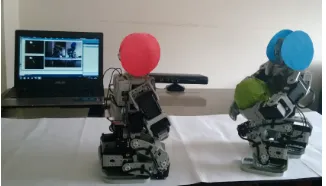
Fig. 1. Application environment
For the case, of the color information is located each robotic agent by a circular identifier in the head of each of them. For each identifier, was used image processing algorithms to differentiate the color of both robots. For the first one, a was used a red circle and the for the second one was used a blue circle. The green ball that is the reference object, is also identified by a color identification algorithm.
To filter the colors that allow to discriminate each robot in the image, a color trans-formation is used to emphasize to each tonality in the space, the red one and the blue one. In this case the transformation from RGB to !!!!!, this transformation takes each !! and !! components separately, as result the blue and the red color are high-lighted. In Eq. (1) to Eq. (3) are illustrated the equations that allow to obtain the trans-formation between the described color spaces. The reference object is filtered from the ! component of the original color space.
! !! !! ! ! !!!"" ! ! ! !!!"#! ! ! !!!!" ! ! (1)
!"! ! ! ! (2)
!" ! ! !! (3)
The component !! as the component !!, are thresholds in order to filter only the circles that discriminate each robot, eliminating any other element of the image. In Eq. (4) the method of thresholding is shown, where Utl corresponds to the lower threshold and Uth to the upper threshold, the pixels below and above the respective thresholds are set to black and the range of intermediate pixels left blank, these Last will correspond to the circular area.
These thresholds were determined by finding only the desired hue. For the refer-ence object, the same threshold was used, but with respect to the component !, of the RGB space.
The thresholding leaves some contours of the robot in the image. To eliminate it, an opening morphological operation is applied, defined by Eq. (5). First a morpholog-ical erosion operation is carried out, that reduces the area of all white pixels, followed for a dilation operation, which restores all those pixels that did not disappear in the previous operation, in this case all that is not the red or a blue. These operations uses a square structuring element of size !!!.
!!! ! ! ! ! ! ! (5)
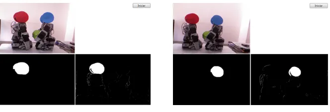
In Figure 2 we can see the result of the red color discrimination, where the image captured by the Kinect, the unification with noise and the result of the opening opera-tion are observed.
In Figure 3, the result of the same image processing operation is seen, but oriented towards the detection of the blue circle. Respectively, the low threshold (Utl) and the high (Uth) were 185 and 202 for red and 198 and 216 for blue.
Fig. 2. Red circle detection Fig. 3. Blue circle detection.
The sensor depth camera with the SDK developed by the manufacturer allows to obtain its information by programming, delivering the data in the form of a byte type array, where the depth value of each pixel of the image is represented by 13 Bits, thus requiring two bytes to store it, in which the first bits represent the depth directly in millimeters. Access to this information is made keeping in mind that there is only one channel, which implies a three-bit shift to access the depth measurement between pixels. For the case, an index is used that determines which is the pixel in the image of which it is wanted to know the distance Eq. (6).
!"#!$%! !"#$%! ! ! !"#$%&! !"#$% !!"#$%! ! (6)
!"#$% ! !""!#$%&'(!!"#$%! ! ! (7)
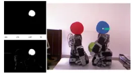
In Figures 4 and 5 show the finished image processing for the spatial location of each robotic agent, identifying the distance to each one.
Fig. 4. Distance detection of the red robot Fig. 5. Distance detection of the blue robot.
3
Fuzzy position controller
The problems of friction against the floor, during the displacement of the robotic agent, presents variations in the same trajectory, as can be seen in [9]. In this case, each robot must rotate on its own axis and then move in a straight line. According to Figure 6, robot one will take the reference object (OPI) from an initial position PIR1, after this it will rotate 180 degrees (GIT) and move in a straight line (TR1) to the second robot located in position PIR2, It will deliver the object to you and will rotate back 180 degrees back to its starting position (GR). The second robot, which now has the object, will rotate 180 degrees (GIT) to continue in a straight line (TR2) to the object's final position (OPF), deposit it and rotate 180 degrees in return (GR) to its position (PIR2).
Fig. 6. Trajectories to follow.
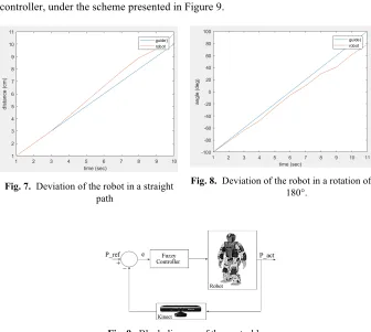
The figure 7 shows the deviation presented by the robot in one of the straight-line tests.
Because both robots must follow straight trajectories and rotate 180 degrees, it is required to control the position of each against of the deviations presented, or they will never intersect each other to move the object from the initial position to the final position. To solve this problem, a diffuse position controller is implemented.
Because humanoid robots employ intelligent servomotors, which receive a speed parameter and a position parameter, they are shown by a fuzzy proportional derivative controller, under the scheme presented in Figure 9.
Fig. 7. Deviation of the robot in a straight path
Fig. 8. Deviation of the robot in a rotation of 180°.
Fig. 9. Block diagram of the control loop
Where the position error, seen as the difference between the position in which the robot should be and the real position, is shown in Eq. (8).
! ! !
!"#!
!
!"#(8)
This error is calculated in two ways, the first one when the robot is in the straight path, in which the error is determined by the difference between the depth measured by the Kinect, with respect to the central pixel of the circumference and the depth that should be, which is a straight line so is constant.
!"# !
!!"
!
!(9)
If the robot has completely rotated 180 degrees, the roundness value will be 1, but a smaller value will be obtained inversely proportional to the angular error from the final position in which the robot stopped.
The rule base used for the fuzzy controller for the position during the straight path is shown in Table 1. Table 2 show the rule base for the fuzzy controller. Where Z corresponds to zero error, N to negative, P to positive, M to medium, A corresponds to high and B to low. So is possible to have a negative error low (NB) or positive high (PA)
Table 1. Diffuse rules for the straight path. d
e\e A N M N B N Z B P M P A P N
A A I A I A I B I B I B I Z N
M A I M I B I M I B I Z B D N
B A I B I M I B I Z B D B D Z B I M I B I Z B D M D B D P
B B I B I Z B D M D A D A D P
M B I Z B D M D B D M D A D P
A Z B D B D B D A D A D A D
Table 2. Diffuse rules for the 180 turn. d
e\e A N B N Z B P A P N
A A I A I B I B I Z N
B A I A I B I Z B D Z B I B I Z B D B D P
B B I Z B D M D A D P
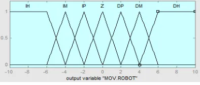
Because a 90-degree error would mean zero roundness, which corresponds to the maximum error, membership functions were limited to the range -90 to 90 for turn, from -100 to 100 mm for a straight path, as illustrated in Figure 10.
(a) Straight trajectory (b) Rotating trajectory.
Fig. 10.Fuzzy sets for error in: (a) (b)
Figure 11 output of the membership functions.
Fig. 11.Fuzzy set for the output.
It was decided to use the ruspinni partition in this way to obtain a value of one generating a better control of the movement. Also, the defuzzification method used corresponds to the center of gravity method [2], because it allows to better balance the output value with respect to the activation of the corresponding rules. In Eq. (10) is shown the way of obtaining the fuzzy output value
!
!
!
!!!!
!!
!
!! !!!
!
!!!!!
!!
!!!!
(10)
4
Results
loading the program into the microcontroller and for verifying the movements, the communication protocol Wireless Zegbee.
The system allowed to monitor the movement of each robotic agent separately as the reference was detected. The coordination of actions allowed to move the object from one site to another through the collaboration between the two robots. The action was performed correctly eight of the ten times, the error presented was presented during the final coordination in third and seventh attempt, because the final position of the robot one and the initial position for the two robot did not coincide to deliver the object. This was caused by strong movements in the turn (changes of more than 10 degrees), in order to avoid these drawbacks, was applied a linear regression algo-rithm, described by Eq. (11). Then the new movement trends are obtained, improving the stability in the rotation, so the angle no longer changes sharply from one value to another, therefore the value of change now is more gradual. For example, from an angle of rotation of an average of 10 degrees, one went to obtain one of 6 degrees, reducing what for the case is called the angle of deviation or error in steady state.
! ! !
!!!!!!
!!
!!!
!
!! !!!
!!!
! !!
!!
!!!
(11)
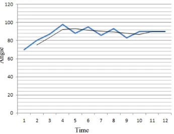
Using this linear regression and fuzzy controller, the robot was able to rotate the expected 90 degrees. Figure 12 shows the change presented to the controller response, with and without linear regression. It is observed that without the regression the con-troller takes the angular position of the robot with more sudden changes, which in the two occasions did not allow the transfer of the object, with the regression the slow change leaves the robot always in the correct location.
Fig. 12.Correction of the robot´s angular position
opera-tion, with the detection of both robots, in a process of turning the robot with blue mark to align with the robot of red mark.
Fig. 13.Cooperation between robots.
5
Conclusions
We achieved implement an algorithm to control robotics agents using machine vi-sion techniques, setting the cooperative action between two robots agents effectively.
Due to the complex kinematics of robots, implementing a control algorithm using fuzzy logic proves to be an effective strategy, fast and with low computational over-head.
Based on this result it was possible to move an object from one position to another, with the intervention of more than one robot. According to the chain structure that was implemented, it is possible to include more robotic agents in the process.
6
Acknowledgment
The authors are grateful to the Nueva Granada Military University, which, through its Vice chancellor for research, finances the present project with code IMP-ING-2290 and titled "Prototype of robot assistance for surgery", from which the present work is derived.
7
References
[1]M. A. Salichs, M. Malfaz and J. F. Gorostiza , “Toma de Decisiones en Robótica, Revista Iberoamericana de Automática e Informática Industrial RIAI”, 2010., Volume 7, Issue 4, October 2010, Pages 5-16, ISSN 1697-7912, https://doi.org/10.1016/S1697-7912(10)70055-8
[2]N. FRANCESCHINI, “Small brains, smart machines: from fly vision to robot vision and back again”. Proceedings of the IEEE, 2014, vol. 102, no 5, pp. 751-781. https://doi.org/10.1109/JPROC.2014.2312916
[4]H. Jiang, B. S. Duerstock and J. P. Wachs, “A machine vision-based gestural interface for people with upper extremity physical impairments”. IEEE Transactions on Systems, Man, and Cybernetics: Systems, 2014, vol. 44, no 5, pp. 630-641. https://doi.org/10.1109/ TSMC.2013.2270226
[5]W. Zhang, J. Mei and Y. Ding,” Design and development of a high speed sorting system based on machine vision guiding”. Physics Procedia, 2012, vol. 25, pp. 1955-1965. https://doi.org/10.1016/j.phpro.2012.03.335
[6]L. Minati, A. Nigri, C. Rosazza and M. G. Bruzzone, “Thoughts turned into high-level commands: Proof-of-concept study of a vision-guided robot arm driven by functional MRI (fMRI) signals”. Medical engineering & physics, 2012, vol. 34, no 5, p. 650-658. https://doi.org/10.1016/j.medengphy.2012.02.004
[7]Z. Miljkovi!, M. Miti!, M. Lazarevi! and B. Babi!. “Neural network reinforcement learn-ing for visual control of robot manipulators”. Expert Systems with Applications, 2013, vol. 40, no 5, pp. 1721-1736. https://doi.org/10.1016/j.eswa.2012.09.010
[8]M. A. Montironi, P. Castellini, L. Stroppa and N. Paone, “Adaptive autonomous position-ing of a robot vision system: Application to quality control on production lines”. Robotics and Computer-Integrated Manufacturing, 2014, vol. 30, no 5, pp. 489-498. https://doi.org/10.1016/j.rcim.2014.03.004
[9]Y. Zhang and C. Wang, “Research on Robot Manipulator Servo Control Based on Force and Vision Sensing”. En Intelligent Human-Machine Systems and Cybernetics (IHMSC), 2013 5th International Conference on. IEEE, 2013. pp. 52-56. https://doi.org/10.1109/ IHMSC.2013.160
[10]A. Mohammed, L. Wang and R. X. Gao, “Integrated image processing and path planning for robotic sketching”. Procedia CIRP, 2013, vol. 12, pp. 199-204. https://doi.org/10.1016/ j.procir.2013.09.035
[11]K. Baba, A. Kawamura, N. Motoi and Y. Asano, “A prediction method considering object motion for humanoid robot with visual sensor”. En Advanced Motion Control (AMC), 2014 IEEE 13th International Workshop on. IEEE, 2014. pp. 320-325. https://doi.org/10.1109/AMC.2014.6823302
[12]R. BABU"KA, “FUZZY AND NEURAL CONTROL DISC” Course Lecture Notes (Oc-tober 2001).
[13]R. Jiménez Moreno, J. Flórez and F. Espinosa, “Mobile cooperative robotics through hu-manoid agent imitation”. INGE@ UAN-Tendencias en la Ingeniería, 2013, vol. 3, no 5. [14]F. Espinosa, D. Amaya and R. Jiménez Moreno, “Control de movimiento de un robot
humanoide por medio de visión de máquina y réplica de movimientos humanos”. IngeCuc, 2013, Vol 9 no 2.
[15]R. Jiménez Moreno, O. Aviles and F. Espinosa, "Level measurement comparison between 3D vision system based on Kinect and ultrasonic industrial sensor". Asian Transactions On Engineering ISSN: 2221-4267 ed: v.2 fasc.5 p.10 - 19 ,2012, DOI: ATE-90225059
8
Authors
Granada - UMNG. He has experience in the areas of Instrumentation and Electronic Control, acting mainly in: Robotics, Control, pattern recognition and image pro-cessing.
Oscar F Avilés S, Was born in Bogotá, Colombia, in 1967. He obtained the title of Electronic Engineer and Specialist of Electronic Instrumentation of the University Antonio Nariño - UAN - in 1995 and 2002, respectively. Master in Automatic Pro-duction Systems of the Technological University of Pereira - 2006 Colombia and PhD in Mechanical Engineering at the State University of Campinas - UNICAMP - Brazil. He is currently Full Professor in the Mechatronics Engineering Program at the Uni-versidad Militar Nueva Granada - UMNG. He has experience in the areas of Instru-mentation and Electronic Control, acting mainly in: Robotics, Control, Mechatronics and Bioengineering.
Ruben Hernandez Beleño,Was born in Bogotá, Colombia, in 1986. He holds a degree in Mechatronics from the Universidad Militar Nueva Granada in 2009. Master in Mechanical Engineering at the State University of Campinas _ UNICAMP - Brazil 2012. He is currently completing his doctoral studies in Engineering Mechanics with an emphasis on mechatronics at the State University of Campinas - UNICAMP - Brazil. He is Professor in the Program of Mechatronics Engineering of the Pilot Uni-versity of Colombia - UPC. Since 2008 he has worked as a researcher in areas such as robotics, control and mechatronics.