INTRODUCTION
Impinging jets have received considerable attention due to their inherent characteristics of high rates of heat transfer besides having simple geometry. Various industrial processes involving high heat transfer rates apply impinging jets. Heat transfer rates in case of impinging jets are affected by various parameters like Reynolds number, nozzle plate spacing, radial distance from stagnation point, Prandtl number, target plate inclination, confinement of the jet, nozzle geometry, curvature of target plate, roughness of the target plate, low scale turbulence intensity i.e., turbulence intensity at the nozzle exit. Gardon and Cobonpue1 have reported the heat transfer distribution between circular jet and flat plate for the nozzle plate spacings greater than 2 times the diameter of jet, both for single jet and array of jets. They have used specially designed heat flux gauge for the measurement of local heat transfer rates from a constant wall temperature plate. Gardon and Akfirat2 studied the effect of turbulence on the heat transfer between two dimensional jet
Experimental evaluation in Heat Transfer Augmentation
using hexagonal finned surfaces
R.E. SHELKE
1and L.B. BHUYAR
21Government I.T.I.(Girls), Morshi Road, Amravati - 444 603 (India) 2Department of Mechanical Engineering,
PRM Institute of Technology and Research, Badnera - Amravati - 444 701 (India)
(Received: February 16, 2007; Accepted: May 17, 2007)
ABSTRACT
An attempt has been made for the experimental evaluation to study the effect of the hexagonal finned surface on the local heat transfer coefficients between the impinging circular air jet and flat plate. Reynolds number is varied between 7000 and 30000 based on the nozzle exit condition and jet to plate spacing between 0.5 to 6 times of the nozzle diameter. The fins used are in the form of hexagonal prism of side 2.04 mm and height of 2 mm spaced at a pitch of 7.5 mm on the target plate. It is observed that there is increase in the heat transfer coefficient up to 68 % depending on the nozzle plate spacing and the Reynolds number.
Keywords: Impinging air jet, Heat transfer augmentation, Finned surface, Nusselt number.
and flat plate. They also studied effect of multiple two-dimensional jets on the heat transfer distribution3. Baughn and Shimizu4 and Hrycak5 have conducted experiments of heat transfer between round jet and flat plate employing different methods of surface temperature measurement. Review of the experimental work on impinging jets is done by Martine7, Jambunathan et. al.8 and Viskanta9. Hansen and Web10 have studied the effect of the modified surface on the heat transfer between impinging circular nozzle and the flat plate. However their data reflects the average Nusselt number variation rather than local data because of the large thickness of the target plate used.
nozzle exit condition and jet to plate spacing of 0.5, 1, 2, 4, 6 times the nozzle diameter.
EXPERIMENTAL
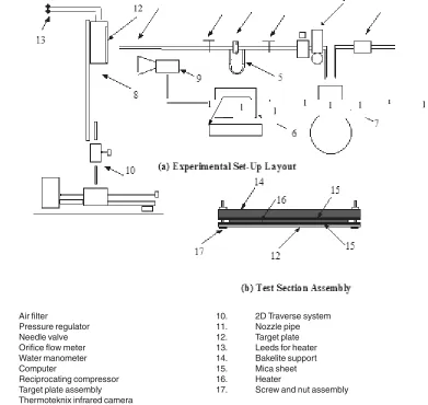
The experimental set up layout is depicted in Fig.1 (a). Air jet is supplied by a three-cylinder two-stage air compressor through a calibrated orifice flow meter. Air filter and Pressure regulator are installed upstream of the orifice flow meter to filter the air and to maintain the downstream pressure at a value of bar. The flow rate is controlled by two needle valves, one on each side of the orifice flow meter. The nozzle, which directs the air until it impinges upon a heated target plate, is constructed with a 7.35 mm inner diameter
aluminum pipe of length to diameter ratio of 83, which is almost same as that of Lyttle and Webb6. This length is sufficient to ensure fully developed flow over the Reynolds number range investigated. The end of the nozzle pipe is machined perpendicular to the nozzle axis. The impinging plate is constructed using 1mm thick stainless steel plate
of size . Nichrome heater of
size is packed between impinging
plate and a bakelite support plate with mica sheets in between to isolate the impinging plate from the heater electrically. To ensure that the impinging plate makes perfect contact with the heater, the impinging plate and bakelite support are tightened together with nuts and screws as shown in Fig.1 (b). This assembly is then insulated from all sides except
Fig. - 1: Experimental Test Set-Up
1. Air filter
2. Pressure regulator
3. Needle valve
4. Orifice flow meter
5. Water manometer
6. Computer
7. Reciprocating compressor
8. Target plate assembly
9. Thermoteknix infrared camera
10. 2D Traverse system
11. Nozzle pipe
12. Target plate
13. Leeds for heater
14. Bakelite support
15. Mica sheet
16. Heater
17. Screw and nut assembly
12
1 1 3 4 3 2
11 3 4 4 3 2 1 3 2 1 1 1 1 1 3 1
1 2
1
the impinging surface by ceramic wool and thermocole to reduce the back and side conduction losses. A two-dimensional traverse system is used to locate the target plate at a given position with respect to nozzle exit.
Electric power is supplied to the heater through variac. The voltage and the current are measured by digital panel meters. A K-type Chromel-Alumel thermocouple junction is soldered on the target plate at its extreme end to know about the steady state. The output of the thermocouple is measured by ‘Agronic’ milivoltmeter. Similarly,thermocouples are attached on cooled surface along the flow direction from the stagnation point with an interval of 5 mm between each ther mocouple to measure wall temperature distribution.
RESULTS AND DISCUSSION
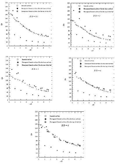
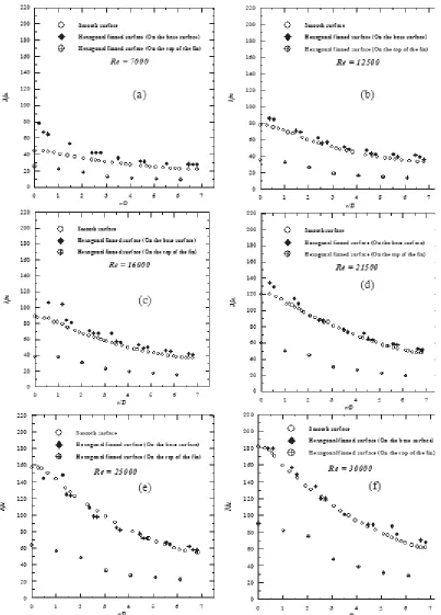
The heat transfer data is collected for five different nozzle plate spacing of 0.5, 1, 2, 4 and 6 times the diameter of the nozzle at a given Reynolds number of 23000 as shown in figure 2(a) to 2(e) and for six Reynolds numbers of 7000, 12500, 16000, 21500, 25000 and 30000 at given nozzle plate spacing of 6 times the nozzle diameter for smooth and finned surfaces as shown in figure 3(a) to 3(f). The heat transfer data for hexagonal finned surface shows an increase in Nusselt number as compared to smooth plate on the base surface and reduction in the Nusselt number on the top of the fins as compared to smooth surface. The total increase in the area of the hexagonal finned surface is about 41% as compared to the smooth surface. The increase in heat transfer is higher for Z/D of 1, and 2 as compared to other nozzle plate spacings. For Z/D of 1 the increase in the heat transfer on the base surface ranges between 24% to 49% depending on the radial location from the stagnation point and decrease in the heat transfer on the top of the fin at the stagnation point is about 50% as shown in fig.2(b).
Figure 3(a) to 3(f) shows the effect of Reynolds number on the heat transfer distribution at a nozzle – plate spacing of 6D and observed that there is increase in the heat transfer on hexagonal finned surface as compared to smooth surface.
Conclusions
An experimental evaluation is conducted in the present work to study the effect of the finned surface on the local heat transfer coefficients between the impinging circular jet and flat plate. The experimental parameters are the Reynolds number varied between 7000 and 30000 based on the nozzle exit condition and jet to plate spacing of 0.5, 1, 2, 4, 6 times the nozzle diameter. The configuration of surface in the form of fins studied, are hexagonal fins of side 2.04 mm and height of 2 mm spaced at a pitch of 7.5 mm on the target plate
The hexagonal finned surface increases the heat transfer coefficient from the target plate, of about 22 to 68 % at the base surface depending on the nozzle plate spacing and the Reynolds number in their ranges studied. The decrease in the Nusselt number at the top of the fin is about 41 to 70 %. The increase in the heat transfer for finned surface may be because of the increase in the swirl i.e. superposition of tangential velocity component onto the axial flow, which affects the turbulence characteristics of the flow and the decrease in the heat transfer coefficient at the top of the fins is because of the increase in the heat transfer area.
Nomenclature
D Diameter of the nozzle exit (m) h Heat transfer coefficient (W/m2.K) Nu Nusselt number (Dimensionless)
r Radial distance from the stagnation point (m)
Re Reynolds number based on nozzle exit condition (Dimensionless)
REFERENCES
1. R. Gardon and J. Cobonpue, Heat Transfer Between a Flat Plate and Jets of Air Impinging on It, Int. Developments in Heat Transfer, ASME 454-460 (1962) .
2. R Gardon and C.Akfirat, The Role of Turbulence in Determining the Heat Transfer Characteristics of Impinging Jets, Int. J. Heat and Mass Transfer, 8, 1261- 1272 (1965) . 3. R Gardon and C. Akfirat, Heat Transfer
Characteristics of Impinging Two Dimensional Air Jets”, J. of Heat Transfer, 88, 101-108. (1966).
4. J. W. Baughn and S. Shimizu, “ Heat Transfer Measurements From a Surface With Uniform Heat Flux and an Impinging Jet”, J. of Heat Transfer, 111, 1096-1098 (1989) .
5. P. Hr ycak, Heat Transfer from Round Impinging Jets to a Flat Plate, Int. J. Heat Mass Transfer, 26, 1857-1865 (1983). 6. D. Lytle, B. W. Webb, Air Jet Impingement
Heat Transfer at Low Nozzle Plate
Spacings, Int. J. Heat and Mass Transfer, 37, 1687-1697 (1994).
7. H. Martine, Heat and Mass Transfer between Impinging Gas Jets and Solid Surfaces, Adv. Heat Transfer, 13, 1-60 (1977).
8. K. Jambunathan, E. Lai, M. A. Moss, B.L. Button, A Review of Heat Transfer Data for Single Circular Jet Impingement, Int. J. Heat and Fluid Flow, 13, 106- 115 (1992). 9. R. Viskanta, Heat Transfer to Impinging
Isother mal Gas and Flame Jets, Experimental Thermal and Fluid Science, 6, 111-134 (1993).
10. L. G. Hansen, B. W. Webb, Air Jet
Impingement Heat Transfer from Modified Surfaces, Int. J. Heat Mass Transfer, 36 , 989-997 (1993).