R E S E A R C H A R T I C L E
Open Access
Design and testing of a 96-channel neural
interface module for the Networked
Neuroprosthesis system
Autumn J. Bullard
1, Samuel R. Nason
1, Zachary T. Irwin
1, Chrono S. Nu
1, Brian Smith
2, Alex Campean
2,
P. Hunter Peckham
2,3, Kevin L. Kilgore
2,3,4, Matthew S. Willsey
5, Parag G. Patil
1,5,6,7and Cynthia A. Chestek
1,8*Abstract
Background:The loss of motor functions resulting from spinal cord injury can have devastating implications on the quality of one’s life. Functional electrical stimulation has been used to help restore mobility, however, current functional electrical stimulation (FES) systems require residual movements to control stimulation patterns, which may be unintuitive and not useful for individuals with higher level cervical injuries. Brain machine interfaces (BMI) offer a promising approach for controlling such systems; however, they currently still require transcutaneous leads connecting indwelling electrodes to external recording devices. While several wireless BMI systems have been designed, high signal bandwidth requirements limit clinical translation. Case Western Reserve University has developed an implantable, modular FES system, the Networked Neuroprosthesis (NNP), to perform combinations of myoelectric recording and neural stimulation for controlling motor functions. However, currently the existing module capabilities are not sufficient for intracortical recordings.
Methods:Here we designed and tested a 1 × 4 cm, 96-channel neural recording module prototype to fit within
the specifications to mate with the NNP. The neural recording module extracts power between 0.3–1 kHz, instead of transmitting the raw, high bandwidth neural data to decrease power requirements.
Results:The module consumed 33.6 mW while sampling 96 channels at approximately 2 kSps. We also investigated
the relationship between average spiking band power and neural spike rate, which produced a maximum correlation of R = 0.8656 (Monkey N) and R = 0.8023 (Monkey W).
Conclusion:Our experimental results show that we can record and transmit 96 channels at 2ksps within the power
restrictions of the NNP system and successfully communicate over the NNP network. We believe this device can be used as an extension to the NNP to produce a clinically viable, fully implantable, intracortically-controlled FES system and advance the field of bioelectronic medicine.
Keywords:Brain machine interface, Functional electrical stimulation, Implantable, Neural interface, Low power
Background
According to the National Spinal Cord Injury Statistical Center, there are approximately 282,000 people living with chronic spinal cord injury (SCI), with 17,000 new cases occurring each year (National Spinal Cord Injury
Statistical Center 2016). Damage to the spinal cord can
disrupt the pathway of signals sent between the brain and the body and may result in partial or complete loss of both motor and sensory functions below the level of injury. The loss of these functions can have a major im-pact and severely interfere with activities of daily living related to arm and hand function, walking, bladder and bowel control, and trunk stability. Interestingly, restor-ation of arm and hand function was ranked as the high-est priority amongst individuals with tetraplegia and could significantly improve quality of life (Anderson
2004). Functional electrical stimulation (FES), a
* Correspondence:[email protected]
1
Department of Biomedical Engineering, University of Michigan, Ann Arbor, MI, USA
8Department of Electrical Engineering and Computer Science, University of
Michigan, Ann Arbor, MI, USA
Full list of author information is available at the end of the article
technique that uses pulses of electrical current to gener-ate contractions of muscles, has been beneficial in assist-ing and improvassist-ing the impaired motor function in individuals with SCI. FES has made great strides in
im-proving not only hand function (Peckham et al. 1980;
Alon and McBride2003; Popovic et al.2002; Kilgore et
al.2008), but also walking (Daly et al. 2011; Thrasher et
al. 2006), and controlling bladder functions (Gaunt and
Prochazka2006).
FES systems have been controlled by the user via physical switches, shoulder motion, and wrist position, which allows patients to cycle through pre-programmed
stimulation patterns (Prochazka et al.1997; Snoek et al.
2000; Handa et al.1992; Johnson et al.1999; Smith et al.
1987). These previous methods provided somewhat
coarse and binary control of the limb. Current FES sys-tems use residual myoelectric activity or joint angles as a method of control to achieve more finely tuned
move-ments (Memberg et al. 2014; Smith et al. 1987).
Although these current methods may work for individ-uals with partial paralysis, they can be unintuitive for pa-tients and only provide a few degrees of freedom. Further, in high cervical SCI, there is little or no residual motor function to provide an appropriate input stimulus to control such systems. Thus, a control solution which can provide more function to patients with all levels of injury is needed.
Brain machine interfaces (BMIs) have demonstrated great potential for generating control signals for
pros-thetic devices (Chapin et al. 1999; Collinger et al.2013;
Gilja et al. 2015; Hochberg et al. 2012; Velliste et al.
2008). The capability of BMIs to decode intended
move-ment directly from the brain can be used to control FES systems, potentially restoring natural function to pa-tients with all levels of spinal cord injury. Recently, groups have successfully used intracortically recorded signals from Utah microelectrode arrays (Blackrock Microsystems, Salt Lake City, UT) to predict movements or electromyogram (EMG) patterns to control FES
sys-tems (Ajiboye et al. 2012; Bouton et al. 2016; Ethier et
al.2012). Bouton et al. demonstrated that multiunit
ac-tivity in a paralyzed human could be used to control muscle activation directly and provide continuous con-trol of isolated finger movements and six different wrist
and hand postures (Bouton et al. 2016). Most recently,
Ajiboye et al. enabled a person with a C3 level injury to perform self-feeding activities using Utah
array-con-trolled FES (Ajiboye et al.2017). Although cortical
con-trol of FES is promising, current BMIs still require percutaneous leads connecting indwelling electrodes to external recording devices that can increase the risk of infection and limit portability. Therefore, wireless tech-nology is required to move towards a fully implantable and clinically viable device.
Many groups have designed and built custom
implant-able, wireless neural recording devices (Aziz et al. n.d.;
Gao et al. 2012; Moo Sung Chae et al. 2009; Park et al.
2018; Wattanapanitch and Sarpeshkar 2011). However,
none have been FDA approved or tested in humans. One of the major challenges in translating these systems into clinical use is the high bandwidth needed to access individual neural waveforms. The need to acquire, process, and transmit this broadband neural data dra-matically increases the power requirements of the de-vice, which results in large batteries with low battery life. For example, Borton et al. developed a 100 channel, her-metically sealed, implantable neural recording system. This device transmits broadband data at 24Mbps, re-quires 90.6 mW, and can last 7 h on a medical grade
200mAh battery (Borton et al. 2013). Similarly, Miranda
et al. developed a 32-channel system of primarily off the shelf components that delivered broadband data at 24
Mbps, using 142 mW (Miranda et al.2010). This system
can last up to 33 h but requires two 1200 mAh batteries. In all cases, the high power requirement prevents the use of compact batteries with adequate battery life prac-tical for an implantable device.
One method for saving power is to reduce the system bandwidth by focusing on relevant BMI features of the intracortical signals. Intracortical BMIs typically analyze
the action potential or“spike”frequencies. Spikes are
de-tected in the broadband signal by setting thresholds and counting the number of crossings in regular time inter-vals. These spike counts can be used to predict both continuous and discrete movements. Spike sorting indi-vidual neurons may be beneficial if an electrode is re-cording neurons with independent tuning patterns, otherwise, if electrodes primarily have only one neuron or similarly tuned neurons then a substantial perform-ance gain is not expected. Numerous studies have used thresholded spikes in BMI experiments and have shown that there is minimal or no performance loss when com-pared to sorted action potentials extracted from the
broadband data (Chestek et al. 2011; Fraser et al.2009).
In investigation of spike sorted data in comparison to thresholded data for the use in BMIs we have previously shown that spike sorting does not substantially improve decoding performance. Using a Naïve Bayes classifier with both thresholded and spike sorted data, we demon-strated percent accuracy only changed by an average of 5% and the correlation coefficient only differed by 0.015
(Christie et al. 2015). Thus, instead of transmitting the
entire broadband signal, only the spike counts are
needed to generate commands (Harrison et al. 2009).
This immensely compresses the data, decreasing the re-quired data rate for transmission. Beyond using spike counts, Stark and Abeles found that most of the decod-ing information received from spikes could also be
found in the signal frequency band of 300–6000 Hz, which includes the spike waveform frequencies (Stark
and Abeles 2007). We have previously shown this
band-width can be further reduced to 300–1000 Hz and
ex-tract similar intracortical information (Irwin et al.2016).
We refer to this 300–1000 Hz band as the “spiking
band”. Specifically, we developed a 16-channel wireless neural interface to assess the power savings and BMI de-coder performance of this approach. We compared the decode performance of continuous finger position using a Wiener filter between high bandwidth data using spike counts and low bandwidth data using the spiking band. That study showed that instead of transmitting the en-tire broadband signal, extracting only signal power within a narrow frequency band allowed for a reduced sampling rate and resulted in a power savings of roughly 90% with only a 5% performance loss of the accuracy of
the decoder (Irwin et al. 2016). This approach could be
applied in the context of existing fully implantable sys-tems to decrease power consumption and allow for prac-tical neural control of FES devices.
One efficient way to move the field towards a fully im-plantable intracortical BMI-FES system for clinical use may be to merge a neural recording device with an already existing fully implantable FES system. Using similar signal processing techniques from our previous
wireless device (Irwin et al. 2016), we developed a novel
96-channel intracortical recording device to be used as an extension to the modular, fully implantable FES system developed at Case Western Reserve University. In this paper we describe a feasibility study for power, perform-ance, and form factor to mate with their system and the prospect of an implantable cortical-controlled FES system.
Methods
Networked Neuroprosthesis system
The Networked Neuroprosthesis (NNP) is a system of implantable modules used to record residual EMG and perform many combinations of neural stimulation for controlling grasp and other motor functions (Smith et
al. 2005). While other implantable FES systems and
modular networks have been developed (Ghoreishizadeh et al. 2017; Guiraud et al. 2014; Jovičić et al. 2012), to our knowledge, the NNP is currently the only fully im-plantable FES system in initial human testing for hand function. It consists of a single central power module, and multiple actuator and sensor modules that are all in-terconnected via a network cable. The central power module is used for battery housing and wireless transfer. It manages power distribution and has the capability to monitor and program functions to other modules throughout the network. The actuator module is respon-sible for providing stimulation to muscles or nerves while the sensor module records biopotential data. The
network cable provides the power and high-speed data link for the modules with a two wire Controller Area
Network-like (CAN) bus protocol (Kilgore et al. 2007;
Smith et al.2005).
The current NNP sensor modules are designed with two bipolar channels to record EMG. These sensor modules are not equipped to support 96-channel intra-cortical neural recordings. However, the NNP system architecture was designed as a platform technology to accept new modules with added functionality. Theoretic-ally, a separate 96-channel neural recording module can be added to the NNP system to facilitate cortical con-trolled FES. This module would need to adhere to the guidelines of the standard NNP sensor modules: fit into the approved 1 cm × 3 cm hermetically sealed packaging of the sensor modules, include CAN capabilities, and meet the requirements of the 50 kbps network band-width and the target power consumption of about 30 mW. Because the NNP has been cleared for human test-ing and offers an open architecture, we chose this as our base system to test the feasibility of a fully implantable, cortically controlled FES system. The final system will record neural data from a 96-channel Utah array and gen-erate command signals for grasping using low power cir-cuitry and the spiking band feature extraction technique. Herein, we present the design and experimental results of this neural recording module prototype, including valid-ation using novel datasets with intracortical recordings from rhesus macaques performing finger movements.
Cortical controlled FES system overview
The envisioned intracortical FES system is shown in
Fig. 1. The existing NNP architecture is used for
muscle stimulation, power, and communication, while the novel intracortical recording module presented here generates control signals based on user intention. The novel recording module records data from a 96-channel Utah array in motor cortex, extracts the signal power in the 300–1000 Hz frequency band, and will ultimately predict the user’s motor intention using
decoding techniques similarly to (Irwin et al. 2016).
That intention is then converted into appropriate stimulation patterns by the power module and stimu-lates the paralyzed limb via the actuator module. The central power module of the NNP provides power to all sensor and actuator modules and provides a com-munication pathway both between modules and for ex-ternal programming.
interferance of the signal. The neural recording module will then be connected to other modules of the NNP throughout the body via the network cable.
Recording module hardware design
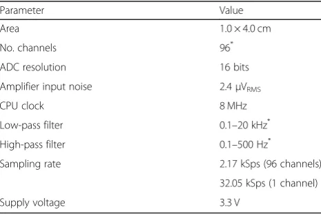
The initial design specifications for this module,
summa-rized in Table 1, were determined based on the existing
design of the Networked Neuroprosthesis from Case Western and from the design of our previous wireless
system (Irwin et al. 2016). The recording module is
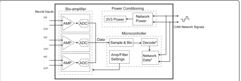
de-scribed by the block diagram in Fig. 2. It has a
96-channel front-end which filters and digitizes the in-coming neural data. The absolute value of the data on each channel is binned by the central microcontroller of the device by averaging over a given time interval to
calculate the mean signal power. Decoding and commu-nication over the CAN bus have not yet been imple-mented. However, in the future, the power on all channels will be decoded by the central microcontroller to predict the user’s intended grasp type. Finally, the decoded grasp type will be sent over the network to the NNP modules for appropriate muscle stimulation. Here, we validate the module’s ability to record the neural data at power levels that will work in conjunction with the entire system.
The module was implemented using entirely commer-cial, off-the-shelf components. The front-end consists of three Intan RHD2132 32-channel bioamplifiers that combine analog and digital filters and a multiplexed 16-bit ADC. The upper and lower bandwidths of the amplifiers and number of active channels can be easily configured by the central microcontroller (MCU) via a standard four-wire SPI interface. The MCU has three USART ports that are configured for SPI to transmit data from all three amplifiers simultaneously. The lower cutoff frequency of the amplifier bank is adjustable from 0.1–500 Hz, while the upper cutoff range is 100–20,000 Hz. The ADC sampling rate is controlled by the MCU, which was set to approximately 2 kSps per channel when using all 96 channels to measure signal power, or approximately 30 kSps for a single channel’s single unit recording. The power consumption of the amplifiers is proportional to the upper cut off frequency and scales at
7.6μA/kHz per channel. The chosen upper cut off
fre-quency is the major factor in the power consumption of the amplifiers. The upper cut off frequency also deter-mines the minimum sampling rate that can be applied,
Fig. 1Concept diagram for brain-controlled FES. The grey box denotes the existing NNP system and the red box denotes the planned novel module
Table 1Neural Recording Module Design Specifications
Parameter Value
Area 1.0 × 4.0 cm
No. channels 96*
ADC resolution 16 bits
Amplifier input noise 2.4μVRMS
CPU clock 8 MHz
Low-pass filter 0.1–20 kHz* High-pass filter 0.1–500 Hz*
Sampling rate 2.17 kSps (96 channels)
32.05 kSps (1 channel)
Supply voltage 3.3 V
*
Configurable in software
which is a major factor on the MCU processing and power consumption of the overall system.
A 32-bit Atmel ATUC3C2256C MCU serves as the central controller and data processor, configuring the front-end amplifiers, controlling the rate of data flow, as well as eventually communicating with existing NNP cir-cuitry via a CAN-like bus. Feature extraction from the data is performed on the MCU by averaging the absolute value of the data over a specified bin size that is pro-grammed, which we define as spiking band power. The MCU is clocked via an external crystal oscillator at 8 MHz which is internally divided for device operation and SPI communication. The MCU is programmed from an external computer via a ten-pin AVR JTAG interface, and system configuration settings can be easily modified in the application code.
The MCU’s Direct Memory Access (DMA) controller allows sampling of the bioamplifiers without processor oversight and was used to save power. The system is configured to initialize the 8 MHz clock, USART mod-ules, and Intan amplifiers using the fully active MCU at startup. After initialization, the DMA controller is then set up to sample data using the USART peripheral (in SPI mode) and transfer it to internal memory. Once it is enabled, the MCU enters a low-power sleep mode. Since the USART module has a lower bit resolution than the Intan amplifiers, a small amount of glue logic was re-quired to drive the MCU’s SPI interface to each ampli-fier while the MCU remained asleep. A D-flip flop, AND-gate, and necessary propagation delay circuitry were added to each chip select line on each SPI bus to drive the MCU’s SPI interface for compatibility with each amplifier while the MCU remained asleep.
The remaining circuitry is responsible for network communication and power conditioning. This section uses identical components and a similar layout as the existing modules of the NNP. The network is designed to be DC isolated and is used to communicate with
other NNP modules using the CAN bus protocol. The power conditioning circuitry will ultimately be respon-sible for harvesting power from the network.
Printed circuit board layout
NNP remote modules are designed to have several 1 cm wide rigid printed circuit board (PCB) panels, connected via flexible PCBs. This enables the modules to be folded to fit in a 1 cm wide enclosure, while maintaining com-ponent layout space. These modules can additionally ac-commodate variable length enclosures, and designers have the choice of trading off module length for circuit board density and complexity.
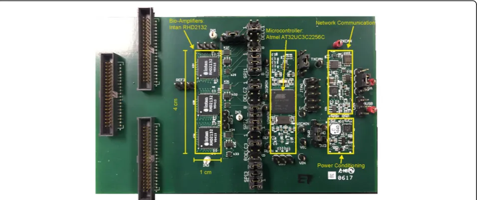
The novel module described thus far was prototyped on a six-layer printed circuit board. The prototype layout
is shown in Fig. 3. All active circuitry fit within three 1
cm × 4 cm panels in order to test the feasibility of fitting within an NNP package. Ultimately, a fourth panel will be used comprised of all bond pads to connect internal circuitry to the external electrode array. The limiting factor was the 32-channel Intan chips. All three Intan bioamplifiers were put on one panel with signal lines ex-tending out from the side of the board. This solution re-quired an extension of the board length from 3 cm for a typical NNP module to 4 cm for the novel module. A total of 12 signal lines pass between the bioamplifier and microcontroller panels, four SPI lines for each amplifier, all on one inner layer. In addition, only four lines pass between the microcontroller panel and the communica-tion and power panel. This will enable future versions to be fabricated with a rigid-flex circuit board that allows folding to fit within an NNP remote module enclosure
(illustrated in Fig.4). Most of the components outside of
these panels are only used to facilitate benchtop testing and are not required for device operation. This includes test points, programming headers, and Samtec connec-tors that can connect directly to a Utah array head stage (Blackrock Microsystems). The remaining glue logic
components were later added unconstrained to the out-lined panels to avoid any major design changes; however, they could fit with the necessary adjustments.
Experimental design and device validation
We explored the module’s ability to record in single channel (30 kSps) and multichannel (2 kSps) modalities. The sampling rate is approximate and can vary slightly based on code configurations. In each modality, the power consumption and its correlation to channel count was analyzed. In addition, we used the module to inves-tigate the relationship between spiking band power and the firing rate of action potentials. This neural recording module was validated using pre-recorded data that was played back through the module and in vivo intracortical recordings directly from a rhesus macaque. All animal procedures were approved by the University of Michigan
Institutional Review Board and the Institutional Animal Care & Use Committee.
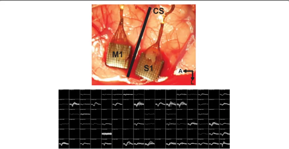
Surgical Implantation & Electrophysiology
Two rhesus macaque monkeys were induced under gen-eral anesthesia and placed in a stereotactic frame. The craniotomy site was located using the stereotactic frame to estimate the location of the central sulcus. The hand region of primary motor cortex (M1) was approximated by projecting a line from the genu of the arcuate sulcus posteriorly toward the gyrus immediately anterior to the central sulcus. The location of hand in the somatosen-sory cortex (S1) was approximated as the gyrus immedi-ately posterior to the central sulcus across from the motor hand region. Two 4 mm × 4 mm, 96-channel, intracortical Utah arrays (Blackrock Microsystems) were implanted in motor and sensory hand region as shown in Fig.5.
Fig. 3Prototype board used for testing. Three panels (left to right): bioamplifiers, microcontroller, network and power circuitry
Fig. 4(Left) Example mockup of final design with flexible circuitry. (Right) Demonstration of folded board to fit within the NNP module canister
Broadband data were recorded at 30 kSps from the ar-rays using a Cerebus Neural Signal Processor (Blackrock Microsystems). Neural spikes were detected by high-pass filtering the raw data at 250 Hz and thresholding the
resulting signal at −4.5 times the RMS voltage on each
channel, similar to other experiments (Gilja et al.2015).
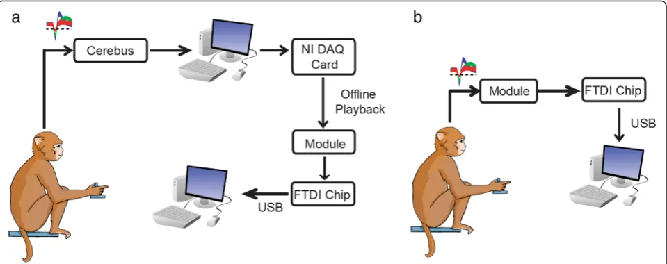
Experimental setup
Data playback Validation of the module in both sin-gle channel and multichannel modes were performed using pre-recorded data. Broadband data that had
been previously recorded through the Cerebus
(Blackrock Microsystems) and saved to an external computer were replayed through the module using a National Instruments DAQ card (PCI-6711) and then sent to a computer to view for further analyses,
shown in Fig. 6a. The DAQ was a 12-bit, 4 channel,
1 MS/s analog output device. This was used in con-junction with a shielded connector box (NI SCB-68A) to access the channels and connected to the module via Samtec connectors. The output of the DAQ was adjusted via a voltage divider in order to achieve the original signal amplitude and outputted at the original recorded sampling rate at 30 kHz.
Sending known pre-recorded data through the device allowed for verification that the output data was correct. Additionally, whereas the general spike waveform is
known and can be visually detected in the signal, the spiking band waveform is not and offline comparison with the exact same data is critical. In practice, the sys-tem will not need to send neural data off the device. A motor command will be decoded from the data and sent over the NNP system to be transformed into a stimula-tion pattern. However, for testing purposes, the recorded data was sent to a computer for analyses and validation of the module. In 2 kSps mode, at the end of each bin period, the module computes the average for each chan-nel. At the completion of either 2 kSps or raw 30 kSps data, the device passes all the recorded data to an exter-nal computer through USART, using an FTDI chip as a USB interface for analyses and validation. Neural action potentials are visible when in single channel mode and the spiking band power is visible in multichannel mode and are later compared to PC-processed data.
In vivo recordings Data was also recorded by the mod-ule in vivo directly from a monkey. During these record-ings, the monkey sat in a primate chair (Crist Instruments) with his head restrained not performing any task. A Cereport breakout connector was used to connect the array pedestal to the module through the Samtec connectors. Neural data was recorded directly through the device and sent to an external computer
using an FTDI chip as a USB interface, shown in Fig.6b.
Results
Device validation
Figure3shows the final device, 1 cm × 4 cm for each of 3
panels. Currently this prototype does not include the flex-ible connections between panels, but only 16 lines run be-tween the panels, such that the same layout could be fabricated in a flex design. An example of this flex design
is illustrated in Fig.4. This design was tested extensively
on the benchtop and with animals as described below.
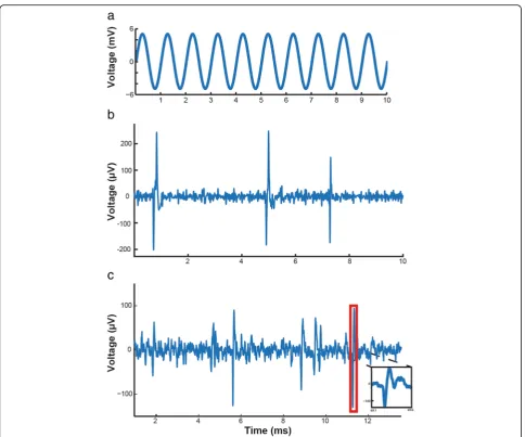
Pre-recorded data
First, we verified that signals were passing reliably through the Intan amplifiers to the microcontroller. During these tests, the module was powered by a DC regulated power supply at 3.3 V, bypassing the built-in power conditioning circuitry. The amplifiers were con-figured to filter a passband of 0.1–7500 Hz and were sampled at 32 kSps. These settings enabled testing of the wideband performance of the device. The sampled data was transmitted to an external computer for storage and processing. In single channel mode, signals were intro-duced and verified at individual inputs on each bioampli-fier. Individual channel investigation was necessary, as the system was designed to process data at much lower rates and the microcontroller cannot handle the throughput ne-cessary for all 96 channels at 32 kSps. However, the spik-ing band of all 96 channels can be processed in
multichannel mode at 2ksps. Figure7shows the results of
testing in single channel mode, where details of the in-coming signal can be easily viewed. First, a 1 kHz sine wave was introduced to the amplifier input and the
sam-pled output at 32 kSps, shown in Fig.7a. The device was
next validated with simulated neural signals from a neural
signal generator (Blackrock Microsystems). Figure 7b
shows an example recording where spikes were clearly
vis-ible. Figure 7c shows an example using real,
prere-corded neural data at 32 kSps from a rhesus macaque performing finger flexion tasks. All channels looked and performed similarly.
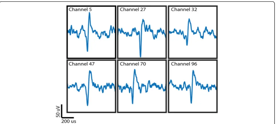
In vivo data
For consideration as a future clinical system, the device also needs to be able to handle the noise and imped-ances associated with live recordings. We tested this by recording directly from a Utah array in a nonhuman
pri-mate. Figure 8 shows an example recording from six
channels showing clear single unit activity, manually picked out. Data recorded through the device had an
RMS noise of 3.2μVRMS which is comparable to that of
the Cerebus at 2.1 μVRMS. These channels were
re-corded separately, as this device is not designed to process 30 kSps data on all 96 channels, as the MCU cannot sample that fast and it would consume too much power for the overall system. However, these results show it is possible to record one channel of broadband data for basic science purposes, or for calibration pur-poses in a clinical system.
Spiking band power validation Module outputs spiking band power
Next, we tested the intended usage mode where all 96 channels are recorded at once, using a spiking band filter similar to that used by Stark and Abeles (Stark and
Abeles2007). The device was configured to filter inputs
between 300 and 1000 Hz, which we previously showed to enable decoding with 95% of the performance associ-ated with decoding threshold crossing events (Irwin et
al. 2016). The microcontroller sampled all 96 channels
Fig. 6Experimental Setup.aWhile the monkey performs the finger flexion task, broadband neural data is recorded through the Cerebus and saved on a computer. The offline data is later replayed through the module using a National Instruments DAQ card.bWhile the monkey sits still, neural data is recorded through the device and sent to a computer
at 2.17 kSps and transmitted the averaged absolute value of the signal after 128 samples (~ 58 ms bins) to a com-puter for analysis. This mode was tested with raw pre-recorded neural data from Utah arrays, played back through the device, such that it could be compared in multiple ways. We performed the same processes used on the device offline in Matlab. The same broadband dataset used to playback through the device was filtered between 300 and 1000 Hz with a 2nd order Butterworth filter, downsampled to 2 kSps, and the absolute value was averaged over 58 ms to estimate the mean signal
power on each channel. The output from the
pre-recorded data played back through the device was compared to the offline processed result. The offline
Matlab results and the device output are shown in Fig.9,
where the two signals matched closely, with a Pearson’s correlation coefficient of 0.9607.
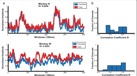
Comparing spiking band to spiking rate
In Irwin et al, we showed that low bandwidth intracorti-cal data could be used to predict a monkey’s continuous finger position. In comparison to decodes using spike counts acquired from high bandwidth data, performance
drops by only 4.9% (Irwin et al. 2016). One explanation
of this is that signal power within 300–1000 Hz repre-sents the firing rate of neurons on a particular channel, leading to a similar decode performance. To further test whether the spiking band power results from actual spikes, we compared the spiking band power output from the device to the firing rate obtained from thresh-olding the broadband data, as used in many online BMI experiments. Datasets were chosen for the two monkeys (N, W) on days with similar tasks and performance. Within these datasets, the channels with visualized sin-gle unit waveforms were used in the analyses. Using
Matlab, the mean firing rate was calculated in 100 ms windows. The same broadband datasets were replayed through our device, which returned the 2 kSps spiking band power, which was then averaged offline in Matlab with the same 100 ms window size. We compared the traces of mean firing rate and mean power over multiple channels and used the correlation coefficient to assess their agreement. This yielded a mean correlation of R = 0.8656 in Monkey N and R = 0.8023 in Monkey W. The high correlation between firing rate and signal power suggests that the spiking band is related to actual spiking events and is not only capturing local field potentials (LFP). The channel with the best performance in each
monkey is shown in Fig.10a. Histograms of per-channel
correlations are shown in Fig.10b. The varying
distribu-tion of correladistribu-tion across the channels and different
animals can be attributed to the variance of the ampli-tude and activity frequency of the neurons during the defined time window.
Power consumption
In each mode, power was calculated by measuring the total system current through a jumper. Most of the power was consumed by the three Intan RHD2132s and the Atmel AT32UC3C2256C microcontroller. With all power saving techniques in use, system power was measured at 33.6 mW while sampling 96 channels at 2 kSps, config-ured to filter between 300 and 1000 Hz. As a comparison, the power required to transmit a single channel, filtered between 0.1–7500 Hz at 30 kSps, using our system was 31.2 mW. To transmit a single channel at 2 kSps, only 22.1 mW were needed. The primary single-channel power
Fig. 8Single units recorded in vivo through the device. Each channel was recorded individually
Fig. 9Power calculated from 2 kSps data offline compared to data output from the device on a single channel
savings came from the reduced filter bandwidth and sam-pling rate. While it would not be practical to stream 96 channels at 30 kSps, it is possible to view single unit wave-forms one at a time using this approach.
To achieve this lower power consumption and ease the burden on the overall system power management of the NNP, we used several features of the MCU to de-crease overall power consumption, summarized in
Table 2. First, we enabled the DMA which allowed the
device to control sampling from the amplifiers without having to wake up the processor from a low-power sleep mode. The DMA was more efficient at sampling and was necessary to acquire data from all 96 channels at 2 kSps. The core alone could manage a maximum of 1 kHz while at the full clock rate, while the DMA could still exceed the sampling rate even after a major reduc-tion in clock speed. System power was measured at 45.3 mW while transmitting all 96 channels at 2 kSps using
the DMA. Next, we disabled all unused peripherals on the MCU. Using the DMA and turning off unused peripherals decreased power consumption by 11% to 40.0 mW. Finally, the processor core was configured to spend most of its time in IDLE sleep mode. Since the DMA automates sampling, the MCU core only needs to wake up every 64 ms to bin the data. With all these power saving techniques enabled, system power was measured at 33.6 mW, a 16% reduction from when the CPU is fully awake, and a 25% reduction overall.
In addition to the techniques discussed above, redu-cing the number of channels transmitted could also re-duce the amount of power consumed by the device. Selectively using only the well-tuned channels has been shown to positively contribute to the decode
perform-ance (Wahnoun et al. 2006). This concept of channel
masking allows us to record from only a subset of chan-nels and retain the decode performance. We simulated
Fig. 10aComparison of mean spiking band power from the device normalized to the maximum power and firing rate calculated offline normalized to the maximum firing rate over 100 ms windows for the best single channel.bHistograms of the correlation coefficients for all channels in the dataset
Table 2Power Saving Techniques
No. Channels Power Mode System Power
1 30ksps 31.2 mW
1 2ksps 22.1 mW
96 2ksps DMA sampling + CPU awake 45.3 mW
96 2ksps DMA sampling + Disabled Peripherals + CPU awake 40.0 mW
this by recording from only a portion of the channels evenly distributed across all three amplifiers. Transmit-ting all 96 channels in the lowest power mode required 33.6 mW. Disabling roughly a third of the channels to transmit only 63 channels consumed 31.4 mW. Disabling approximately two thirds of the channels allowed a 50% reduction to the system clock speed, where transmitting 33 channels of data required 26.7 mW.
Additionally, for completeness, we tested functionality of the device’s CAN network interface and power condi-tioning circuitry by connecting it exclusively to an NNP power module and validated that the devices could com-municate. System power of the neural recording module was measured at 43.6 mA, while being powered by the NNP power module at 3.98 V, and recording and bin-ning all 96 channels, using the DMA as described above.
Discussion
We have designed a 96-channel neural recording mod-ule prototype that can be used with the NNP system. The neural recording module was designed using en-tirely off-the-shelf components and all active circuitry fit within 1 cm × 4 cm panels. While the current NNP ssor modules have a 1 cm × 3 cm hermetically sealed en-closure, increasing the length by 1 cm is not outside of the capabilities of the manufacturer and does not com-promise the design. Our device extracts signal power in a narrow frequency band, which allows us to sample at a low rate of 2 kSps. We demonstrated the neural record-ing module consumed 33.6 mW when transmittrecord-ing all 96 channels at 2 kSps using all power saving techniques. We have not yet implemented decoding and full com-munication over the CAN network and expect these functions to draw some additional power. However, we have tested the functionality of the CAN network while the device was being powered exclusively by the NNP power module and found our device’s power consump-tion to be similar to that of existing NNP permitting normal function of other modules (power, actuator, and sensor). Most demonstrations of wireless neural record-ing devices have been done usrecord-ing > 50 Mbps of digitized voltage traces, which is far beyond the specifications of implantable devices. The ability to sample at a lower rate tremendously decreases the size of the data and will be key in communication with the NNP network, which has a bandwidth of 100 kbps. Our current design uses three 8 mm × 8 mm 32-channel Intan bioamplifiers, which is a limiting factor in PCB length and power con-sumption of the module. However, the BGA packaging of the next generation 9 mm × 7 mm 64-channel Intan bioamplifier offers the possibility of improving our current design by decreasing the number of chips from 3 to 2. This will dramatically reduce the size of our board without any major design changes, bringing us
closer to the 1 cm × 3 cm package of the existing NNP modules. Each individual bioamplifier consumes some baseline power, so the reduction in the number of Intan bioamplifiers required will eliminate a portion of this power consumed and enable significant power savings. In addition, if the design option were available to reduce the 3.3 V supply voltage required for the Intan bioampli-fiers, that would lead to further reduction of the overall power consumption of the device.
Additionally, channel masking provides opportunities to save even more power. Wahnoun et al. found that less than 70% of recorded neurons are well tuned to move-ment direction and that some of these neurons actually decrease decoding performance. Selecting the best 20 neu-rons to control their neuroprosthetic system performed
better than using all neurons (Wahnoun et al. 2006).
Reducing the number of channels transmitted will reduce the computational load and result in a decrease in overall power consumption and prolonged battery life.
While it enables dramatic power savings, there are still
open questions about exactly where the “spiking-band”
signal is coming from. This is important in order to understand how far the approach can go. Is it a local sig-nal directly reflective of spikes? Or is it broader LFP like electrocorticography (ECoG), which can also contain
some movement information (Chestek et al. 2011; Flint
et al. 2016)? We have previously demonstrated that we
can drop the upper frequency of the spiking band filter
from 6 kHz (Stark and Abeles 2007) to 1 kHz with only
a 4.9% decrease in performance (Irwin et al.2016). Here,
we have shown that the power in the spiking band is highly correlated with the firing rate of threshold cross-ing spikcross-ing rate of the input high bandwidth data. This suggests that spiking band power may be most reflective of the spikes themselves. This is not surprising since ac-tion potentials have a 1–1.5 ms sinusoidal-like waveform, and we filtered between 300 and 1000 Hz. Spike ampli-tude also falls off quickly, theoretically as the reciprocal
of the distance from the electrode (Holt and Koch1999;
Moffitt and McIntyre2005), which makes it possible that
the spiking band signal is fairly local. Based on the fre-quency components it is likely that the spiking band contains both localized spikes and broader LFP. This may be a benefit to the traditional use of thresholded spikes because the spiking band may be used to still in-terpret useful data from channels that over time no lon-ger have good quality spikes.
Custom ASIC designs have been presented to be smaller in size and consume less power, however, the noise, impedance, and large transient voltages that are present in live data within real world settings make it difficult to also achieve signal integrity and stability under these conditions. With academic bioamplifiers progressing to a more commercial platform, we can
record live stable signals under very realistic parameters using off the shelf components, as seen with this device. Overall, using the signal processing techniques described here, custom ASIC-free designs may have crossed the threshold of viability for multi-channel neural recording.
At the moment, percutaneous wires and power are ar-guably the most limiting factors in translating BMI sys-tems to clinical use. The best devices run for only a few hours on a battery or rely on wearable components
(Borton et al.2013). So long as this is true, spiking band
devices may offer the fastest path to clinical viability. In the future, should the number of electrodes become more of a limitation than the power, it may make more sense to extract the maximum amount of information from each electrode by extracting single unit timing. Currently, however, several hundred electrodes can be
implanted percutaneously in humans (Aflalo et al.2015;
Collinger et al. 2013; Gilja et al. 2015; Hochberg et al.
2012), without being able to process even 100 of those
channels with implantable electronics.
Conclusion
This device was designed to acquire data at configur-able bandwidths, sampling rates, and channel counts using the Intan bioamplifiers which could allow it to be used for applications outside of Utah array record-ing. The freedom to choose the filter parameters sup-ports a variety of neural signal modalities, such as ECoG and EMG. While there are many interesting im-plantable devices in development for EMG (Baker et
al. 2010; Troyk et al. 2007) as well as wireless ECoG
for epilepsy (Mestais et al. 2015; Vansteensel et al.
2010), these devices would serve relatively small
mar-kets by themselves. However, the concept behind the NNP is that existing modules can be applied to mul-tiple applications and markets, as the stimulation and power modules can be used for a brain-controlled FES device theoretically proposed in this work. The specifi-cations in this paper, representing the first attempt to combine designs from different groups, can be used as a guide to develop further application specific mod-ules. While representing a departure from traditional medical devices, the reuse of components and circuitry from the existing NNP platform may dramatically ac-celerate the overall process to a clinically viable system within the scope of bioelectronic medicine.
Abbreviations
ADC:Analog to digital converter; BMI: Brain machine interface;
CAN: Controller area network; DAQ: Data acquisition; DMA: Direct memory access; ECoG: Electrocorticography; EMG: Electromyography; FES: Functional electrical stimulation; MCU: Microcontroller; NNP: Networked Neural Prosthesis; PCB: Printed circuit board layout; RMS: Root mean square; SCI: Spinal cord injury; SPI: Serial peripheral interface
Acknowledgements
The authors thank Joris Lambrecht for his assistance in testing the power and communication network circuitry of the neural recording module with the power module of the NNP system.
Funding
This research was supported by the Craig H. Neilsen Foundation, the National Science Foundation Graduate Research Fellowship, and the National Institute of Health T32 NS007222.
Availability of data and materials
Data generated or analyzed during this study are available from the corresponding author on reasonable request.
Authors’contributions
Contributed schematics and essential information from the NNP design- BS, AC, PP, KK. Performed surgeries- MW, PP. Conducted monkey experiments and collected data- AB, SN, CN. Designed, tested and validated the module-AB, SN, ZI. Drafted manuscript- AB. Reviewed and approved final version- module-AB, SN, ZI, CN, BS, AC, KK, PP, MW, PP, CC.
Ethics approval and consent to participate
All animal procedures were approved by the University of Michigan Institutional Animal Care and Use Committee (IACUC).
Consent for publication
Not Applicable.
Competing interests
The authors declare that they have no competing interests.
Publisher’s Note
Springer Nature remains neutral with regard to jurisdictional claims in published maps and institutional affiliations.
Author details
1
Department of Biomedical Engineering, University of Michigan, Ann Arbor, MI, USA.2Department of Biomedical Engineering, Case Western Reserve
University, Cleveland, OH, USA.3Department of Orthopaedics, MetroHealth Medical Center, Cleveland, OH, USA.4Research Service, Louis Stokes
Cleveland Department of Veterans Affairs Medical Center, Cleveland, OH, USA.5Department of Neurosurgery, University of Michigan, Ann Arbor, MI,
USA.6Department of Neurology, University of Michigan, Ann Arbor, MI, USA.
7Department of Anesthesiology, University of Michigan, Ann Arbor, MI, USA. 8
Department of Electrical Engineering and Computer Science, University of Michigan, Ann Arbor, MI, USA.
Received: 15 November 2018 Accepted: 25 January 2019
References
Aflalo T, et al. Decoding motor imagery from the posterior parietal cortex of a Tetraplecig human. Science. 2015;348(6237):906–10.https://doi.org/10.7910/ DVN/GJDUTV.
Ajiboye AB, et al. Prediction of imagined single-joint movements in a person with high-level tetraplegia. IEEE Trans Biomed Eng. 2012;59(10):2755–65. Ajiboye AB, et al. Restoration of Reaching and Grasping Movements through
Brain-Controlled Muscle Stimulation in a Person with Tetraplegia: A Proof-of-Concept Demonstration. Lancet. 2017;389(10081):1821–30http://www.ncbi. nlm.nih.gov/pubmed/28363483. Accessed 7 Oct 2018.
Alon G, McBride K. Persons with C5 or C6 Tetraplegia Achieve Selected Functional Gains Using a Neuroprosthesis. Arch Phys Med Rehabil. 2003;84(1): 119–24http://linkinghub.elsevier.com/retrieve/pii/S0003999302048918. Accessed 28 Mar 2017.
Anderson KD. Targeting recovery: priorities of the spinal cord-injured population. J Neurotrauma. 2004;21(10):1371–83.
Baker JJ, et al. Continuous detection and decoding of dexterous finger flexions with implantable myoelectric sensors. IEEE Trans Neural Syst Rehabil Eng. 2010;18(4):424–32.
Borton DA, Yin M, Aceros J, Nurmikko A. An implantable wireless neural Interface for recording cortical circuit dynamics in moving primates. J Neural Eng. 2013;10(2):1–25.
Bouton CE, et al. Restoring Cortical Control of Functional Movement in a Human with Quadriplegia. Nature. 2016;533(7602):247–50http://www.ncbi.nlm.nih. gov/pubmed/27074513. Accessed 7 Oct 2018.
Chae MS, et al. A 128-Channel 6 MW Wireless Neural Recording IC With Spike Feature Extraction and UWB Transmitter. IEEE Trans Neural Syst Rehabil Eng. 2009;17(4):312–21http://ieeexplore.ieee.org/document/4912399/. Accessed 31 Oct 2018.
Chapin JK, Moxon KA, Markowitz RS, Nicolelis MA. Real-time control of a robot arm using simultaneously recorded neurons in the motor cortex. Nat Neurosci. 1999;2(7):664–70.
Chestek CA, et al. Long-term stability of neural prosthetic control signals from silicon cortical arrays in rhesus macaque motor cortex. J Neural Eng. 2011; 8(4):45005.
Christie BP, et al. Comparison of Spike Sorting and Thresholding of Voltage Waveforms for Intracortical Brain-Machine Interface Performance. J. Neural Eng. 2015;12:10http://iopscience.iop.org/1741-2552/12/1/016009. Accessed 19 Dec 2018.
Collinger JL, et al. High-Performance Neuroprosthetic Control by an Individual with Tetraplegia. Lancet. 2013;381(9866):557–64http://linkinghub.elsevier. com/retrieve/pii/S0140673612618169. Accessed 7 Oct 2018.
Daly JJ, et al. Recovery of coordinated gait: randomized controlled stroke trial of functional electrical stimulation (FES) versus no FES, with weight-supported treadmill and over-ground training. Neurorehabil Neural Repair. 2011;25(7):588–96. Ethier C, Oby ER, Bauman MJ, Miller LE. Restoration of Grasp Following Paralysis
through Brain-Controlled Stimulation of Muscles. Nature. 2012;485:368–71. Flint RD, et al. Long-term stability of motor cortical activity: implications for brain
machine interfaces and optimal feedback control. J Neurosci. 2016;36(12):3623–32. Fraser GW, Chase SM, Whitford A, Schwartz AB. Control of a Brain–computer
Interface without Spike Sorting. J Neural Eng. 2009;6(5):055004http://stacks. iop.org/1741-2552/6/i=5/a=055004?key=crossref.
51caa3a82917378613dbceba24cd05b7. Accessed 28 Mar 2017.
Gao H, et al. HermesE: A 96-Channel Full Data Rate Direct Neural Interface in 0.13 $\mu$m CMOS. IEEE J Solid State Circuits. 2012;47(4):1043–55http:// ieeexplore.ieee.org/document/6158616/Accessed 31 Oct 2018. Gaunt RA, Prochazka A. Control of urinary bladder function with devices:
successes and failures. Prog Brain Res. 2006;152:163–94.
Ghoreishizadeh SS, et al. Four-Wire Interface ASIC for a Multi-Implant Link. IEEE Trans Circuits Syst I Regular Pap. 2017;64(12):3056–67https://ieeexplore.ieee. org/document/8010903/. Accessed 31 Oct 2018.
Gilja V, et al. Clinical translation of a high-performance neural prosthesis. Nat Med. 2015;21(10):1142–5http://www.ncbi.nlm.nih.gov/pubmed/26413781. Guiraud D, Coste CA, Benoussaad M, Fattal C. Implanted Functional Electrical
Stimulation: Case Report of a Paraplegic Patient with Complete SCI after 9 Years. J Neuroeng Rehabil. 2014;11(1):15http://jneuroengrehab.
biomedcentral.com/articles/10.1186/1743-0003-11-15. Accessed 1 Dec 2017. Handa Y, et al. Functional electrical stimulation (FES) Systems for Restoration of
motor function of paralyzed muscles--versatile systems and a portable system. Front Med Biol Eng. 1992;4(4):241–55.
Harrison RR, et al. Wireless neural recording with single low-power integrated circuit. IEEE Trans Neural Syst Rehabil Eng. 2009;17(4):322–9.
Hochberg LR, et al. Reach and Grasp by People with Tetraplegia Using a Neurally Controlled Robotic Arm. Nature. 2012;485(7398):372–5http://www.nature. com/doifinder/10.1038/nature11076. Accessed 7 Oct 2018.
Holt GR, Koch C. Electrical interactions via the extracellular potential near cell bodies. J Comput Neurosci. 1999;6(2):169–84.
Irwin ZT, et al. Enabling low-power, multi-modal neural interfaces through a common, low-bandwidth feature space. IEEE Trans Neural Syst Rehabil Eng. 2016;24(5):521–31http://ieeexplore.ieee.org/document/7332964/. Johnson MW, et al. Implantable transducer for two-degree of freedom joint
angle sensing. IEEE Trans Rehabil Eng. 1999;7(3):349–59.
JovičićNS, Saranovac LV, PopovićDB. Wireless Distributed Functional Electrical Stimulation System. J Neuroeng Rehabil. 2012;9:54http://www.ncbi.nlm.nih. gov/pubmed/22876934. Accessed 31 Oct 2018.
Kilgore KL, Peckham PH, Crish TJ, Smith B. United States Patent. 2007;1(12):0–3.
Kilgore KL, et al. An Implanted Upper-Extremity Neuroprosthesis Using Myoelectric Control. J Hand Surg. 2008;33(4):539–50http://www.sciencedirect.com/science/ article/pii/S0363502308000117. Accessed 28 Mar 2017.
Memberg WD, et al. Implanted Neuroprosthesis for Restoring Arm and Hand Function in People With High Level Tetraplegia. Arch Phys Med Rehabil. 2014;95(6):1201–1211.e1http://www.sciencedirect.com/science/article/pii/ S0003999314001221. Accessed 28 Mar 2017.
Mestais CS, et al. WIMAGINE: wireless 64-channel ECoG recording implant for long term clinical applications. IEEE Trans Neural Syst Rehabil Eng. 2015;23(1):10–21. Miranda H, et al. HermesD: a high-rate long-range wireless transmission system
for simultaneous multichannel neural recording applications. IEEE Trans Biomed Circuits Syst. 2010;4(3):181–91.
Moffitt MA, McIntyre CC. Model-Based Analysis of Cortical Recording with Silicon Microelectrodes. Clin Neurophysiol. 2005;116(9):2240–50http:// www.sciencedirect.com/science/article/pii/S1388245705002257. Accessed 28 Mar 2017.
National Spinal Cord Injury Statistical Center. Facts and Figures at a Glance. Birmingham: University of Alabama at Birmingham; 2016.https://www.nscisc. uab.edu/Public/Facts%202016.pdf.
Park, SY, Cho J, Na K, and Yoon E. 2018.“Modular 128-Channel $\Delta$ - $\Delta \Sigma$ Analog Front-End Architecture Using Spectrum Equalization Scheme for 1024-Channel 3-D Neural Recording Microsystems.”Undefined.
https://www.semanticscholar.org/paper/Modular-128-Channel-%24%5CDelta%24-%24%5CDelta-%5CSigma%24-Analog-Park-Cho/ c5fcc3b581361b6ef896f32a6e739f9fe429dde2. Accessed 31 Oct 2018. Peckham PH, Mortimer JT, Marsolais EB. Controlled Prehension and release in the
C5 quadriplegic elicited by functional electrical stimulation of the paralyzed forearm musculature. Ann Biomed Eng. 1980;8(4–6):369–88.
Popovic MR, Popovic DB, Keller T. Neuroprostheses for grasping. Neurol Res. 2002;24(5):443–52http://www.ncbi.nlm.nih.gov/pubmed/12117312. Prochazka A, Gauthier M, Wieler M, Kenwell Z. The bionic glove: an electrical
stimulator garment that provides controlled grasp and hand opening in quadriplegia. Arch Phys Med Rehabil. 1997;78(6):608–14.
Smith B, Peckham PH, Keith MW, Roscoe DD. An externally powered, multichannel, implantable stimulator for versatile control of paralyzed muscle. IEEE Trans Biomed Eng. 1987;34(7):499–508.
Smith B, et al. Development of an Implantable Networked Neuroprosthesis. 2nd Int IEEE EMBS Conf Neural Eng. 2005, 2005:454–7.
Snoek GJ, et al. Use of the NESS Handmaster to restore Handfunction in tetraplegia: clinical experiences in ten patients. Spinal Cord. 2000;38(4):244–9. Stark E, Abeles M. Predicting movement from multiunit activity. J Neurosci. 2007;
27(31):8387–94.
Thrasher TA, Flett HM, Popovic MR. Gait training regimen for incomplete spinal cord injury using functional electrical stimulation. Spinal Cord. 2006;44(6): 357–61.
Troyk PR, DeMichele GA, Kerns DA, Weir RF. IMES: An implantable myoelectric sensor. In Annual International Conference of the IEEE Engineering in Medicine and Biology - Proceedings (pp. 1730–1733). 2007.https://doi.org/ 10.1109/IEMBS.2007.4352644
Vansteensel MJ, et al. Brain-computer interfacing based on cognitive control. Ann Neurol. 2010;67(6):809–16.
Velliste M, et al. Cortical control of a prosthetic arm for self-feeding. Nature. 2008; 453(7198):1098–101.
Wahnoun R, He J, Helms Tillery SI. Selection and parameterization of cortical neurons for Neuroprosthetic control. J Neural Eng. 2006;3(2):162–71. Wattanapanitch W, Sarpeshkar R. A Low-Power 32-Channel Digitally
Programmable Neural Recording Integrated Circuit. IEEE Trans Biomed Circuits Syst. 2011;5(6):592–602http://ieeexplore.ieee.org/document/ 6012491/. Accessed 31 Oct 2018.