Development of stereo endoscope
system with its innovative master interface
for continuous surgical operation
Myungjoon Kim
1, Chiwon Lee
2, Nhayoung Hong
1, Yoon Jae Kim
1and Sungwan Kim
3,4*Abstract
Background: Although robotic laparoscopic surgery has various benefits when compared with conventional open surgery and minimally invasive surgery, it also has issues to overcome and one of the issues is the discontinuous surgical flow that occurs whenever control is swapped between the endoscope system and the operating robot arm system. This can lead to problems such as collision between surgical instruments, injury to patients, and increased operation time. To achieve continuous surgical opera-tion, a wireless controllable stereo endoscope system is proposed which enables the simultaneous control of the operating robot arm system and the endoscope system. Methods: The proposed system consists of two improved novel master interfaces (iNMIs), a four-degrees of freedom (4-DOFs) endoscope control system (ECS), and a simple three-dimensional (3D) endoscope. In order to simultaneously control the pro-posed system and patient side manipulators of da Vinci research kit (dVRK), the iNMIs are installed to the master tool manipulators of dVRK system. The 4-DOFs ECS consists of four servo motors and employs a two-parallel link structure to provide translational and fulcrum point motion to the simple 3D endoscope. The images acquired by the endoscope undergo stereo calibration and rectification to provide a clear 3D vision to the surgeon as available in clinically used da Vinci surgical robot systems. Tests designed to verify the accuracy, data transfer time, and power consumption of the iNMIs were performed. The workspace was calculated to estimate clinical applicability and a modified peg transfer task was conducted with three novice volunteers.
Results: The iNMIs operated for 317 min and moved in accordance with the surgeon’s desire with a mean latency of 5 ms. The workspace was calculated to be 20378.3 cm3, which exceeds the reference workspace of 549.5 cm3. The novice volunteers were able to successfully execute the modified peg transfer task designed to evaluate the proposed system’s overall performance.
Conclusions: The experimental results verify that the proposed 3D endoscope system enables continuous surgical flow. The workspace is suitable for the performance of numerous types of surgeries. Therefore, the proposed system is expected to provide much higher safety and efficacy for current surgical robot systems.
Keywords: Three-dimensional (3D) endoscope system, Minimally invasive surgery (MIS), Improved novel master interface (iNMI), da Vinci research kit (dVRK), Hands-on-throttle-and-stick (HOTAS)
Open Access
© The Author(s) 2017. This article is distributed under the terms of the Creative Commons Attribution 4.0 International License (http://creativecommons.org/licenses/by/4.0/), which permits unrestricted use, distribution, and reproduction in any medium, provided you give appropriate credit to the original author(s) and the source, provide a link to the Creative Commons license, and indicate if changes were made. The Creative Commons Public Domain Dedication waiver ( http://creativecommons.org/publicdo-main/zero/1.0/) applies to the data made available in this article, unless otherwise stated.
RESEARCH
*Correspondence: [email protected]
4 Department of Biomedical
Engineering, Seoul National University College of Medicine, Seoul 03080, South Korea
come the limits of both kinds of surgeries and provide various benefits [6–10].
The da Vinci surgical robot (Intuitive Surgical Inc., Sunnyvale, CA, USA), which is the most cutting-edge and predominant surgical robot, has been used in more than three million MIS operations worldwide since 2000 [11]. Nevertheless, several issues still remain to be resolved. Among these issues is the discontinuous surgical flow that occurs whenever control is switched between the endoscope system and the patient side manipulator (PSM), which also exists in various surgical robot systems including the da Vinci surgical robot system. In this scenario, the surgeon has to abandon the control of the PSM by using a clutch button or pedal in order to control the endoscope sys-tem to change his/her view. The same control technique is required to regain control of the PSM [12]. This maneuver can lead to problems such as collision between surgical instruments, injury to patients (from surgical instruments being out of sight), increased operation time, and having to endure an unsatisfactory view to avoid swapping control [13]. Various approaches that attempt to solve this discontinuity issue proposed new master interfaces to control the endoscope system in parallel with the PSM. For exam-ple, a novel human–machine interface that tracks the surgeon’s facial motion via his/her iris and a tracker placed on his/her forehead has been proposed to control the position of the laparoscope [14]. A command interface for a combination of mouth gesture and voice command has also been proposed to control 3-DOF robotic endoscope systems [12]. An eye tracking endoscope control method has also been presented [15, 16] and a voice controlled robotic endoscope holder was developed [16]. Further, an interface that utilizes a pressure sensor sheet to track foot movement has been used to control surgical robot tools [17].
However, although the proposed interfaces allow simultaneous control of the endo-scope system and the PSM, they also have limitations: (i) they cannot be adapted to current robot-assisted surgical systems as the surgeon’s head and foot are already occu-pied [14, 17], (ii) they prevent surgeons from giving verbal orders to assistants, which is essential during surgical operations, as they use mouth and voice for control [12, 16], and (iii) they are prone to erroneous and unintended endoscopic movements that can in turn result in greater harm to patients [16, 18].
includes master tool manipulator (MTM), PSM, a foot pedal, and a stereo viewer from the first generation of the da Vinci surgical robot system. Since the endoscope system of da Vinci surgical robot is not included in the dVRK system, the 4-DOFs endoscope system and the simple 3D endoscope are developed to provide stereo view to the sur-geon. The 4-DOFs ECS, developed to control the position of the endoscope, consists of four servo motors, which facilitate pitching, yawing, rolling, and translational motions, and a two-parallel link structure that enables stable fulcrum point motion essential for laparoscopic surgery. The simple 3D endoscope consists of two complementary metal– oxide–semiconductor (CMOS) camera modules that provide real-time stereo view to the surgeon via the stereo viewer of dVRK. The original images obtained by the sensors undergo a stereo calibration and stereo rectification process that results in stereo vision. The outer diameter of the developed endoscope is 10 mm and each CMOS module is capable of generating images with a resolution of 640 × 480 pixels. The iNMI is proposed
and developed to enable simultaneous control of the PSM and the endoscope system in order to eliminate the possibility of surgical instruments being out of sight and therefore prevents collision between surgical instruments and injury to patients. Furthermore, this will also shorten the surgical operation time, which could result in reduced surgeon fatigue according to previous research [19]. The iNMI is a wireless communication inter-face that enables intuitive control of the endoscope system, in this study the 4-DOFs ECS, and is an improved version of the novel master interface developed in our previous study [20]. The iNMI is based on the hands-on-throttle-and-stick (HOTAS) controller used broadly in flight control, and which was previously presented [2, 21]. In this study, a capacitive touch sensor array was developed and a wireless microprocessor used to intu-itively reflect the surgeon’s decision. In addition, the size of the iNMIs is small enough to be easily installed to the MTMs of the dVRK system to maximize convenience to the surgeon when using the iNMIs to manipulate the ECS simultaneously with the MTM. In this sense, a surgeon is able to operate the endoscope system by manipulating the iNMI with index finger, which is currently only used for manipulating the finger clutch of da Vinci surgical robot system, and simultaneously control the MTM for operating the PSMs. Therefore, the continuous surgical flow is enabled. Multiple experiments were performed to evaluate the iNMI performance in terms of accuracy, latency, and power consumption. Further, modified peg transfer tasks which require adjustment of field of view throughout the tasks were also carried out to evaluate its clinical applicability and ease of use. The effectiveness and utility of the proposed stereo endoscope system with its master interface is then evaluated.
Methods
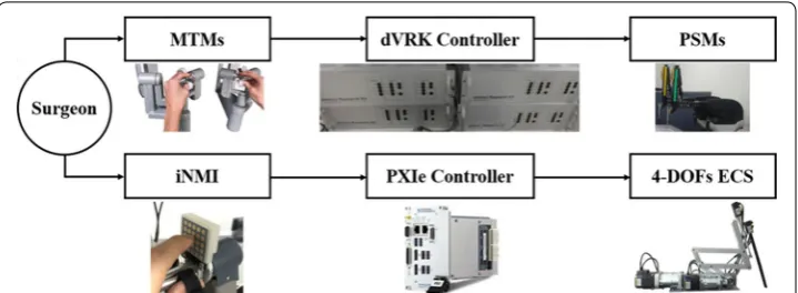
To overcome the above-mentioned limitations, a novel surgical robot system consisting of the following four parts was developed: (i) a simple 3D endoscope that provides 3D vision to the surgeon via a stereo viewer, (ii) a 4-DOFs ECS to control the position of the developed endoscope, (iii) a dVRK-based operating robot system, and (iv) two iNMIs for the surgeon to intuitively control both the 4-DOFs ECS and the PSM simultaneously.
As illustrated in the figure, simultaneous operation of both PSMs and the developed 4-DOFs ECS is enabled via the two MTMs and the two iNMIs. Discontinuous surgical flow can then be overcame. The rolling motion, pitching motion, yawing motion, and translational motion of the 4-DOFs ECS are facilitated by four servo motors (Ezi-Servo Series, Fastech, Bucheon, South Korea).
The simple 3D endoscope
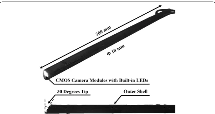
To provide 3D vision to the surgeon and thereby ensure safe robotic surgery, a simple 3D endoscope, which is not included in the dVRK system, was developed explicitly for the laparoscopic surgical robot system. This simple 3D endoscope consists of two CMOS camera modules with six built-in light-emitting diodes (LEDs) and is capable of generat-ing images with a resolution of 640 × 480 pixels, aligned in parallel to procure 3D vision. However, because simply aligning the two image sensors physically does not eliminate distortion or misalignment between the two camera modules, the two acquired images undergo a stereo calibration process, in which the geometric relationship between the two image sensors is calibrated to place them on the same plane, and a stereo rectifica-tion process that places the two calibrated images on a common image plane. These pro-cesses provide precise 3D vision to the surgeon via the stereo viewer. More specifically, the stereo calibration process includes the homography-based and chessboard calibra-tion methods. The former method produces multiple sets of extrinsic parameters and enables calculation of the image sensor’s unique intrinsic and distortion parameters [22]. The latter method further improves the result by using chessboard [22]. Subsequently, stereo rectification is performed to horizontally align the two images and crop the effec-tive image area, after which the reconstructed images are sent to the stereo viewer [23].
Through the above processes, the surgeon obtains 3D vision via the stereo viewer based on the calibrated and rectified images. In addition, the tip of the developed endo-scope is bent at an angle of 30° to enable a wide vision range [24]. The outer case of the simple 3D endoscope is 10 mm in diameter and was manufactured based on rapid pro-totyping techniques (Form 1+ , Formlabs, Somerville, MA, USA) with resolution to the nearest millimeter, as shown in Fig. 2.
The endoscope control system
The 4-DOFs ECS with four controllable joints, J1 to J4, controls the position of the sim-ple 3D endoscope, as shown in Fig. 3. It uses four servo motors to provide the 4-DOFs, comprising rolling motion, pitching motion, yawing motion, and translational motion, to the ECS. Furthermore, a two-parallel link structure was adopted to control the posi-tion of the developed 3D endoscope with optimized fulcrum point moposi-tion, which is nec-essary for laparoscopic robotic surgery. Thus, the fulcrum point motion of the system is guaranteed by its hardware structure, not by a control algorithm. This means that it is able to provide a reliable and fixed fulcrum point motion.
As shown in the figure, the yawing motion of the 3D endoscope is provided by J1 and the pitching motion by J2 based on the bevel gear mechanism that transmits rotational motion at a 90° angle. The translational motion is generated by J3. More specifically, it is accomplished by male and female screw mechanism which converts the rotation motion to the translational motion. Actuation of the motor of J3 rotates the male screw and con-sequently the female screw moves translationally along two parallel line guides placed on either sides of the male and female screw arrangement. The rolling motion is provided by J4, which connects the motor’s shaft and the 3D endoscope via a customized coupler. Thus, the 4-DOFs ECS can perform the translational and fulcrum point motion during surgery by receiving the surgeon’s iNMI control.
The da Vinci research kit
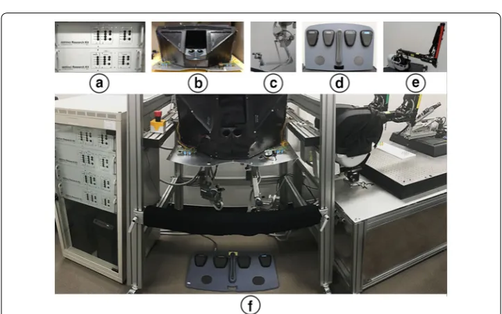
The dVRK system is used as an operating surgical robot system, as shown in Fig. 4. It comprises two PSMs, two MTMs, one foot pedal, and one stereo viewer—which pro-vides 3D stereo view constructed using stereo calibrated and rectified images obtained from the developed 3D endoscope. The two PSMs of the system can be operated using the two MTMs respectively during laparoscopic robotic surgery. The developed 4-DOFs ECS and the 3D simple endoscope are integrated with the dVRK system.
The improved novel master interface
The iNMI, which is a wireless communication interface, intuitively reflects the surgeon’s decision as regards control of the ECS. The iNMI was designed based on the HOTAS concept [2, 20], in which a multi-way switch is employed. To more intuitively reflect the surgeon’s intent, the iNMI utilizes a capacitive touch sensor array, based on a resistor– capacitor (RC) circuit with the capacitor as the touch sensor [25], instead of a multi-way switch. When the user touches the touch sensor, the RC time constant increases as the human body can be regarded as a relatively large capacitor [26]. Further, as the RC time constant can be calculated by setting a new state to the input of the RC circuit and then waiting for the output to be changed to the same state as the input, the touch status of the touch sensor can be determined. The gesture information generated from using the
Fig. 3 4-degrees of freedom (DOFs) endoscope control system (ECS). The fulcrum point motion is achieved by J1 and J2 with its two-parallel link structure. The translational motion and rolling motion are accomplished by J3 and J4, respectively
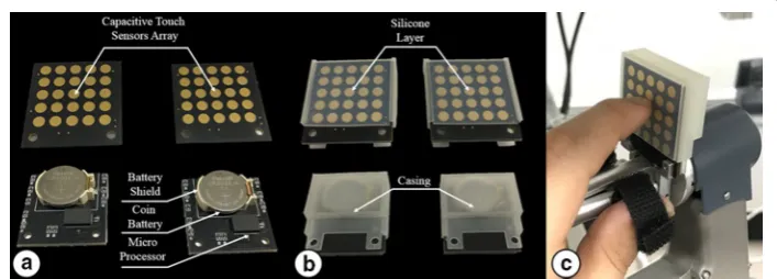
iNMI is obtained via the touch sensors array placed on the front of the iNMI, which comprises 25 capacitive touch sensors, as shown in Fig. 5a. The intent of the surgeon is determined from the touch status of the capacitive touch sensors array. In addition to the capacitive touch sensors array, the iNMI comprises one Arduino-based micro-processor with a Bluetooth low energy radio frequency module (RFD 77101, RFduino, Hermosa Beach, CA, USA), one Li–MnO2 type Lithium button cell battery (CR2032, Panasonic, Osaka, Japan), and several resistors and capacitors to complete the circuit.
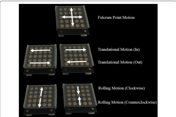
Each capacitive touch sensor is connected to the microprocessor to receive the RC time constant for perceiving the touch status of the capacitive touch sensor. To interpret the received touch information of the touch sensor array, a specific Arduino algorithm was developed to detect gesture information generated by the surgeon, such as upward swipe, downward swipe, forward swipe, and backward swipe. Once the gesture informa-tion is created, the Bluetooth module sends the informainforma-tion to the wireless data receiver, and the received signal is recognized as a command by the controller to manipulate the 4-DOFs ECS. To achieve above functions, a circuit was designed and a printed circuit board including the capacitive sensor array was consequently manufactured. Several parts were used for the board as shown in Fig. 5a. Further, it allows the surgeon to con-trol the iNMI using the index finger that is not used to manipulate the MTM, but only to operate the finger clutch. Each iNMI has dimensions of 33 mm × 35 mm to ensure that they do not disrupt the motion of the MTMs. Furthermore, in order to protect the iNMI’s circuit and the capacitive touch sensor array, a customized outer case was designed and manufactured using a 3D printer and the touch sensor array is covered with a silicone layer, as shown in Fig. 5b. To manipulate the iNMIs simultaneously with the MTMs, the two iNMIs are tightly installed to the two MTMs of the dVRK system using a customized holder, as shown in Fig. 5c. In this way, the operation of the finger clutching the MTM is not interrupted, as occurs when using the da Vinci Si system [27]. Figure 6 shows the mapping information between the iNMI and the 4-DOFs ECS. As can be seen in the figure, the pitching motion and the yawing motion can be controlled by one of the two iNMIs, whereas the rolling motion and the translational motion can only be achieved by a combination of gestures generated by the iNMIs attached on the left and right MTMs. The mapped motions were deliberately designed to be similar to common touch gestures carried out in daily living activities using two fingers to ensure
intuitive control by the surgeon. Thus, the pitching, yawing, rolling, and translation motions of the 4-DOFs ECS can be simultaneously controlled with PSMs by manipulat-ing the two iNMIs and MTMs.
Results
The simple 3D endoscope
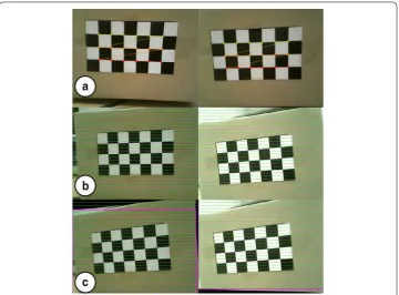
Figure 7 shows the results of the stereo calibration and rectification process using the chessboard. As shown in Fig. 7a, the original images obtained by the two image sen-sors are distorted and misaligned, which means that the surgeon would not be able to comprehend them if they were simply projected onto the stereo viewer. Therefore, the stereo calibration process calculates intrinsic parameters such as distortion coefficients and then the two images are calibrated, as shown in Fig. 7b.
The stereo rectification results can be seen in Fig. 7c. The green lines in the figure are horizontal lines in the images for aligning the two images to the same height. The pink boxes represent the effective image area for stereo view. The effective image area of the obtained images are cropped and reconstructed for providing a clean stereo view to the surgeon.
Figure 8 shows the original images and the final images provided to the surgeon after above processes.
The endoscope control system
The improved novel master interface
Accuracy test
A specific LabVIEWⓇ algorithm, which is able to receive the coordinate information of touched sensor in the array and the generated gesture information, was developed to estimate the precision of the iNMI. This was then achieved by acquiring the data gen-erated by the iNMI which includes touch status of 25 touch sensors in total and the generated gesture motion for controlling the endoscope system, such as upward swipe, downward swipe, forward swipe, and backward swipe. The coordinate of touched sensor and gesture information were tested separately and repeated 50 times. Then, every signal was checked to verify whether the iNMI is able to correctly reflect user’s intent or mis-interpret. No error detected during the repeated tests, which indicates that the iNMI is able to receive the surgeon’s decision with high accuracy.
Data transfer time
To evaluate the latency of the iNMI, the data generated by the iNMI were transferred by both wired communication and wireless communication. Wired communication was used as the reference data transfer time and acquired by physically connecting the iNMI using the universal serial bus port 2.0 type A. Therefore, the data transfer times of both types of communication were recorded using a specific LabVIEWⓇ algorithm. Then, the difference between the arrival times of two data transferred by wired and wireless communication, which can be regarded as latency due to the iNMI’s wireless commu-nication, was calculated. During the test, gesture motion was generated and sent by the iNMI. Furthermore, the gesture information has been encoded into a 1-byte number for
minimizing the data transfer time. The latencies were measured for 50 times and the analysis of the results show that the latency of the iNMI was 5 ms in average, with a standard deviation (SD) of 1 ms.
Power consumption
Since the iNMI is a wireless master interface and therefore only operates based on wireless communication, it is crucial to secure enough power capacity to ensure its effectiveness and full utility during the surgery. To evaluate the power consumption, a LabVIEWⓇ algorithm was developed to continuously intercept the data produced by the iNMI and record the time when there is no any data received, which indicates the iNMI was out of power. Although the power consumption of the iNMI can be calculated
Fig. 8 Comparison between original images and final images. a Original images obtained. b Final images after stereo calibration, rectification, and reconstruction
Table 1 System specifications of the 4-DOFs ECS
DOF degrees of freedom, ECS endoscope control system, iNMI improved Novel master interface
Specification item Unit Joints
Installing posture Floor mounted
Construction Two-parallel link structure
Degrees of freedom 4
Drive method J1–J4 Closed loop stepping system
Operation range ˚ J1 ±45
J2 ±60
J4 ±360
mm J3 160
Maximum speed rpm J1, J2, J4 3000
mm/s J3 50
Resolution /rev. J1, J2 10,000
J4 4000
/mm J3 4000
Entire system’s workspace cm3 20378.3
Master interface iNMI
theoretically, it was tested using the above algorithm in order to practically evaluate the duration time of the iNMI. The tests were performed for 10 times. The results indicate that the iNMI is able to operate for 317 min (SD: 12 min), which is much longer than the average time for several types of robotic surgeries [1, 4, 28, 29]. However, the iNMI can also be used for surgeries which exceed its time duration since the battery can be simply changed to a new one which would cause minimum inconvenience. This implies that the iNMI, which is a wireless master interface and have its own easily replaceable power source, is able to be used for various type of surgeries. The iNMI is safe even when the iNMI battery has no power because it would not send any data that can control the ECS.
Workspace
The workspace of the proposed ECS was calculated based on the hardware design of the system, and compared with the workspace required for cholecystectomy, as shown in Fig. 9. The calculated workspace is 20,378.3 cm3, which exceeds the reference workspace [30] of 549.5 cm3.
Modified peg transfer task
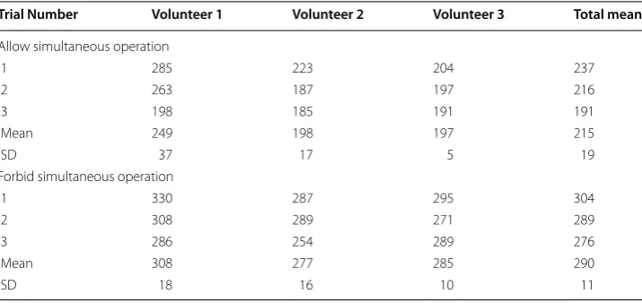
To validate the overall performance of the proposed laparoscopic surgical robot system, a peg transfer task was designed and performed using a newly developed peg trans-fer board redesigned based on the fundamentals of the laparoscopic surgery (FLS) peg transfer kit, as shown in Fig. 10. The peg transfer board was modified because the stand-ard FLS peg transfer bostand-ard does not require the endoscope system to be manipulated owing to its relatively small size, and therefore it is not able to evaluate the proposed surgical robot system consisting of the iNMI, simple 3D endoscope, and ECS, which requires manipulation of the endoscope system. Then, the FLS peg transfer task curricu-lum, which has already been defined in previous research for validation of surgical robot systems and measurement of the surgeon’s technical skills and eye-hand coordination during surgery [2, 20, 31, 32], was performed using the new peg transfer board. Three novice volunteers were recruited for the tasks and followed next steps: (i) the volunteers were asked to transfer six objects from the left side of the board to the right side of the board and (ii) the time taken to transfer the six objects, between the volunteer picking up the first object and releasing the last object, was measured. In addition, during the task, the volunteers were requested to always ensure that all surgical instruments were in view to mimic an actual surgical environment where safety has to be ensured. Fur-thermore, this is also one of the standards to evaluate the robotic surgical skills of the surgeon. The number of surgical instruments obscured from view was also counted dur-ing the experiments. The system setup is shown in Fig. 10. The stereo viewer was used for the task and the obtained calibrated and rectified images projected onto the stereo viewer to provide 3D vision to the users. Same with other studies, the time limit of the experiment was also set to 300 s in spite of the relatively long peg transfer board and use of the stereo viewer [2, 20, 31, 32]. This time limit was also provided by FLS curriculum.
which is the time limit. To evaluate the effectiveness of the iNMI in more detail, a similar peg transfer task was performed by the three volunteers but they were not allowed to manipulate the iNMI and the MTM simultaneously—in order to mimic the swapping of control of the current surgical robot system. The results of the task are summarized in Table 2. As can be seen in Table 2, execution times of the tasks were evidently increased and one volunteer failed to finish the task within the time limit of 300 s. Furthermore, in this case, the surgical instruments were at times out of sight.
Discussion
To enable continuous surgical operation by enabling simultaneous manipulation of the 4-DOFs ECS and PSMs, two iNMIs were installed to two MTMs of the dVRK system.
To estimate the accuracy of the iNMIs, the accuracy test was designed and repeated 50 times where no error was detected. The results of the data transfer time and power con-sumption experiments indicate that the motions of the proposed ECS are in accordance
Fig. 9 Workspace of the proposed 4-DOFs ECS
to the surgeon’s intent in 5 ms via the iNMIs. This can be considered as real time [33], and the power capacity is sufficient for various kinds of surgeries. Moreover, since the power source of the iNMI can be simply replaced, the iNMI is still effective for those surgeries which exceed power volume of the iNMI. These experimental results indi-cate that the iNMI is able to precisely reflect the intent of surgeon and manipulate the 4-DOFs ECS without errors. The iNMI is currently under plan to be directly integrated with MTM of dVRK and communicate with the controller based on wired communica-tion protocol. In this case, the effectiveness and utility of the iNMI is expected to be increased further as the problem of battery consumption and latency will be alleviated.
The developed simple 3D endoscope provides 3D vision by processing the acquired images using a stereo calibration and rectification algorithms. The volunteers recruited for the experiments used the stereo viewer, which displays two stereo images each on its left and right monitors, to obtain 3D vision during the task. All volunteers were able to determine distances and depths of objects on the provided view and execute the experiments.
As illustrated in Fig. 9, the workspace of the 4-DOFs ECS was calculated using its joint information. The shape of the estimated workspace, which is a cone-like shape, indicates the fulcrum point motion of the system. This was stably accomplished by its hardware structure rather than a software algorithm. Therefore, the proposed system provides a reliable and steady fulcrum point motion during robotic surgeries. The 4-DOFs ECS can be used for various kinds of surgeries which have smaller workspaces than that of the cholecystectomy since the system’s workspace is much larger than the cholecystectomy workspace. In addition, the calculated workspace can be further increased by adjust-ing the scale of the 4-DOFs ECS because it is manufactured with a relatively small size compared with the PSM. The resulting mean times of the modified peg transfer tasks were within the time limit of the FLS peg transfer task, even when the longer peg trans-fer board was used for the experiments in order to involve endoscope movements. This demonstrates that good performance is provided by the proposed surgical robot sys-tem using the iNMI, 4-DOFs ECS, and simple 3D endoscope. The gradually decreased execution time of each modified peg transfer task, as shown in Table 2, can be inferred Table 2 Execution time of modified peg transfer task
SD standard deviation
Trial Number Volunteer 1 Volunteer 2 Volunteer 3 Total mean
Allow simultaneous operation
1 285 223 204 237
2 263 187 197 216
3 198 185 191 191
Mean 249 198 197 215
SD 37 17 5 19
Forbid simultaneous operation
1 330 287 295 304
2 308 289 271 289
3 286 254 289 276
Mean 308 277 285 290
which will result in safer robotic surgery environments and decreased operation time. The current 4-DOFs ECS can be only used as research purpose because of its relatively small size compared with actual endoscope system. However, the size of the system can be simply scaled-up to be used for real surgery. The sealing of 4-DOFs ECS is planned to be performed in the future for solving sterility issue [34].
Conclusions
Robot-assisted laparoscopic surgery has high necessity since it provides various advan-tages compared with open surgery and conventional MIS. However, one problem with robotic surgery is the discontinuous surgical flow that occurs when control is being switched between the endoscope system and the PSM to change view and manipulate tools. This leads to problems such as possibility of injury to patients as a result of sur-gical instruments being out of sight, collision between sursur-gical instruments, increased operation time, and enduring of unsatisfactory view to avoid control switching. To rec-tify these problems, this paper presented a wireless controller to simultaneously control the proposed endoscope system consists of a 4-DOFs ECS and a simple 3D endoscope. The 4-DOFs ECS uses four servo motors to generate pitching motion, yawing motion, rolling motion, and translational motion. The fulcrum point motion, which is necessary for the laparoscopic surgical robot system, is achieved by adopting a two-parallel link structure. The workspace of the 4-DOFs ECS is shown to have clinical applicability. The simple 3D endoscope, which has a diameter of 10 mm, was developed using two CMOS camera modules with six built-in LEDs. The two images acquired by the image sensors undergo stereo calibration and rectification to provide a clear stereo vision, and recon-structed stereo images are provided to the user via the stereo viewer of the dVRK system to enable 3D vision during surgery. The design of the proposed wireless master interface was based on the HOTAS concept, called iNMI, enables simultaneous manipulation of the 4-DOFs ECS and the operation robot arm. The results of power consumption tests, latency experiments, and accuracy tests demonstrate that the proposed iNMI is practi-cable and effective. Further, the results of a modified peg transfer task indicate that the proposed system is able to provide continuous surgical operation and therefore remove the issues affecting surgical robot systems. The size of the 4-DOFs ECS can be simply scaled-up for being used in clinics and the sealing issue will have to be resolved in order to overcome sterility issue.
Abbreviations
manipulator; CMOS: complementary metal–oxide–semiconductor; HOTAS: hands-on-throttle-and-stick; LED: light-emit-ting diode; RC: resistor–capacitor; SD: standard deviation; FLS: fundamentals of laparoscopic surgery.
Authors’ contributions
MK proposed the entire system of 3D endoscope system and the iNMI for wireless control and conducted experiments with CL. NH and YJK recommended system setup for the experiments. SK suggested HOTAS concept and supervised all research activities. HJK advised for mechanical issues related to the proposed surgical robot system. All authors read and approved the final manuscript.
Author details
1 Interdisciplinary Program for Bioengineering, Graduate School, Seoul National University, Seoul 03080, South Korea. 2 Korea Electrotechnology Research Institute, Ansan 15588, South Korea. 3 Institute of Medical and Biological
Engineer-ing, Seoul National University, Seoul 08826, South Korea. 4 Department of Biomedical Engineering, Seoul National
University College of Medicine, Seoul 03080, South Korea. Acknowledgements
Not applicable. Competing interests
The authors declare that they have no competing interests. Availability of data and materials
All data generated or analyzed during this study are included in this published article. Funding
This work was supported by the Research Program 2016 funded by Seoul National University College of Medicine Research Foundation (Grant No. 800-20160072), a grant from Seoul National University Hospital (2017), the National Research Foundation of Korea grant funded by the Korea government (MSIP) (Grant 2017R1A2B2006163), and Global Ph. D. Fellowship Program through the National Research Foundation of Korea funded by the Ministry of Education (Grant 2014H1A2A1020384). The da Vinci Research Kit was donated by Intuitive Surgical, Inc. (Sunnyvale, CA, USA) in 2014.
Publisher’s Note
Springer Nature remains neutral with regard to jurisdictional claims in published maps and institutional affiliations.
Received: 4 April 2017 Accepted: 20 June 2017
References
1. Pahwa M, Pahwa AR, Girotra M, Abrahm RR, Kathuria S, Sharma A. Defining the pros and cons of open, conventional laparoscopy, and robot-assisted pyeloplasty in a developing nation. Adv Urol. 2014;2014:850156.
2. Lee C, Park WJ, Kim M, Noh S, Yoon C, Lee C, et al. Pneumatic-type surgical robot end-effector for laparoscopic surgical-operation-by-wire. Biomed Eng Online. 2014;13:130.
3. Bell MC, Torgerson J, Seshadri-Kreaden U, Suttle AW, Hunt S. Comparison of outcomes and cost for endome-trial cancer staging via traditional laparotomy, standard laparoscopy and robotic techniques. Gynecol Oncol. 2008;111(3):407–11.
4. Kang BH, Xuan Y, Hur H, Ahn CW, Cho YK, Han S-U. Comparison of surgical outcomes between robotic and laparo-scopic gastrectomy for gastric cancer: the learning curve of robotic surgery. J Gastric Cancer. 2012;12(3):156–63. 5. Sung GT, Gill IS. Robotic laparoscopic surgery: a comparison of the da Vinci and Zeus systems. Urology.
2001;58(6):893–8.
6. Corcione F, Esposito C, Cuccurullo D, Settembre A, Miranda N, Amato F, et al. Advantages and limits of robot-assisted laparoscopic surgery: preliminary experience. Surg Endosc. 2005;19(1):117–9.
7. Lanfranco AR, Castellanos AE, Desai JP, Meyers WC. Robotic surgery: a current perspective. Ann Surg. 2004;239(1):14–21.
8. Hannaford B, Rosen J, Friedman DW, King H, Roan P, Lei C, et al. Raven-II: an open platform for surgical robotics research. IEEE Trans Biomed Eng. 2013;60(4):954–9.
9. Heemskerk J, Bouvy ND, Baeten CG. The end of robot-assisted laparoscopy? A critical appraisal of scientific evidence on the use of robot-assisted laparoscopic surgery. Surg Endosc. 2014;28(4):1388–98.
10. Sullivan MJ, Frost EA, Lew MW. Anesthetic care of the patient for robotic surgery. Middle East J Anesthesiol. 2008;19(5):967–82.
11. da Vinci surgery: minimally invasive surgery. http://www.davincisurgery.com/assets/docs/da-vinci-surgery-fact-sheet-en-1005195.pdf?location=1&version=b.pdf. Accessed Mar 2017.
12. Gomez JB, Ceballos A, Prieto F, Redarce T. Mouth gesture and voice command based robot command interface. IEEE international conference on robotics and automation (ICRA), 12–17 May. 2009. p. 333–8.
13. King BW, Reisner LA, Pandya AK, Composto AM, Ellis RD, Klein MD. Towards an autonomous robot for camera control during laparoscopic surgery. J Laparoendosc Adv Surg Tech. 2013;23(12):1027–30.
14. Nishikawa A, Hosoi T, Koara K, Negoro D, Hikita A, Asano S, et al. FAce MOUSe: a novel human–machine interface for controlling the position of a laparoscope. IEEE Trans Robot Autom. 2003;19(5):825–41.
• We accept pre-submission inquiries
• Our selector tool helps you to find the most relevant journal • We provide round the clock customer support
• Convenient online submission • Thorough peer review
• Inclusion in PubMed and all major indexing services • Maximum visibility for your research
Submit your manuscript at www.biomedcentral.com/submit
Submit your next manuscript to BioMed Central
and we will help you at every step:
23. Zou L, Li Y. A method of stereo vision matching based on OpenCV. International conference on InAudio language and image processing (ICALIP), 23–25 Nov. 2010. p. 185–90.
24. Peter JH, Ellison EC, Innes JT, Liss JL, Nichols KE, Lomano JM, et al. Safety and efficacy of laparoscopic cholecystec-tomy. A prospective analysis of 100 initial patients. Ann Surg. 1991;213(1):3.
25. Kyriakis-Bitzaros ED, Stathopoulos NA, Pavlos S, Goustouridis D, Chatzandroulis S. A reconfigurable multichannel capacitive sensor array interface. IEEE Trans Instrum Meas. 2011;60(9):3214–21.
26. Vandenberghe L, Boyd S, El Gamal A. Optimizing dominant time constant in RC circuits. IEEE Trans Comput Aided Des Integr Circuits Syst. 1998;17(2):110–25.
27. Monika EH, Hubert S, Myriam JC. Robotics in general surgery. In: Kim KC, editor. Introduction to the Robotic System. New York: Springer; 2014. p. 9–15.
28. Sung GT, Gill IS, Hsu TH. Robotic-assisted laparoscopic pyeloplasty: a pilot study. Urology. 1999;53(6):1099–103. 29. Choi WK, Kim JK, Yang JB, Ko YB, Nam SL, Lee KH. Two-port access versus four-port access laparoscopic ovarian
cystectomy. Obstet Gynecol Sci. 2014;57(5):379–85.
30. Liu D, Li J, He C, Kong K. Workspace analysis based port placement planning in robotic-assisted cholecystectomy. Int Symp IT Med Educ. 2011;9–11:616–20.
31. Shin WH, Kwon DS. Surgical robot system for single-port surgery with novel joint mechanism. IEEE Trans Biomed Eng. 2013;60(4):937–44.
32. Joseph R, Goh A, Cuevas S, Donovan M, Kauffman M, Salas N, et al. Chopstick surgery: a novel technique improves surgeon performance and eliminates arm collision in robotic single-incision laparoscopic surgery. Surg Endosc. 2010;24(6):1331–5.
33. Haidegger T, Kovács L, Precup RE, Benyó B, Benyó Z, Preitl S. Simulation and control for telerobots in space medicine. Acta Astronaut. 2012;81(1):390–402.