Published By :Universal Multidisciplinary Research Institute Pvt Ltd
THE OPTICAL MOUSE AS A TWO-DIMENSIONAL
DISPLACEMENT SENSOR BOT AND GRAPHICAL
POSITIONER
Vishweshwer Shastri1, Bhim Singh2, Monalisa Biswas3
B.E in Applied Electronics & Instrumentation Engineering-2013
THE UNIVERSITY OF BURDWAN.
Email: [email protected] , [email protected], [email protected]
_________________________________________________________________________________________________________________
ABSTRACT:
An optical mouse is used exclusively for displacement measurement. A cost effective optical displacement sensor will be invaluable in application where very high resolution are not required. In this work the optical mouse has been investigated to determine its suitability for two-dimensional displacement measurement while the mouse works only on opaque surfaces.
The mouse connected to the computer uses the supply from the computer as its Vcc, which is 5 Volts. The mouse has been configured into a robot. The objective of the project is to obtain the graphical position of the mouse when interfaced with the computer through a USB port. A MATLAB program is employed in-order to continuously monitor the robot positions. The robot motion is in corresponding to the obstacle it senses, wherein it changes its direction of motion on sensing an obstacle.
Introduction:
A wide variety of displacement sensors have been developed based on the principles of capacitive, inductive, magnetic, ultrasonic and optical sensing. For displacement sensors based on the optical effect alone, designs have been reported employing the principles of triangulation, interferometry, moiré , diffraction, time-of-flight, and speckle . Some of these schemes are able to provide measurements with sub-micrometer accuracy. Nevertheless, not all applicationsrequire such high degrees of measurement accuracy. In building drift monitoring and large-strain viscoelastic measurements, for example, mensuration in the range of0.1mm are generally sufficient. One major drawback with the majority of optical displacement measuring tools lies with their relative high cost. This arises primarily fromthe expensive components used in certain designs and the non-economics of scale associated with low volume manufacturing of such systems. There is, hence, an incentive to source for alternative cost-effective optical sensors for displacement measurement; in particular, when the
rollers located within the mouse are in constant contact with the rubberized ball. One of the rollers detects for motion in the x-direction, whereas the other detects for motion in the y-direction. Quite naturally, the mechanical mouse suffers from the problems of wear and dirtaccumulation over time. For this reason, it is common to find them incapable of registering movement after several months of heavy usage. In 1999, Agilent Technologies unveiled the first optical mouse that was immune to the problems of wear and dirt accumulation. With resolutions currently reaching 0.03175 mm, optical mice are gradually replacing their mechanical predecessors as the pointing device of choice in computers. Due to the economics of large volume production, the cost of an optical mouse is extremely low. Currently, it is possible to acquire a reasonably good quality unit for as low as US$ 20. In
this work, the suitability of the optical mouse as an optical displacement sensor is first investigated. Next, it is demonstrated in an experiment to determine viscoelastic deformation of polyethylene. The general behavior of solids is one that exhibits an elastic response to external forces. Fluids, on the other hand, are generally categorized as exhibiting a viscous response to applied forces. Materials like polymers, however, exhibit both an elastic and viscous response to external forces. Such hybrid behavior is described as viscoelasticity. While the viscoelastic behavior of materials is well studied , it is still actively researched due to its importance in a wide spectrum of engineering applications . Optical methods to determine the viscoelastic deformation of materials have often relied on expensive and complicated designs. .
THE OPTICAL MOUSE
The mouse is a human interface device for a personal computer. The movement of the device is measured and results in a displacement of the mouse pointer on the screen. In this report we only consider contactless optical mice because a trackball or the conventional mouse, with a rolling rubber ball on the surface, are not contactless . The optical mouse uses, as implicated by its name, an optical device to measure displacement. The measuring system has no moving parts, does not make contact with the surface, and needs no maintenance.
Components of an optical mouse:
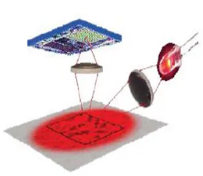
The optical system consists mainly of three parts :
Lens
Light source
Sensor.
These three parts are assembled on a custom base plate, i.e. Printed Circuit Boards (PCB), and the clip. The lens is the largest part and is mounted on the base plate of the mouse. It transports the light from the light source towards the surface to be measured and projects a
surface image on the mouse sensor. In Figure 2 this is shown schematically and Figure 3. shows
the actualoptical path in an assembled optical
mouse.
Fig.3 Optical system in use.
The light source is either a LED (Light Emitting Diode) or a VCSEL (Single- ModeVertical-Cavity Surface Emitting Laser). The mouse sensor takes gray scale images of the underlying surface. These images vary from 16×16 pixelsto 30 × 30 pixels, depending on the image sensor used. Image detail does not onlydepend on the image size but also
depends on lens quality and the wavelength and corresponding colour of the light
source. The light colourcan affect the contrast of the surface image: for instance details a r e better recognized with red light, than with blue light for instance. In Figure 4. The relative response of the mouse sensor, to different wavelengths (light colours), is shown. Table 1 shows the wavelengths and corresponding colours, the available LED’s and their operating wavelength’s are arranged by colour.
Table:1
The response of the ADNS-3080 mouse sensor is taken as an example. A red LED with a wavelength of approximately 630 nm gives maximum response. This LED is also very efficient power-wise, therefore this is the most commonly used light source in optical mice. In an optical laser mouse, t h e VCSEL
uses awavelength of approximately 830 nm (near infrared).The relative response at this wavelength is lower than the relative response at a wavelength of 630 nm.
The mouse sensor: T he mouse sensor is an
integrated circuit that contains an Image Acquisition
System (IAS), a Digital Signal Processor (DSP) and a serial port for communication. The mouse sensor controls the entire optical system including the L E D or VCSEL. The IAS is the final part of the optical system.In this componentthe image of the underlying surface is transformed into a n electrical signal that represents the actual image. This signal can contain from 256 bytes for a 16×16 pixel image to 900 bytes for a n 30×30 pixel image, depending on the size of the IAS. The electrical signals of the images are processed in the DSP. The DSP measures changes in position by comparing the sequentially taken images of t h e surface. From the differences between the two images a position change can be calculated. This results in a direction and distance of the displacement which give the relative displacement values _x and _y. The program to compare and calculate the relative displacement, the mouse sensor program, is provided by the mouse sensor manufacturer. The microcontroller reads the _x and _y information. The mouse sensor connects with this microcontroller
v i a serial port. The serial port is a four wire synchronous serial port for communication with a m i c r o controller and has the following connections:
• SCLK: Clock input, always generated by the microcontroller.
• MOSI: Input data (Master Out/ Slave In). • MISO: Output data (Master In/ Slave Out). • NCS: Chip select input (active low).
is according to the serial communication protocol.
The microcontroller:
The second Integrated circuit in the mouse contains a microcontroller: an
EEPROM which contains the firmware and the mouse s e n s o r program, memory (RAM), an internal timer and a U S B Engine. Only if a mouse event has occurred, like mouse movement or the pressing of a button, the mouse sends data to the personal computer (PC) . Table 2. shows an example of transmitted data in 8 bits/axis data format. The transmitted data has the f o l lowing
format: The first byte contains the button position The value of th most significant b i t (MSB) is always 1, the remaining 7 bits are 0 if t h e corresponding button is pressed or 1 if the corresponding button is released. In byte number 1 of Table 3. This is shown for a three button
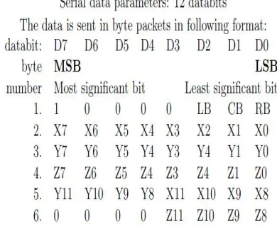
Table 2: Package data format
Table 3: Package data format.
mouse. The second byte contains the x-displacement. The third byte contains the y-displacement. The
fourth byte sends the z-displacement in case the mouse has a scroll wheel.
All the displacement data is insigned byte format (from −128, +127) . A posi ve value is
movement in upwards direction or to the right.The motion is the point of interest, but button and scroll wheel movement belong to the data set. The buttons will be used to be able to start and stop the measurement. In later stage other digital sensors that act similar as a switch could be connected. A fast mouse movement, results in a great displacement between two data
sets. More bits/axis mean the mouse can operate at a higher velocity which is important for a gaming mouse.Therefore some mice use also 12 or even 16 bits/axis to be able to send more displacement data at a time. Because a byte has only 8 bits, the remaining bits of the 12 and 16 bits data formats have to be send in another byte. This is established by sending the remaining displacement data in a second series of 8 data bits. The data shown in Table5 shows an extra fifth byte for 12 bits/axis 4 bits (D0 to D3 of byte number 5 become D8 to D11 together with byte number 2) 5 for x-displacement,and 4 bits (D4 to D7 of byte number 5 become D8 to D11 together with byte number 3) f o r y-displacement. I n case of 16 bits/axis the fifth byte would be used for the x0- displacement bits (D0 to D7 of byte number 5 become D8 to D15 together with byte number 2) and the sixth byte would be used for the y0−displacement (D0 to D7 of byte number 6
.
PIN Configuration for A2836G IC
General description
The optical CMOS sensor provides a non mechanical engine for implementing a computer mouse. On a CMOS chip the images are captured, digitized, and then digitally processed. Using an optical navigation technology, the sensor measures changes in position by optically acquiring sequential surface images (frames) and mathematically determining the direction and magnitude of movement. The sensor is mounted
Electrical characteristics: [a] operating conditions:
Timing and state diagram: Quadrature output waveform:
Application circuit:
Published By :Universal Multidisciplinary Research Institute Pvt Ltd Hardware design and Installation:
Objective:
The objective of the project is to continuously monitor the co-ordinate positions of the robot, connected to the computer via USB port. And obtain the corresponding readouts on the computer screen. Pre-requisite knowledge:
Programming in MATLAB. Components used:
1. An Optical mouse with an USB connection. 2. IR Obstacle detector (proximity sensor) 3. IC-L293D
4. Two motor (6-12 Volts).
Working principle of the various components: 1. An optical mouse sensor:
This is the basic component of the project. Its working is explained in the document earlier.
2. IR obstacle detector (proximity sensor) : This sensor is ideal to detect an object by means of no-contact. The sensor uses a TSOP sensor which is commonly used in TVs, DVDs, and e.t.c. This is a digital sensor and provides high output, whenever it detects an object. The detecting distance can be varied by tuning the onboard potentiometer fodesied range. Its operating range is 4.5 to 5 Volts.
3. Quadruple Half-H bridge IC – L293D:
The L293D is a quadruple h i g h -current half-H driver. The L293D is designed t o provide bidirectional drive currents of up to 600 – mA at voltages from 4.5 V to 36 V. T h e
device is designed to drive inductive loads such as relays, solenoids, dc and bipolar stepping motors, as well as other high-current / high - voltage loads in positive supply applications.
All inputs are TTL compatible. Each output is a complete tot e m – p o l e drive circuit, with a D a r l i n gton transistor s i n k and a p s e u d o - D a r l i g t o n source. Drivers are enabled in pairs, with drivers 1 and 2 enabled by 1,2EN and drivers 3 and 4 enabled by 3,4EN. W h e n an enable input is high, t h e associated drivers are enabled, and their outputs are active a n d in phase with their inputs. When the enable input islow, those drivers are disabled, and their outputs are o f f and in the high-impedance state. W i t h the proper data inputs, each p a i r o f drivers forms a full-H (or bridge) reversible drive suitable for solenoid o r motor applications.
L293D - IC
On the L293D, external high-speed output clamp diodes should be used for inductive transient suppression.
Published By :Universal Multidisciplinary Research Institute Pvt Ltd Logic diagram of the IC
Schematic of I/Os of L293D
Published By :Universal Multidisciplinary Research Institute Pvt Ltd Data analysis:
Mouse moved in the direction of SW at 237.7721 degrees. Distance: 0.1037 Mouse moved in the direction of SW at 236.432 degrees. Distance: 0.13335 Mouse moved in the direction of SW at 231.7612 degrees. Distance: 0.011168 Mouse moved in the direction of SW at 248.4951 degrees. Distance: 0.0062855 Mouse moved in the direction of SW at 255.2824 degrees. Distance: 0.0090695 Mouse moved in the direction of SW at 231.7612 degrees. Distance: 0.0037227 Mouse moved in the direction of SW at 248.4951 degrees. Distance: 0.0062855 Mouse moved in the direction of SW at 248.4951 degrees. Distance: 0.0062855 Mouse moved in the direction of SW at 248.4951 degrees. Distance: 0.0062855 Mouse moved in the direction of S at -90 degrees. Distance: 0.005848
Mouse moved in the direction of SW at 251.339 degrees. Distance: 0.021604 Mouse moved in the direction of S at -90 degrees. Distance: 0.017544
Mouse moved in the direction of SW at 258.8552 degrees. Distance: 0.011921 Mouse moved in the direction of S at -90 degrees. Distance: 0.011696
Mouse moved in the direction of S at -90 degrees. Distance: 0.002924 Mouse moved in the direction of S at -90 degrees. Distance: 0.002924 Mouse moved in the direction of S at -90 degrees. Distance: 0.002924 Mouse moved in the direction of S at -90 degrees. Distance: 0.002924 left Mouse Button Down at X = 0.319124 Y = 0.668129
Mouse is dragged.
left Mouse Button Up at X = 0.319124 Y = 0.668129
Mouse moved in the direction of E at 0 degrees. Distance: 0.0023041 Mouse moved in the direction of E at 0 degrees. Distance: 0.0023041 Mouse moved in the direction of E at 0 degrees. Distance: 0.0092166 Mouse moved in the direction of E at 0 degrees. Distance: 0.0046083 Mouse moved in the direction of E at 0 degrees. Distance: 0.0046083 Mouse moved in the direction of E at 0 degrees. Distance: 0.0046083 Mouse moved in the direction of E at 0 degrees. Distance: 0.0023041 Mouse moved in the direction of E at 0 degrees. Distance: 0.0023041 Mouse moved in the direction of E at 0 degrees. Distance: 0.0023041 Mouse moved in the direction of E at 0 degrees. Distance: 0.0046083 Mouse moved in the direction of E at 0 degrees. Distance: 0.0023041 Mouse moved in the direction of E at 0 degrees. Distance: 0.0046083 Mouse moved in the direction of E at 0 degrees. Distance: 0.0023041 Mouse moved in the direction of E at 0 degrees. Distance: 0.0023041 Mouse moved in the direction of E at 0 degrees. Distance: 0.0023041 left Mouse Button Down at X = 0.372120 Y = 0.668129
Mouse is dragged.
left Mouse Button Up at X = 0.372120 Y = 0.668129 right Mouse Button Down at X = 0.372120 Y = 0.668129 Mouse is dragged.
right Mouse Button Up at X = 0.372120 Y = 0.668129
Mouse moved in the direction of N at 90 degrees. Distance: 0.002924 Mouse moved in the direction of N at 90 degrees. Distance: 0.005848
Published By :Universal Multidisciplinary Research Institute Pvt Ltd Conclusion:
A thorough analysis and a dedicated setuphas been instrumental to demonstrate the optimized usage of the optical mouse as a displacement sensor and the graphical co-ordinate positioner. We hence conclude that the sensitivity of the mouse is good and can help us to yield a cost effective locating device.
The optical sensor with an LED light source as used in the demonstration turns out to be serene. The sensor works in a height range of 0.5 mm to 2.5 mm.
Therefore this concept can be brought into application wherein very accurate measurements are not required. This ultimately would help economically and yield better results.