A Quarterly Publication of Neuroscience Departments in:
Tehran University of Medical Sciences Shahid Beheshti University of Medical Sciences Shahed University & Iran University of Medical Sciences
& Iranian NeuroScience Society (INSS)
Chairman and Editor-in-Chief: Mohammad Taghi Joghataei, PhD Cellular and Molecular Research Center, and Neuroscience Department, Iran University of Medical Sciences, Tehran, Iran
Associate Editor: Hamed Ekhtiari, MD Translational Neuroscience Program Institute for Cognitive Sciences Studies, Iran
Section Editors:
Cellular and Molecular Neuroscience: Masoud Shekarabi, PhD University of Montreal, Canada
Cognitive Neuroscience: Ali Yoonessi, MD, PhD Tehran University of Medical Sciences, Iran
Computational Neuroscience: Mohammad R. Daliri, PhD Iran University of Science and Technology, Iran
Behavioral Neuroscience: Abbas Haghparast, PhD Shahid Beheshti University of
Medical Sciences, Iran Behavioral Neuroscience Co - Editor:
Ali Shahbazi, PhD Iran University of Medical Sciences, Iran
Editorial Board:
Shahin Akhondzadeh, PharmD, PhD Tehran University of Medical Sciences, Iran Abolhassan Ahmadiani, PharmD, PhD Shahid Beheshti University of Medical Sciences, Iran
Hasan Ashayeri, MD Iran University of Medical Sciences, Iran
Mazyar Azar, MD Tehran University of Medical Sciences, Iran Tourandokht Baluchnejadmojarad, PhD
Iran University of Medical Sciences, Iran Sanju George, MD
Birmangham & Solihull Mental Health NHS Fodtion, UK Ali Gorji, MD, PhD
Munster University, Germany Gholamreza Hasanzadeh, PhD Tehran University of Medical Sciences, Iran
Richard Hawkes, PhD Calgary University, Canada Mitsuhiro Kavata, MD, PhD Perfetural Medical University, Japan
Alireza Khoshnevisan, MD Tehran University of Medical Sciences, Iran
Mahmoud Kiaei, PhD University of Arkansas for
Medical Sciences, USA Mehdi Mehdizadeh, PhD Iran University of Medical Sciences, Iran
Masoud Mehrpour, MD Iran University of Medical Sciences, Iran
Esmail Meisami, PhD University of Illinois, USA Hamidreza Mostafawi Abdolmaleki, MD
Harvard University, USA Fereshteh Motamedi, PhD
Shahid Beheshti University of Medical Sciences, Iran
Arezo Nahavandi, MD, PhD Iran University of Medical Sciences, Iran
Klaus Obermayer, PhD Technische Universität Berlin, Germany
Amir H. Rezvani, PhD Duke University, USA Ali Rashidi Pour, PhD Semnan University of Medical Sciences, Iran
Mehrdad Roghani, PhD Shahed University, Iran Jacqueline Sagen, PhD University of Miami, USA Esmaeil Shahsavand Ananloo MD., PhD
Tehran University of Medical Sciences Amir M. Sodagar, PhD University of Michigan, USA Hamid Soltanian Zadeh, PhD
Tehran University, Iran Mark J. West, PhD Aarhus University, Denmark Mohammad Reza Zarrindast, PharmD, PhD
Tehran University of Medical Sciences, Iran
Executive Board: Sobhan Rezaee, MA Allame Tabatabaei University, Iran
Ali Shahbazi, PhD Iran University of Medical Sciences, Iran
Proof Reading Editors: Nima Khlighinejad, MD
Shiva Alinaqian, MA Mohammad Torabi Nami, PhD
Elham Golpoosh, MA Graphic & Layout Designer:
Haleh Ghorbani Tehrani Cover Designer: Mohsen Farhadi, Naeem Tadayon
Editorial Office:
Neuroscience Section, School of Medicine, Hemmat Campus, Iran University of Medical Sciences,
Shaheed Hemmat Highway, Tehran, P.O. Box: 15144-6183, Islamic Republic of Iran.
Tel: +98-21-82944576/Fax:+98-21-88622709 Website: http: //bcn.tums.ac.ir
Email: [email protected]
Disclaimer: While the information in this journal are lieved to be true and accurate at the date of its publication, neither the authors, the editors, nor the publisher can cept any legal responsibility for any errors or omissions that maybe made. The publisher makes no warranty, express or
implied, with respect to mate rial contained herein. Copyright © 2013 by School of Medicine,
Tehran University of Medical Sciences Published in Tehran University of Medical Sciences in Cooperation with Mehromah-e-No Publication Institute
Tehran University of Medical Sciences
Drug Control
Head Quarter UniversityShahed
Shahid Beheshti University of Medical Sciences
EDITORIAL
RESEARCH PAPERS
Implantable Microsystems for High-Resolution Interfacing to the Brain
4 Sodagar, A.M.
The Effects of Bilateral Subthalamic Nucleus Stimulation on Cognitive and Neuropsychiatric Functions in Parkinson’s Disease: A Case-Control Study
Mahdavi, R., Malakouti, S.K., , Shahidi, Gh.A., Parvaresh-Rizi, M.
35
COMMENTARY
The Polarity-Dependent Effects of the Bilateral Brain
Stimulation on Working Memory Keshvari, F., Pouretemad, H.R., Ekhtiari, H. 42
Restoring Motor Functions in Paralyzed Limbs through Intraspinal Multielectrode Microstimulation Using Fuzzy Logic Control and Lag Compensator
Roshani, A., Erfanian, A. 50
Evaluation of the Endothelial Cell Antibodies in Serum and Perilymphatic Fluid of Cochlear Implanted Children with Sensorineural Hearing Loss
Farhadi, M., Noorbakhsh, S., Tabatabaei, A., Daneshi, A., Ghavidel Darestani, S., Jomeh, E.
62
Comparing the Anticonvulsant Effects of Low Frequency Stimulation of Different Brain Sites on the Amygdala Kindling Acquisition in Rats
Esmaeilpour, KH., Masoumi-Ardakani, Y., Sheibani, V., Shojaei, A., Harandi, SH., Mirnajafi-Zadeh, J.
68
Methodological Dimensions of Transcranial Brain
Stimulation with the Electrical Current in Human Rostami, M., Golesorkhi, M., Ekhtiari, H. 8
Cheap Technology Like Transcranial Direct Current Stimulation (tDCS) Could Help in Stroke Rehabilitation in South Asia
Bashir, SH., Yoo, W.K. 6
Treatment of Neurological and Psychiatric Disorders with Deep Brain Stimulation; Raising Hopes and Future Challenges
Sharif Sharifi, M. 84
Repetitive Transcranial Magnetic Stimulation (rTMS) in the Management of Alcohol Dependence and other Substance Abuse Disorders – Emerging Data and Clinical Relevance
De Sousa, A. 89
Corticospinal Facilitation of Erector Spinae and Rectus Abdominis Muscles During Graded Voluntary Contractions is Task Specific: A Pilot Study on Healthy Individuals
Jaberzadeh, SH., Zoghi, M., Morgan, P., Storr, M. 27
Non-Invasive Brain Stimulation for Enhancement of
Corticospinal Excitability and Motor Performance Jaberzadeh, SH., Zoghi, M. 75
lmost a decade after the invention of the
first semiconductor transistor in 1948, it
took the revolutionary technology almost a decade to evolve from producing single devices to integrating only a few transistors
as the first integrated circuit (IC) in 1958. Since then,
integrated circuits have been in continuous progress for more than half a century as predicted by the well-known
Moore’s law. While integrated circuits still continue their progress with the same exponential pace, it is almost a
decade that a new branch of science and technology has
emerged, known as integrated microsystems. This can
be taken as the natural technological evolution from in-dividual circuit chips and non-circuit modules to com-plete systems with small physical dimensions and light
weight. Integrated microsystems have opened windows of hope to providing efficient solutions to some of the
problems that have not been resolvable by any other
means whatsoever.
Among many kinds of microsystems being developed
for a wide variety of applications, such as automotive industry, aerospace engineering, environmental monitor
-ing, and defense systems, implantable biomedical micro -systems are of increasing interest to both medical and
engineering communities. This is mainly because of the
capabilities such devices are expected to provide on the
medical side, and also the technical challenges available on the engineering side. Examples of biomedical im
-plants are pacemakers, cochlear im-plants, neural record
-ing microsystems, and deep brain stimulators.
Electrically interfacing with the nervous system goes
back to Benjamin Franklin’s works no more than 250
years. Intra-cortical interfacing with the brain with high
density and at the same time with high spatial resolution
is, however, a rather new concept, being made possible
by using unique capabilities advanced microtechnology
has to offer. This technology is capable of implement -ing complex circuits with up to millions of transistors
on silicon chips as small as a few millimeters on a side,
realizing non-electronic structures such as probes and
electrodes with sub-micron fabrication resolution, and finally integrating and packaging of all the electronic and
non-electronic parts required to make a tiny implantable
microsystem.
Implantable neural interfacing microsystems are
known as powerful tools to enable neuroscientists per-form high-density intra-cortical studies in the order of
tens to hundreds and even thousands of parallel channels,
and with high spatial resolution in the order of hundreds
to tens of micrometers and even finer. It is also believed
that such devices can successfully treat neural disorders
such as epilepsy, paralysis, and Parkinson’s disease, and even help effectively overcome deafness and blindness. On the non-medical side, researchers in cognitive sci -ences are among the other groups that anxiously await
fully functional neural interfacing implants, using which
they can talk to the brain and learn about how the signals
sensed from the outside world are recognized.
Implantable microsystems designed and developed
for intra-cortically interfacing with the central nervous system can be considered among the most sophisticated
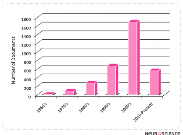
types of biomedical implants, possessing perhaps the most interesting applications. The extent of interest at
-tracted to research in this area is clearly reflected in the
daily increasing number of publications on the design
and application of such devices. As evidence, Fig. 1
shows the exponential-like growth of papers and other
relevant scientific and technical documents being pub
-lished. This plot is the result of a search over Elsevier
Scopus database for documents of any type with the
words ‘microsystem’ and ‘neural’ in their titles, ab
-stracts, or keywords.
An implantable neural interfacing microsystem, in general, comprises a microelectrode array (MEA), an
analog front-end interfacing with the target tissue for
recording and stimulation, and a radio frequency (RF) front-end for wireless interfacing to the external world. In order to be fully implantable, a neural interfacing mi
-crosystem needs to fulfill the following requirements:
Small physical size–No matter how powerful it is, it is
evident that a microsystem needs to be small enough in size in order to be implanted in the brain without
consider-able damage to neighboring organisms and living tissues.
Editorial:
Implantable Microsystems for High-Resolution Interfacing
to the Brain
Wireless operation–An implantable microsystem
needs to bidirectionally communicate to an external
set-up through wireless connection. Programming a neural interfacing implant to operate in the proper mode, setting parameters such as amplification gain and bandwidth for
recording and the details stimulation pulses for
stimula-tion necessitate the flow of data from the external side to the implant. In the reverse direction, one needs to trans -fer recorded neural data from the implant to the external
setup, too.
Packaging– Electronic circuitry in an implant, need to
be properly packaged and sealed in order to be protected from undesired chemical and electrochemical
interac-tions with their surroundings. Moreover, packaging of
an implant is sometimes necessary in order to protect the
living body from the toxic materials used in the implant.
Biocompatibility–It is also of crucial importance to
avoid bringing materials in touch with the body that might
cause irritation, inflammation, or any other undesired reactions by the body. Even if the materials used for the development of an implant are not toxic, it is important
to avoid unwanted reactions the body might show to the
implant as a foreign object. For these reasons, implant -able microsystems are either made out of biocompatible
materials such as silicon, titanium, platinum, or gold, or encapsulated with materials such as silicone and parylene.
Over the past few decades, depth and breadth of re
-search on the design, development, and employments of
implantable neural interfacing microsystems has been
expanding with an admirably rapid pace. These devices
are expected to revolutionalize research in the near
fu-ture not only in basic and clinical neuroscience, but also in so many other application areas.
References
B. Franklin, “An account of the effects of electricity in paralytic cases,” Phil. Trans. Lond., vol. L, pp. 481–483, 1759.
K.D. Wise, A.M. Sodagar, Y. Yao, M.N. Gulari, G.E. Perlin, and K. Najafi, “Microelectrodes, Microelectronics, and Implant-able Neural Microsystems,” Proceedings of the IEEE, vol. 96, no. 7, pp. 1184-1202, July 2008.
Amir M. Sodagar, Ph.D.
Faculty of Electrical and Computer Engineering, K.N.Toosi University of Technology, Tehran, Iran
Electrical Engineering and Computer Science Department, University of Michigan, Ann Arbor, MI, USA,
School of Cognitive Sciences, Research Institute for Research in Fundamental Sciences, Tehran, Iran
Ecole Poytechnique de Montreal, Montreal, QC, Canada E-mail: [email protected]
ear Editor, Stroke is caused by a disturbance
in the supply of blood to the brain due to
vascular pathology, thereby exhibiting a
loss of brain function related its vascular
territory. Stroke can be either ischemic or hemorrhagic. It is generally recognized that starting an
individualized rehabilitation program as soon as possible
after a stroke event, increases the chances of a patient recovering lost function sooner and to a greater extent.
Transcrinal direct stimulation (tDCS) is one type of Non Invasive Brain Stimulation (NIBS), which is a technol -ogy that holds promise for the future studies on diagnosis
and therapeutic applications in different brain diseases. Major advances in this emerging field have been made relatively quickly, from new stimulation protocols for re -search to their application for the treatment of
neurologi-cal and psychiatric diseases. But there is a serious ques
-tion among developing countries with limited financial and human resources, about the potential returns of an in
-vestment in this field and regarding the best time to trans -fer this technology from controlled experimental settings
to health systems in the public and private sectors.
With any new medical tool, the scientific community
should ask what it offers that established methods do not
in terms of diagnostic, prognostic, and therapeutic as
-pects of clinical practice. A new tool might have several benefits including: earlier establishment of a definitive diagnosis for a given clinical presentation, better predic
-tion of the disease course, further support for sustained and intensive interventions, identification of the most suitable treatment strategy, and improvement of clinical outcome as a therapy itself. Current work indicates that NIBS may show promise in all of these areas.
Letter to Editor:
Cheap Technology Like Transcrinal Direct Current Stimulation
(tDCS) Could Help in Stroke Rehabilitation in South Asia
* Corresponding Author: Shahid Bashir, PhD
Berenson-Allen Center for Noninvasive Brain Stimulation, Department of Neurology Beth Israel Deaconess Med Center, Harvard Medical School. E-mail: [email protected]
Shahid, Bashir 1, 2, Woo-Kyoung Yoo 3, 4
1. Berenson-Allen Center for Noninvasive Brain Stimulation, Beth Israel Deaconess Medical Center, Harvard Medical School, US.
2. Autism Research and Treatment Center, Al-Amodi Autism Research Chair, Department of Physiology, Faculty of Medicine, King Saud University, Saudi Arabia. 3. Department of Physical Medicine and Rehabilitation, Division of Neuroscience Center, Hallym University Sacred Heart Hospital, South Korea. 4. Hallym Institute for Translational Genomics & Bioinformatics, Hallym University College of Medicine, South Korea.
Stroke is the third most common cause of death and
the first leading cause of disability in developed and de
-veloping countries (American Heart Association, 2005). According to World Health Organization estimates, 5.5 million people died of stroke in 2002, and approximately 20% of these deaths occurred in South Asia (SA) (Fei
-gin, 2005). Contrary to decline in the incidence of the disease in the Western population, the burden of the dis
-ease in SA countries (India, Pakistan, Bangladesh, and Sri Lanka) has inclined and is expected to rise (World Health Organization, 2007). Considering a high popula
-tion, absolute number of stroke in SA would be in mil
-lions. Its consequences are myriad ranging form physical disability to death, to psychologic, social and economic consequences. These consequences do not only affect the individual or his/her family but also society as a whole.
There is not any published study showing that patients affected with stroke related disorder in SA receive any
therapeutic treatment related brain stimulation. The main
reason for this disparity is the lack of resources in such
countries. We therefore propose a simple technique of brain stimulation that seemed long forgotten, but has received renewed attention, named transcranial Direct Current Stimulation (tDCS). This treatment is inex
-pensive, easy to administer, non-invasive and painless (Fregni & Pascual-Leone , 2007).
Advantages over tDCS by affecting a wider region of brain involving not only primary motor cortex but also
premotor, supplementary motor, and somatosensory cor
down-regulation of the unaffected primary motor cortex
(M1), may facilitate motor recovery following stroke (Fregni & Pascual-Leone , 2007).
tDCS is a NIBS technique in which two spongy elec
-trodes, an anode and a cathode, are placed on the scalp after being soaked in saline solution. A current generator
is connected to the two electrodes and delivers a low in-tensity electrical current thereby polarize membrane
po-tential of neurons in stimulated area. Current that flows
from the cathode to the anode have an inhibitory effect
on the stimulated area while current that flows from the anode to the cathode is typically excitatory. The excit -atory and inhibitory potentials tDCS can regulate are of
great important in clinical applications (Fregni & Pascu
-al-Leone , 2007, Nitsche et al., 2003 & 2008).
Two modes of tDCS have been used in human stroke
re-habilitation studies, namely, anodal stimulation (increase in excitability) of the lesional hemisphere and cathodal stimu
-lation (decrease in excitability) of the contralesional hemi
-sphere. Proof-of- principle studies have been performed for both of these approaches using tDCS (Nitsche et al., 2008).
Thus, we have come to believe that tDCS might be a
reasonable alternative therapeutic treatment for stroke
in SA. The device to deliver tDCS is simple, can cost less than US$100 00 and can be manufactured locally.
The equipment is fully reusable and utilizes one standard
battery that can last several weeks. Furthermore, this treatment is easy to administer, and can be applied by
technicians following appropriate instruction and
train-ing. Although further studies evaluating this method are warranted, tDCS might help to improve mental health in areas with poor resources (Nitsche et al., 2007).
Though tDCS are noninvasive by nature, tDCS tech -nique is associated with potential risks that require
certain precautions. If, however, the experienced inves -tigator follows the appropriate guidelines and recom-mendations can be applied safely with minimal adverse
effects ((Nitsche et al., 2003, 2008)).
The major limitation of tDCS is probably that it is not
focal enough to map cortical functions precisely. Suc -cessful blinding of subjects and investigators is possi-ble to conduct doupossi-ble blind and sham-controlled trials
(Nitsche et al., 2007 and 2008).
Given the extensive health technologies available, it is often difficult for developing countries to decide which
emerging technologies are best suited for their own needs
with their current resources. In the long run, maintaining
the life-style of neurologically impaired individuals can
be extremely costly and time-consuming.
tDCS in clinical practice is promising as it gives anoth-er opportunity to modulate synaptic strength and brain
function through top-down controlled manner, meaning
that this intervention could be applied according to its patho-mechanisms and lesion locations of various
clini-cal disorders. Moreover, by combining with bottom-up input like exercise or training, it could be used as ad
-ditive therapeutic approach. Future Hopes for tDCS in clinical field would be developing more potent and disease-specific stimulation paradigm as well as training protocol for long-term therapeutic effect.
After a decade of speculation and experimentation, NIBS has not yet yielded any treatments that effectively alleviate any disorder. Despite this fact, interest remains high, perhaps due to the intuitive appeal of non-invasive stimulation and modulation of plastic neural circuits. Thus, intermittent treatments directed at the cortex may not be strong enough to provide meaningful change.
Conclusion
tDCS is useful technique to modulate and induce plas-tic changes in the brain thereby use it therapeuplas-tically in
various disorders including stroke, which is worth to start to develop in South Asia in many aspect.
References
American Heart Association Writing Group for the Statistics Committee and Stroke Statistics Subcommittee. (2005). Heart disease and stroke statistics: update. Dallas, Texas: AHA.
Feigin, V. L. (2005). Stroke epidemiology in the developing world. Lancet, 365, 2160-61.
Fregni, F., Pascual-Leone, A. (2007). Technology insight: non-invasive brain stimulation in neurology-perspectives on the therapeutic potential of rTMS and tDCS. Nat Clin Pract Neu-rol, (3), 383–393.
Nitsche, M. A., Doemkes, S., Karakose, T., Antal, A., Liebetanz, D., Lang, N., Tergau, F., Paulus, W. (2007). Shaping the ef-fects of transcranial direct current stimulation of the human motor cortex. J Neurophysiol, (97), 3109–3117.
Nitsche, M. A., Liebetanz, D., Antal, A., Lang, N., Tergau, F., Paulus, W. (2003). Modulation of cortical excitability by weak direct current stimulation: technical, safety and func-tional aspects. Suppl Clin Neurophysiol , (56), 255–276.
Nitsche, M., Cohen, L., Wasserman, E. M., Priori, A., Lang, N., Antal, A. et al. (2008). Transcranial direct current stimulation: state of the art 2008. Brain Stimulation, (1), 206-223.
Review Paper:
Methodological Dimensions of Transcranial Brain Stimulation
with the Electrical Current in Human
Maryam Rostami1, 4, Mehrshad Golesorkhi1, 2, 5, Hamed Ekhtiari1, 2, 3*
1. Translational Neuroscience Program, Institute for Cognitive Science Studies, Tehran, Iran.
2. Neuroimaging and Analysis Group, Research Center for Molecular and Cellular Imaging, Tehran University for Medical Sciences, Tehran, Iran. 3. Iranian National Center for Addiction Studies, Tehran University for Medical Sciences, Tehran, Iran.
4. Department of Biomedical Engineering, Amirkabir University of Technology (Tehran Polytechnic), Tehran, Iran.
5. Department of Computer Science, School of Mathematics, Statistics and Computer Science, University of Tehran, Tehran, Iran.
* Corresponding Author: Hamed Ekhtiari, MD,
Translational Neuroscience Program, Institute for Cognitive Science Studies.
Address:No. 18, Pezeshkpour Alley, Vali-e-asr Avenue, Tehran, 1594834111,, Iran. Tel: +98 21 88802065, ext:119 E-mail: [email protected]/ [email protected]
1. Introduction
hroughout the previous decades, thera -peutic stimulation modalities have made a
great influence on paving the way towards
treating a number of neuropsychiatric
dis-orders. In the competitive field of achiev -ing different ways to modulate the brain activity in a
certain direction, there have been some other types of brain stimulation techniques including TMS (Transcra
-nial Magnetic Stimulation), ECS (Electro Convulsive Stimulation) and DBS (Deep Brain Stimulation) in par
-allel with the presently focused technology, TCS (Tran
-scranial Current Stimulation). TCS, the re-emerged way of brain stimulation, had been forgotten for a while after
T
its discovery while it has been taken into consideration over the previous years. Hence, plenty of studies, pilot or proof-of-principle, have been carried out to investigatewhether it can eventually result in a clinically approved
application or not. Actually, a brilliant progress has been
made and is still moving towards accomplishment in
or-der to have its efficacy depicted as a beneficial method in both basic and clinical neuroscience. The present article
provides a technical comparison among the recent mo-dalities of brain stimulation and presents an introduction to the currently commercially available TCS devices
il-lustrating some of their technical characteristics. More
-over, a brief discussion on TCS electrodes in addition to
applications in basic studies where this method reveals
as a potential method of choice will be made.
Transcranial current stimulation (TCS) is a neuromodulation method in which the patient is exposed to a mild electric current (direct or alternating) at 1-2 mA, resulting in an increase or a decrease in the brain excitability. This modification in neural activities can be used as a method for functional human brain mapping with causal inferences. This method might also facilitate the treatments of many neuropsychiatric disorders based on its inexpensive, simple, safe, noninvasive, painless, semi-focal excitatory and inhibitory effects. Given this, a comparison amongst different brain stimulation modalities has been made to determine the potential advantages of the TCS method. In addition, considerable methodological details on using TCS in basic and clinical neuroscience studies in human subjects have been introduced. Technical characteristics of TCS devices and their related accessories with regard to safety concerns have also been well articulated. Finally, some TCS application opportunities have been emphasized, including its potential use in the near future.
A B S T R A C T
Article info:
Received: 16 October 2012 First Revision: 10 February 2013 Accepted: 20 May 2013
Key Words:
Transcranial Electrical Stimulation (tES),
Transcranial Direct Current Stimulation (tDCS),
Transcranial Alternating Current Stimulation (tACS),
2. Historical Overview
The rudimentary idea of ‘therapeutic electricity’ is relatively old if we consider the application of some
animals, fish for instance, to treat some neurological disorders(Priori, 2003). Luigi Galvani and Alessandra Volta were two of such researchers who benefited from an animal source of electricity to do tDCS-based researches. As such, many fundamental studies were made until the 19th century by which TCS was developed as a technical method of brain stimulation. Eduard Hitzig (1867) who
was one of the pioneers in utilizing the constant current to treat depression happened to notice involuntary
move-ment of the subjects’ eyes when doing his experimove-ments. In collaborationwith an expert anatomist, Gustav Fritsch,
Hitzig conducted other studies to verify such
phenome-non. He ultimately demonstrated the correlation between
stimulating different cortical areas and distinct responses
in the contralateral limb (Gross, 2007; Pauly, 1983).
Later, Bishop and Erlanger (1926) conducted a related study on the effect of polarity on motor neurons, which
led to the fact that the anodal stimulation would cause
an increase in the membrane potential difference, while
the cathodal one would result in a decrease of the same
(Bishop & O'Leary, 1950). In the1960s, Bindman dis
-covered that a 0.1–0.5 μA of electrical current would suf
-ficiently produce a neural excitability shift in rat’s cortex
which remained for some hours after the stimulation
was terminated(Bindman, Lippold, & Redfearn, 1962, 1964). Such an incidence evoked a considerable enthu -siasm to modulate the brain excitability through brain
polarization, which would cause a long-lasting result at the expense of a relatively short duration of stimulation.
Consequently, Lippold and Redfearn found many benefits of brain polarization to treat depressive disor
-ders in patients, especially in those who had failed to respond to prior methods, including ECT (Electrocon
-vulsive Therapy). This became more evident following
the experiments on rats’ cortex in collaboration with
Bindman(Bindman, et al., 1964; Lippold & Redfearn, 1964; Redfearn, Lippold, & Costain, 1964). Taken in to account that all subjects were healthy , these inves -tigators found that the anodal stimulation increases the
alertness, mood and motor activity, while the cathodal one results in apathy and quietness(Lippold & Redfearn, 1964; Redfearn, et al., 1964). Costain continued to carry
out some controlled experiments to further prove the
efficacy of such a method(Costain, Redfearn, & Lip
-pold, 1964). However, the desire to hold on the studies
disappeared while trying to reach the analogous results
(Arfai, Theano, Montagu, & Robin, 1970; Hall, Hicks,
& Hopkins, 1970; Lifshitz & Harper, 1968) until the 1990s (indeed from 2000s)that TCS came back to both therapeutic and cognitive studies, specifically in human subjects. This approach started to offer new hopes after
disappointing results came from pharmacological stud-ies where psychotropic drugs failed to control refractory
patients’ symptoms.
3. Mechanism of Action
Based on recent neuroimaging studies, serving as a helpful tool for improving the efficacy of stimula
-tion according to determina-tion of targeted area, some
main effects have been discovered to better understand
the mechanism of tDCS. The imaging modalities such as positron emission tomography (PET)(Lang et al., 2005), functional magnetic resonance imaging (fMRI) (Baudewig, Nitsche, Paulus, & Frahm, 2001)and mag
-netic resonance spectroscopy(Arul-Anandam & Loo, 2009; Rango et al., 2008)can be considered in this cat
-egory. These methods have proven some changes in the regional blood flow, glutamatergic neurotransmission
and membrane function after stimulating the brain
re-gions distal to the sites involved.
Noteworthy is that, the tDCS potentially changes the spontaneous firing rates without influencing the action potentials (Arul-Anandam, Loo, & Sachdev, 2009) and this is mainly due to the current densities be -ing less than the action potential threshold of cortical
neurons(Tehovnik, 1996; Wagner et al., 2007).Some
studies have indicated that tDCS works successfully in stimulation since it changes the resting membrane poten-tial while blocking the sodium ion channels through spe-cial drugs in order to decompose the changes in
motor-evoked from the resting potential(Liebetanz, Nitsche, Tergau, & Paulus, 2002; Nitsche et al., 2003).
4. Different Brain Stimulation Modalities
Currently, there are a variety of brain modulation meth
-ods utilizing the electric and magnetic fields in order to al
-ter the brain’s activity. Some of these include, ECT (Elec
-troconvulsive Therapy), VNS (Vagus Nerve Stimulation), TMS (Transcranial Magnetic Stimulation), DBS (Deep Brain Stimulation), Ultrasonic and Photonic stimulation.
In table 1, some of these modalities are being compared based on the interface, waveform and their general char
-acteristics, stimulating machine and the approximate dura
-tion of stimula-tion. This is to provide an insight into techni
For TCS in particular, the interface is defined as a saline
soaked cotton pad containing rubber electrodes for con-ventional stimulation while some tiny set of electrodes
are used for High-definition type. Conventional type
electrodes’ shape is usually square or rectangular and
made of the materials mentioned. The working voltage
of the TCS device here describes the threshold of stimu-lation in which the device is turned off in order not to
ex-ceed the outcome current. Also, the power consumption
of the device has been noted as one of the possibly-stated
characteristics. The duration also states the required pe
-riod of time for the process to be carried out.
Table 1. Technical characteristics of different brain stimulation modalities
Interface Waveform Stimulating Machine
Duration Shape Size Material propertiesOther A 1 F 2 V 3 C 4 P 5
TMS (Griskova, Hoppner, Ruksenas, & Dapsys, 2006;
Speer et al., 2000; Wagner,
Valero-Cabre, & Pascual-Leone, 2007)
Magnetic coil Magnetic pulse
400-10K 10k4k- 5M -Single
cir-cular loop/ figure-8 shaped
4-9 cm diameter (10-20 winding turns) Wound copper wire 15-150 µH
Inductance 1-4 Tesla 1-5 (Low); 10-20 (High) tDCS (Minhas et al.; Wagner, Valero-Cabre,
et al., 2007)
Saline soaked cotton pads/ sponge patches covered with con
-ductive gel/ array electrodes DC current
To 66.7 To 2m - 5-30 min. Square 6
Disk/pellet/
ring 7
20-35 cm2 8/
12 cm29
Cotton, Ag/AgCl, Ag Current density: 24-29 µA/ cm2 0.5-2 mA -tACS (Minhas, et al.; Wagner, Valero-Cabre,
et al., 2007)
Saline soaked cotton pads/ sponge patches covered with con
-ductive gel/ array electrodes
Pulse train Square 30-35 p-p 0.1-4 m -5-30 min. Square 10
Disk/pellet/
ring 11
25-35 cm2 12 /12
cm2 13
Cotton, Ag/AgCl, Ag Current density: 24-29 µA/ cm2 0.5-2
mA 0.5-167 k
DBS (Butson &
Mc-Intyre, 2006; Gimsa et al.,
2005)
Metal Electrodes Rectangular Pulse
-10 ¬_
-3 0.01-2 m
-2-7 years (battery re-charge needed) Bar shaped Approxi -mately 1.27mm diameter,1.5mm
height, 5.98 mm2
surface Stainless steel, Pt/Ir Having conductivity 0.2 S/m
3 v 100-185
ECT (Scott, 2009)
2 electrodes Rectangular Pulse 600-1000 mC charge needed
(Several hundred watts)
1-6 sec.
cylinder having electrodes (relatively similar to TCS) in the end ~ 800 mA ~ 100
Photonic (Zhang et al.,
2009)
Red and Infrared light optrodes
650-900 nm
Wave-lengths
~ (100 ms)-1 -
-To 6.6
mW Different 14
Bar-shaped 0.5-1.5 mm height Platinum covered
Involving a volume of
~ 7.57 *105
um3
Ultrasound (Yoo et al.,
2011)
Ultrasound Transducer Ultrasound pulse
- 1-2 sec. Single
Array Variable -
-Isppa 15= 12.6 W/
cm2
690 PRF 16=
10 Hz
1. Amplitude 2. Frequency (Hertz) 3. Voltage (volt) 4. Current (Ampere) 5. Power (Watt)
6. Conventional tDCS 7. High definition tDCS 8. Conventional tDCS 9. High definition tDCS 10. Conventional tDCS
11. High definition tDCS 12. Conventional tDCS 13. High definition tDCS 14. Differs from 1 second at a distance of 5 feet, to 40 minutes in direct contact with the skin
6. TCS Machine
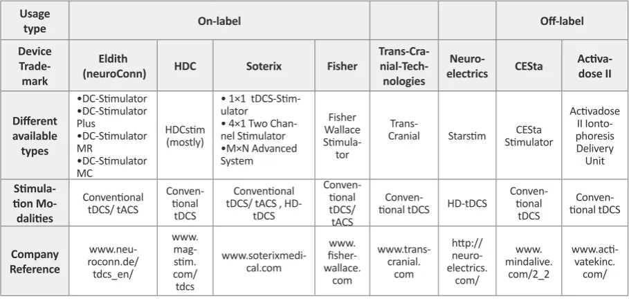
Presently, there are many commercial types of TCS
stimulators which have enabled some clinical and
re-search applications. They can be categorized as off-label and on label devices. The on-label devices are particu -larly designed and then used for TCS and mostly tDCS
due to their applicability for clinical trials, while the
off-labels are used for TCS in addition to some other
appli-cations. In the following categories, there will be a brief description on some of these items, prior to summarizing them in table 2.
The front panel of an ideal TCS device is illustrated
in the following figure to provide a view of its required parts.
On-Label Devices
6-1) Eldith stimulator – direct current (DC) stimula
-tor used in clinical trials, in a hospital setting with the supervision of specialized personnel.
6-2) HDC series – programmable and portable
de-vice for tDCS treatment. The latest in this series is the HDCstim device.
5. TCS Requirements
Prior to start the procedure, the availability of the re
-quired materials should be carefully ensured. In the fol
-lowing, a set of essential materials is mentioned:
• TDCS device; the main component of the stimulation
process comprises an electric apparatus which delivers
the considered power to the target.
• Two sponge electrodes; the outer layer of the inter -face between the involved tissue and the power applying
device.
• Two conductive rubber electrodes; the inner part of the sponge electrodes, supposed to deliver the applied current as a conductive medium.
• NaCl solution; the conductive solution used to obtain a better contact.
• Two rubber head bands; used to fasten and fix the electrodes on subject’s head.
• 9V Battery (2x); the source from which the required power is generated.
• Cables; placed between the device and the electrodes, used to guide the electric power to the electrodes.
• Measurement Tape; used to determine the aimed
place of stimulation and to locate the electrodes in order
to have the desirable montage.
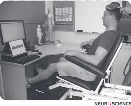
The following picture illustrates the required
compo-nents of a common TCS device.
Usage
type On-label Off-label
Device
Trade-mark
Eldith
(neuroConn) HDC Soterix Fisher
Trans-Cra- nial-Tech-nologies
Neuro-electrics CESta Activa-dose II
Different available types • DC-Stimulator • DC-Stimulator Plus • DC-Stimulator MR • DC-Stimulator MC HDCstim (mostly)
• 1×1 tDCS-Stim -ulator
• 4×1 Two
Chan-nel Stimulator • M×N Advanced System Fisher Wallace Stimula -tor
Trans-Cranial Starstim StimulatorCESta
Activadose II Ionto-phoresis Delivery Unit Stimula-tion Mo-dalities Conventional tDCS/ tACS Conven -tional tDCS Conventional tDCS/ tACS ,
HD-tDCS Conven -tional tDCS/ tACS Conven
-tional tDCS HD-tDCS
Conven -tional tDCS Conven -tional tDCS Company Reference www.neu-roconn.de/ tdcs_en/ www. mag-stim. com/ tdcs www.soterixmedi -cal.com www. fisher -wallace. com www.trans-cranial. com http:// neuro-electrics. com/ www. mindalive. com/2_2 www.acti -vatekinc. com/
6-3) Soterix Medical stimulator: direct current (DC)
generator used specially for delivering the required current to the target of the stimulation in both
conven-tional and high definition type of stimulation.
6-4) Fisher Wallace Stimulator: a portable, safe and
effective way for delivering a gentle, patented electri
-cal current via sponge electrodes.
6-5) Trans-Cranial Stimulator: a portable, safe and
easy-to-use device for delivering direct current to the
scalp.
6-6) Starstim: a noninvasive wireless
tCSneuro-stimulator used to perform electrical stimulation along
with EEG monitoring.
Off-label TCS Devices
6-7) CESta – a high quality cranio-electro stimulation
(CES) device capable of being promoted for use as tDCS, Micro-TENS or as a colloidal making device.
6-8) ActivaDose II Iontophoresis Delivery Unit – a
delivery unit used to administer the prescribed soluble salts or other drugs into the body for medical purposes
as an alternative to hypodermic injection. Figure 2. A sample tDCS device; the “Time Remaining” part
reverse counts the preset time; the “Current” part indicates the applied current intensity; Patient care can be dedicated to manually increase or decrease the intensity and abort the whole process if necessary; the “Impedance Scan” estimates the electrodes contact impedance and verifies its quality to optimize the place of electrodes, it will be optimal if the whole triangle gets colorful; “Duration and Intensity” knobs account for the preliminary stimulation adjustment. When set to the Active mode, Scan (scans and checks the contact’s impedance), Tickle (applies an excess amount of current in cases of insufficient contacts), Pass (enables the main process of stimulation) and Buffer (isolates the device and electrical fields from environmental inputs –e.g. MRI ) options should be adjusted, otherwise Sham mode should be selected; AC or DC types can be selected with the pertaining switch.
Eldith Stimulator
There is a variety of options in this category based on
the DC/AC stimulation type, single/multi-channel de
-vice, clinical/personal at home use, etc. It should be noted that the basis of the design remains the same, although some physical and practical aspects of the device vary.
6-1-1) DC-Stimulator for tDCS
Supplied with a microprocessor-controlled constant
current source, it serves two main modes of stimulation, including single (with a continuous stimulation, configu
-rable fade-in and fade-out) and pulse one (cyclic turn
-ing on/off for the stimulation with a configurable pulse width and interval).
6-1-2) DC-Stimulator Plus for tDCS and tACS
Presenting two stimulation types of DC (unipolar) and AC (bipolar) in different modes of active and sham stimulation, four stimulation modes have been provided; ‘’tDCS’’(continuous stimulation, adjustable current of 0 to ± 4,500 uA ,duration 15-1,800 s , duration of fade-in/ fade-out 1-120 s) , ‘’Pulse’’ (cyclic turning on/off of stimulation, duration of complete pulse cycle/interstim
-ulus interval (ISI) 300-2,000 ms, pulse width 200-(ISI-100), number of pulse cycles 1-500), ‘’Sinus’’( bipolar sinus waves adjustable current of 0 up to 3,000 uA , offset 0-±1,000 uA, frequencies of 0-250 Hz, adjustable phase 0-360 degree, duration 0-480 min), ‘’noise’’(normally distributed broadband low and high frequency noise, ad
-justable current of up to 1,500 uA, offset 0-±1,000 uA, duration 0-1,800 s, fade-in/fade-out period of 0-120 s)
6-1-3) DC-Stimulator MR
Equipped with the same facilities of the previous mod
-els, an extra amenity of MRI compatibility has been added, since no interference of the fMRI images during EPI sequence had been observed.
6-1-4) DC-Stimulator MC
7-Equipped with 4 programmable,
microprocessor-controlled constant current sources using independent
channels, it can serve various stimulation types includ
-ing tDCS, tACS, CES17, GVS 18 and tRNS19 . This device
is provided with the aforementioned modes of
stimula-tion, including continuous, cyclical switching on and off, sinusoidal stimulation and their combination. The device is also fMRI compatible and neither makes nor takes any interference.
HDC Stimulators – HDCstim
This device has not only been provided with the
pre-vious models’ facilities, but also equipped with some
other accessories in order to monitor the impedance of
the contacts, to alarm in the case of insufficient contact. Generally, it has the ability to deliver DC stimulation to the target tissue, as well as the others.
Soterix Medical Stimulator
Offering a variety of devices, the overall idea of the
design mostly remains the same as using a current
gen-erator. Unlike the others, it is equipped with the high definition type and benefits from some excess modes to technically simplify the whole process, such as monitor
-ing the contact efficiency of the electrodes.
6-3-1) 1×1 tDCS Low-Intensity Stimulator
The Soterix Medical 1*1 line of low-intensity tDCS
stimulator is mainly designed to produce low levels of
DC current running through the two electrodes, the an
-ode and the cath-ode placed on the target. It has several
features to improve the safety of the process and to
pro-mote the subject comfort. These include, TRUE CUR
-RENT, SMARTscan, RELAX and Pre-Stim TICKLE. In the SMARTscan mode, a continuous visual illustration of the electrodes’ quality is provided, before the stimula
-tion or during it. In TRUE CURRENT mode, the sup
-plied current is clearly depicted. In the TICKLE mode, a
very weak current prior to tDCS may be applied in order
to condition the skin. The RELAX mode also allows the
clinician to reduce the current less than its preset given
some exceptions such as the subject feedback. This in
-cludes two types of devices, the simple one and the ‘clin -ical trials’type which can be used to more conveniently
perform many clinical investigations.
6-3-2) 4×1-C2 Multi Channel Stimulation Interface
Being an accessory to the isolated 2-channel
stimula-tor, it is designed to be used with 5 leads where 4 leads (colored) are connected to an output of the stimulator,
and the remaining lead (white) is connected to the other output of the tDCS stimulator. This setup benefits from up to four modes including scanning, pass, tickle and buffer. In the first mode, the impedance between the surface of the electrode and the skin is scanned to find
the optimized place of contact leading to a better current
division among the electrodes.
In the second mode, the current will be delivered to the surface of the scalp and in the third mode, a small
current will be applied through a selected electrode to
lower its impedance if necessary. In the buffer mode, the
electrodes will be isolated from the main circuitry of the
apparatus, enabling the device compatibility with MRI and TMS.
6-3-3) M×N Advanced Neuromodulation Systems
As a non-invasive neuromodulation platform
devel-oped in M×N HD-tDCS stimulators (8-channel and 4-channel), this setup provides the clinician with control of electrode placement and the current, resulting in a novel noninvasive targeting. As such, the HD-targets and
HD-explore systems enable the investigators to carry
out automatic or manual dose optimization. The MXN system can be configured for effective DC stimulation without reportable sensation in most subjects. This sys -tem consists of multiple electrodes arranged in a special
montage (4×1 for instance), resulting in more focal cur
-rent delivery to the cortex.
Fisher Wallace Stimulator
This device is specifically equipped with an AC deliv
-ering source which can supply 0-4 mA output current. It has been designed to work on patented frequencies of 15/500/15000 Hz with the pulse width of 33 microsec
-onds, where the maximum charge per pulse will be 0.13 micro coulombs. The setup has also been provided with On/Off Time Per Burst of 50 milliseconds and 16.7 mil
-liseconds, respectively. Its configuration can be simply changed to tDCS application for investigational studies. It is mainly based on conventional tDCS model having
saline soaked sponge pads and its current density can be altered using a knob which can both be used to
deter-mine the current intensity or turn the device on/off.
Trans-Cranial-Technologies
This device can provide a direct current of 0.5 to 2 mA in 0.1mA increments; it can be used for up to 30 min
-utes with countdown current display. Meanwhile, it can monitor and display actual current and electrode quality;
it also ramps up in a slow manner to raise the subject’s
comfort through conditioning the skin. Moreover, auto -matic abort has been added in cases of excessive
resis-tance to prevent skin irritation.
Starstim
Multi-channel programmable tCS is capable of
per-forming current-controlled tDCS, tACS and tRNS in sham or user-defined waveforms. It can stimulate and
record at the same time using the same electrodes which
provides the user with a visualized EEG monitoring. It is equipped with EEG data output and Bluetooth 2.1 com
-munication set, while is compatible with different oper
-ating systems of Windows and MAC. Finally, it can pro -vide a maximum current of ±2 mA per electrode while
recording EEG signals at a specific sampling rate.
CESta Stimulators
Analogous to the prior models, it is equipped with the
essential accessories to deliver DC current to the aimed
tissue. It has the ability to check the connections to es
-timate the skin impedance in order to find the possible deficiencies in the electrodes’ contact. It is also provided with some presumed function libraries, prepared in some tables, to determine the required specifications of stimu
-lation according to the patient’s disorder.
Adding to the above specifications and function, Mi
-cro-TENS stimulation, tDCS, Colloidal Silver produc -tion and Synchroniza-tion with the company’s Digital
Audio-Visual Integration Device (DAVID) and other types of Portable and Lightweight (PAL, PAL36)devices can be considered as CESta stimulator’s functions.
ActivaDose II Iontophoresis Delivery Unit
The ActivaDose II Iontophoresis Delivery Unit is in -dicated for the administration of soluble salts or other drugs into the body for medical purposes as an alterna-tive to hypodermic injection in situations when it is ad-visable to avoid the pain of needle insertion and drug
injection and to minimize the infiltration of carrier fluids,
or to avoid the damage caused by the needle insertion
when tissue is traumatized.
It only works at a continuous stimulation mode and is
able to provide the required current up to 4 mA in a ramp
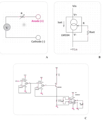
7. Circuitry and Schematics
The key feature in designing a TCS device is the use of
an adjustable current regulator, which contains different parts of electronic components. A simple tDCS device can be assumed as a current source. Voltage and cur
-rent regulators, LM334 and LM317 for instance, which
usually provide an output of constant voltage or current
respectively, regardless of the changes in other charac -teristics of the circuit including input voltage current or load conditions are used to supply the required output
current for the stimulation process. There are two main implementation techniques: linear and switching each of which has some advantages and disadvantages. Simpler
design and lower cost are the most important advantages
of the linear current regulator, in contrast to switching
types which have complicated design and more
elec-tronic parts. A favorable efficiency and low weight of
switching regulators are the key advantageous factors
for such a portable device. A linear regulator employs an active (BJT or MOSFET) pass device (series or shunt) controlled by a high gain differential amplifier whereas
a switching regulator converts the DC input voltage to a
switched voltage applied to a power MOSFET or BJT switch.
Common switching regulators mainly include Buck
(step-down), Boost (step-up), Buck/Boost (step-down/ step-down). Moreover, the TCS apparatus usually re -tains the advantage of boost topology in which the
volt-A B
C
age will rise until it reaches the final threshold to supply the aimed current.
Linear regulators generally include integrated current
source (LM334) and Operational amplifiers.
Another common fashion of generating current is us-ing voltage to current converters which is used by some
commercially available devices. In this method, an input voltage will be modified in order to transform into the adjusted current.
8.
Conventional vs. High Definition TCS
There are mainly two separate types of transcranial current stimulation techniques including conventional
and High-definition TCS. Conventional transcranial di
-rect current stimulation (tDCS) supplies weak di-rect cur
-rents (260 mA-2 mA) applied to the scalp via rectangu
-lar sponge patches (nominally 25-35 cm2) covered with conductive gel(F. Hummel et al., 2005; Iyer et al., 2005; Marshall, Molle, Siebner, & Born, 2005; Nitsche & Pau
-lus, 2000). Once conventional type had been invented and used to perform studies to investigate the efficacy of TCS, it showed to suffer from poor spatial precision
as it involves a broad region of cortex owing to skull
dispersion. A newer design called high definition tDCS (HD-tDCS) provides a focal current delivery to discrete regions of cortex and to avoid diffuse spatial resolution. In this approach, multiple (more than two) smaller gel electrodes, instead of using two large pads, are used to target specific cortical structures. The HD-tDCS can be performed via different montages. One of the possible electrodes configurations is the 4×1 HD-tDCS montage in which 4 electrodes are placed around a central one; thus, a set of 5 electrodes is used to deliver the required current to the cortex, which results in higher focality as compared to the conventional type (Caparelli-Daquer E et al., 2012). Both types tend to modulate the brain activ -ity to cause a decrease or an increase in pain and sen-sory experience as well as offering some other possible
effects(Borckardt et al.).
9. Alternating vs. Direct Current Stimulation
Since more than a decade ago, abundant studies with
various designs have been carried out to investigate the
possible effects the low-intensity (sub-threshold) current stimulation on cortical excitability, but great proportion
of it has been dedicated to direct rather than alternating
current stimulation. In fact, the only difference they have is regarding their current type, which is simply alternat -ing in tACS and direct in tDCS while the required
ap-paratus and other accessories remain the same. The two
ways often cause different effects in brain and its
func-tions, the main objective of the performed studies.
The recent studies performed in the previous decade
(2000s to 2010s) reveal the tDCS efficacy through vari
-ous achievements including, significant effects on visual recognition memory task in Alzheimer disease (Boggio et al., 2009),decreasing tics in two patients with Tourette syndrome(Mrakic-Sposta et al., 2008), decrease in crav
-ing for alcohol (Boggio, Sultani, et al., 2008) , significant
-ly reduced craving for some foods (Fregni et al., 2008),
reduction in subjects’ propensity to punish unfair
behav-ior (Knoch et al., 2008), increased recognition memory (Ferrucci et al., 2008), significantly reduced depression scores (Boggio, Rigonatti, et al., 2008; Fregni, Boggio, Nitsche, et al., 2006),increased sleep efficiency and de
-creased arousals(Roizenblatt et al., 2007), de-creased re
-action time (Boggio et al., 2006) and improvements of motor functions (Fregni, Boggio, Santos, et al., 2006) in Parkinson’s Disease and decreases in Epilepsy seizure frequency (Fregni, Thome-Souza, et al., 2006), improve
-ment in accuracy of the picture naming task (Monti et al., 2008), decreased reaction time (F. C. Hummel et al., 2006) and significant motor improvement(Boggio et al., 2007; Hesse et al., 2007) have been the outstanding at -tempts in Stroke patients’ clinical trials in addition to the
novel opportunities in the future perspective.
Over the recent decades, some alternating current
stimulation clinical trials have investigated the visual
phosphene induction in healthy subjects (Kanai, Chaieb, Antal, Walsh, & Paulus, 2008), the improvement in im
-plicit motor learning task in healthy subjects (Chaieb, Antal, Terney, & Paulus) and assessed this technique’s
effects on patients suffering from generalized anxiety
disorder (Roy-Byrne et al.). Additionally, this approach has succeeded to lead to a significant difference in the average pain intensity in spinal cord injury patients (Tan et al., 2006),(Capel, Dorrell, Spencer, & Davis, 2003), significant difference in beta-endorphin levels (Gabis, Shklar, & Geva, 2003), EEG alterations in alpha and beta band frequencies (Schroeder & Barr, 2001) and fi
-nally, improvements in attention (Southworth, 1999).
10. TCS Electrodes
One of the noteworthy aspects of a TCS study is indeed the possible electrode-gel parameters according to their
main characteristics including size, shape and materials for the electrodes, and also the required chemical com
11. TCS Montages
A tCS montage is a protocol determining the state of the
stimulator device either in active or sham mode. Among protocol’s parameters, the most important is the elec -trode positioning which depends on the goal and design
of the study. Typically, there are two types of position
-ing, bilateral and unilateral. Unlike the bilateral position
-ing in which both electrodes are placed on scalp,in uni
-lateral, only the active electrode is placed on the scalp
and the reference is placed mostly on supraorbital area or
shoulder, contralateral to the active electrode (generally,
in unilateral design the reference electrode can be placed
anywhere except the scalp). In other words, bilateral It should be noted that, these parameters are mainly for
HD-tDCS type and the electrodes of the conventional
type are completely different, as they are simple sponge pads containing rubber electrodes (figure 4) and soaked in a saline solution (NaCl 0.9%)(Ben Taib & Manto, 2009).
Figure 4. Sponge Pads (left) containing rubber electrodes (right)
Various pad shapes and sizes have been tested to rebut the common opinion of a considerable difference in
elec-trical stimulation’s tolerance ((Forrester BJ, Petrofsky JS., 2004). Moreover, the application of NaCl solutions in the range of 15 to 140 mM to sponge electrodes is
proven to possibly cause no pain to the subject and to be
perceived as comfortable during the tDCS trial (Dundas, Thickbroom, & Mastaglia, 2007).
In fact, all these efforts are made to achieve the appro -priate solid-conductor and to partly guarantee the most
desirable electrode durability, skin safety and subjec
-tive pain. There have been some experiments related to
HD-tDCS to discover the most appropriate electrodes
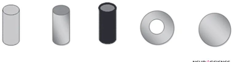
for stimulation, as items have recently been examined in well-designed investigations.
A collection of five types of solid-conductor (figure 5) (Ag pellet, Ag/AgCl pellet, rubber pellet, Ag/AgCl ring and Ag/AgCl disc) and seven conductive gels (Signa, Spectra, Tensive, Redux, BioGel, Lectron and CCNY-4) were identified and examined. Finally, the Ag/AgCl ring
in combination with CCNy-4 gel resulted in the most
fa-vorable outcomes.
Under anode stimulation, electrode potential and tem -perature rises generally occurred in all electrode-gel combinations except for both Ag and rubber pellet
elec-trodes with Signa and CCNY-4 gels. Sensation results however, are shown to be independent of stimulation polarity (whether to use anode or cathode).
Ag/AgCl ring electrodes were found to be the most
comfortable followed by Ag, rubber and Ag/AgCl pellet electrodes across all gels(Minhas, et al.).
stimulation can be performed with the two electrodes
(anode and cathode) on analogous regions of the right
and left hemisphere while the unilateral montage
com-prises positioning the active electrode on the DLPFC and the cathode on the contralateral supraorbital.
Of note, Nitsche et al., have provided an overview of
the recent studies introducing different aspects of their
protocols as well as details on their montage (Nitsche et al., 2008). Placing the stimulation electrode on M1 or
hand area and the reference electrode on the contralateral orbit alters the brain activity of the subjects depending
on the polarity of stimulation. As noted, with cathode be
-ing the active electrode, the excitability of the involved area reduces, while anodal excitability enhances after
the anodal stimulation in basic neurophysiology
appli-cations. Moreover, this montage can enhance β-band in motor cortical excitability after the anodal stimulation while it is reduced after the cathodal one using the
intra-muscular coherence analysis (Power et al., 2006). While using anode as the active electrode, placing the stimula
-tion electrode on S1 and the reference on contralateral
orbit is shown to result in laser-evoked pain perception diminution in cathode stimulation and improve the
spa-tial acuity. Active electrode on Oz and the reference on
Cz results in visual perception threshold elevation
us-ing the cathodal stimulation (Antal, Nitsche, &Paulus, 2001) and reduction in phosphine threshold by anodal stimulation (Antal, Kincses, Nitsche, & Paulus, 2003).
When placing anode on Cp5 and the reference electrode on the contralateral orbit, the stimulation leads to an en
-hancement in language learning (Floel, Rosser, Michka, Knecht, & Breitenstein, 2008).
Studies with unilateral vs. bilateral electrode position -ing have reemphasized theimportance of the reference
electrode’s position in later analyses. The positioning of electrodes is normally based on the 10-20 international EEG system which is represented in figure 6.
12. Safety Concerns
Currently, the required current for stimulation is 1 to 2
mA at maximum and the clinical devices usually guar-antee not to exceed this level to let the procedure remain
innocuous for the patients. When applying a 1 mA direct current via two electrodes of 7×5 cm in size, the amount
of the electrical current will predict an axial and
tangen-tial cortical current density of approximately 0.093 A/m2 and 0.090 A/m2, respectively, (Zaghi, Acar, Hultgren, Boggio, & Fregni).
Despite a common concern assuming the process
prob-ably dangerous, it generally does not cause considerable adverse effects, although it has some, including de -creased heat and cold sensory thresholds and a marginal analgesic effect for cold pain thresholds when using
HD-tDCS technique. No meaningful effects on mechanical
pain thresholds and heat pain thresholds are usually
observed(Borckardt, et al.). In the conventional type, a
group of healthy subjects and patients were examined to determine what kind of TCS-related problems they may
report. The most common reported adverse effect turned out to be the tingling sensation. In addition, the light
itching sensation under the stimulating electrodes was
considered as an undesirable effect. However, after the stimulation, infrequent headache, nausea and insomnia were rated as negative effects. The former sets of effects had mainly influenced the healthy group, while the lat
-ter were mostly reported by the patients(Poreisz, Boros, Antal, & Paulus, 2007).
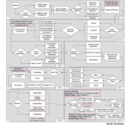
13. Methodological Design for TCS Studies
Typically the design of a study TCS-involved is a straightforward procedure in which the main target is generating reliable and valid data in order to measure
the effects of TCS in a certain neurocognitive function. There are some critical questions (Figure 7) which must
be answered in order to create a study design based on an
a priori hypothesis and the main question. We have cre
-ated a diagram based on these critical questions (CQ) to
show the roadmap of a complete methodological design
of such a study (Figures 7 to 9).
13.1. The Roadmap
A normal study-design consists of six major steps (Fig
-ure 8), which would be based on the hypothesis and the main goals of the study. The first step is the answer to the critical questions 1 to 3. Generally, there are two main types of studies: studies with single (e.g. Normal People) or multiple target populations (e.g. Normal Con
-trols and Alzheimer’s Patients). Normally, if the purpose
of a study is to investigate the effects of TCS in different
conditions (for instance the hypothesis that TCS exerts
positive effects on working memory performance in
nor-mal people), single-target is the method of choice. On the other hand, when the purpose is to determine dif -ferences of TCS procedure effects in different targets
(for example, the hypothesis that TCS increases work -Figure 7. The critical questions which need to be answered to generate a roadmap
ing memory performance in Alzheimer’s patients with
better efficacy compared to normal subjects), the sec
-ond method (two target populations) should be applied. Whether we choose single-target or multiple-targets, the rest of the roadmap is mostly the same; however, in order
to generate appropriate comparable data in a
multiple-target design, we must divide it into the same number of
separate single-target designs and compare their data to
make the final decision of the experiment. This division brings on the sample matching concern, which means all the samples should be two by two matched.
After specifying the target populations we have to de-cide on the neurocognitive function of interest and its
assessment method. Behavioral methods (e.g. Question
-naires) and brain mapping techniques (e.g. EEG) are two types of assessments could be used alongside TCS. The
last process of this step is determining the region of
in-terest (ROI) on the brain. Most of the time results from previous TCS or TMS studies are used to find the appro
-priate region to intervene.
13.2. Intervention Types
The second step is to choose the intervention types to
use in the study, which is directly related to the critical questions 4 through 6. This step is divided into three in
-ner steps illustrated in the second box of Figure 8. “Ac
-tive” and “Control” are the two categories of intervention typeswhich their specification should be fixed in the first (CQ 4, 5) and second (CQ 6) inner steps, respectively.
In the first inner step we have to specify the active in
-terventions from two available choices; anodal and cath
-odal, and after that to determine the place of reference electrode based on the “Electrode Montage” in which
we should choose montage of electrodes placement from
three types of montages: 1: Double Monopolar Montage in which two active electrodes (contralateral to each oth
-er) would be placed on the scalp and one reference elec
-trode outside the scalp. 2: Monopolar Montage which is the same as the first type with only one active electrode on the scalp. 3: Bipolar Montage in which both active and reference electrodes would be placed on the scalp.
The second inner step is to decide on the control
inter-ventions. There are two types of control interventions: “Active Control” and “Sham Control”. Active control refers to an intervention different from (but with re
-gard to) the active intervention, which divides into three types: different stimulation of the same region (e.g. if the active intervention is anodal over F3, a possible active control could be cathodal over F3); same stimulation of
the contralateral region (e.g. if active intervention is an
-odal over F3, a possible active control could be an-odal over F4); same stimulation of another region (e.g. anodal over F3 for active and anodal over O4 for control).
Considering all types of the available active and control
interventions, combinations of a variety of them seems possible however, only one of these combinations (per
-mutations) would be used in a study, which suggests that
we must choose this combination carefully and make a
decision based on our hypothesis, goal and previously published articles. After specifying the “combination of interventions”, we then have to decide on the electrodes location according to brain regions. We should find their
exact position based on landmarks or an international
standard in order to be comparable with other studies. MRI-guided measures and international the 10-20 stan -dard for electrode positioning are the two systems which
are widely used in intervention studies. Final part is about specifying the size of each electrode. Normally, 5 x 5 or 5 x 7 cm2 electrodes are used.
13.3. Session Design
Session Design is the third step in the process of
design-ing a TCS study. In this step, the procedure of each ses -sion and the experimental protocols of the study should be designed to give answer to the seventh critical
ques-tion. At first, the target TCS effect should be determined
which is the outcome of our decision on incorporating
offline, online or mix of both protocols.
In an online protocol, the assessment procedure is per
-formed during the intervention, which requires counter
-balanced (across subjects) sessions with respect to the
intervention types in order to generate enough data for measuring the effects of intervention during a certain
cognitive process. In contrast, the assessment task in the offline type is performed either post to intervention or in
a pre-post procedure meaning that it would be performed
both before and after the intervention. The combination of offline and online designs is another possibility which
is a good candidate for an advanced procedure design as we can measure the effects of both the stimulation and
assessment tasks at the same time. Mostly, in this type of design, online stimulation is conducted immediately after offline one or vice versa (e.g. ten minutes of offline stim
-ulation followed by ten minutes of online stim-ulation).
13.4. Stimulation Protocol
In this step (Forth step), the technical settings of stimu