Copyright © 2012 IJECCE, All right reserved
Foundational Block Modeling Structures for Computer
Systems Representation
Anthony Spiteri Staines
Abstract — This work explores and explains the use of basic block modeling structures, their function for representing computer systems and computer systems structures. The main use of block diagrams and notations is to represent system configurations. Traditionally this has been done using different notations and structures. One of the major problems is precisely that there exist a myriad of ways how to do this. This work challenges the traditional approaches by using a particular method for connecting systems, sub-systems and components together. An exhaustive identification of possible configurations is given. The structures described here are represented both graphically and formally. This approach supports formal representation and description of systems. A reduced form of the system structures can be developed. Various examples and a practical case study are explained along with results, observations and a conclusion.
Keywords — Block Diagrams, Formal Methods, System Composition, System Modeling, Visualization
I. I
NTRODUCTIONThe past decades have demonstrated the creation of many new notations and representations for different computer and hardware systems. The concept of information systems is represented within systems theory and development methods normally derived from the area of requirements engineering.
This paper attempts to question and identify a semi-formalized approach for systems representation. By no means does it try to claim that the suggested approach presented is the best or pinpoint at a definitive solution.
There are numerous ways for representing systems; there are some basic, fundamental approaches that have validity now and in the future [6]-[10]. This is because even though there are radical developments, the basic, elementary processing and ways of conceptualizing systems remain unchanged. These can be called basic building blocks or elementary structures.
When ‘theorizing’ about systems we are not really concerned with the type or nature of the system. We are concerned more about the relationships between the basic elements or units of the system and how to describe these relationships both formally and informally.
If one has to consider the reasoning behind systems, conceptually the system is to be viewed as an abstract set of components or sub systems. i.e. an aggregation of sub systems, objects, entities or units that are interacting.
Analogies between certain types of systems and their structures exist. These analogies can be used to theorize about system concepts.
Computer Systems are a special type of entity that can
have different types of behavior requirements. But here the focus is rather on top-level discrete, deterministic behavior and ordering of relationships between the system, sub-system and its components.
Various notations and structures have been used to describe systems and their structures, it is impossible to pinpoint or find just one representation that is suited to all needs. This is because of the diversity in the system being modeled.
This work focuses more on the computer systems analysis relationship. Because this is a general view that encompasses, i) synthesis, ii) environmental control, iii) optimization layout, iv) environmental adaptation, v) reliability in terms of configuration and number of modules, vi) stability or decidability in relation to specific constraints.
It is impossible to touch upon all the issues related to systems such as compatibility and probability. The work of this paper is confined to the elementary modeling aspects of a system from the compositional point of view. Its units and links remain valid for future reference. This is observed from all the literature that strives to represent structures in various forms and almost always use block diagrammatic concepts for their foundations.
II. B
ACKGROUNDWhen considering system configurations the use of block diagrams and notations is essential as evidenced in [1]-[10]. This is also evident from the analysis and design methods that have been used for the past three decades at least. The traditional methods and methodologies used for structured and unstructured analysis and design are heavily characterized by the use of block models in their various forms. In certain occasions the graphical representation of a system can be done also using something like a specification language or a set of specific symbols, labels and quantifiers.
Copyright © 2012 IJECCE, All right reserved
III. P
ROBLEMD
EFINITIONThe issues behind system characterization, e.g. how to represent, inputs and output relationships and connectivity to sub components have been and are a major research area. Additionally the following problems can be identified. i) System Complexity: This considers how many interrelationships should there possibly be for a system to be properly understood. Also there is the classic dilemma of concise vs complex representation. This means that what is suitable for one occasion is not proper for others. The characteristics of a good system in terms of the visual representational layout have to be understood. ii) Visual and Formal representation: This is how should the system be specified both visually and formally i.e. mathematically from a specification viewpoint. Many notations are based on a one sided view only. For proper specification the system representation should be possible both visually and formally. This could allow the proper comprehension of behavior and structural complexity. iii) Decomposition: It should be possible to decompose a system further. Even abstracting or hiding complexity issues or unnecessary detail is required. This implies that unimportant information for high level representation should be removed or condensed. iv) Behavior: Behavior relates to expression of different types of configuration and behavior of individual components. E.g. synch, parallel, etc.
IV. F
OUNDATIONB
LOCKM
ODELINGS
OLUTIONThe proposed solution considers the use of block structures for system modeling and presents a formal way of representation. The approach considers a system as a set of subsystems or components from a high level of perception. The following issues are addressed. i) proper labeling of components and ii) further labeling of subgroups, iii) relative positioning, iv) association and relationships with each other, v) association and relationship labeling vi) different types of correspondencies. Nodes in the graphical notation serve to represent the components and communication channel for joining components. The edges serve to connect the components via a communication channel respectively.
V. S
YSTEMC
OMPOSITIONALS
TRUCTURESA. System Composition
A complete system is defined as a set of individual units or sub systems that communicate with one another. Communication and events have to initiate in a sub system or unit. The complete system is defined as a set of subsystems, connection channels, and connectivity arcs. The complete system in fig.1 is defined as a three tuple (S,F,C) network model that is decomposable. Where S = finite set of subsystems,S = {s1,s2….sn},S, F= Set of
directed flows/arcs from a subsystem s to a channel c or from a channel c to a subsystem s; F
CxS
SxC
;
F ;C= finite set of channels ,C ={c1,c2,…cn} ,
C , S,F,C are mutually disjoint.
;
)
(
)
(
:
s
S
I
s
O
s
i.e. no connector arc is input and output for the same processor.; ) ( ) ( :
c C I c Oc i.e. no connector arc is input and output for the same channel.
(sS(I(s)O(s)))(CC(I(c)O(c)))= connection name , i.e. dangling arcs are not permitted.
(out(s,f(s))
in(c,f(c)))
(out(c,f(c))
in(s,f(s)))
; the output of a component, i.e. the output arc connects to a channel. I.e. it is the input arc for the channel. From the channel the output arc connects to another component. It is not possible to have channels that are not connected. The configuration of the computer system is composed of different possible paths or system routes. These semantics are defined in terms of sets or ordered sting expressions. I.e. any configuration can be expressed in a fully distributed form. More compact forms of expression are possible.B.
Sequential Composition
Sequential composition is when the system components are connected sequentially or in series. The most simple form of sequential composition would be a sequential connection between two systems. This is shown in fig. 1.
S1a!c1a?S2
comp1= S1a!c1a?S2 comp2= S2b!c2b?S3
If the basic system composition has a single part then the system can be written as System = Comp1. If basic system composition is defined as having two parts comp1 and comp2 this system can be written as System= Comp1;Comp2. The basic sequential composition for two systems, three systems, etc. can be easily done.
C. Repetitive Compound Sequential Composition
If the sequential pattern presented is extended the result is that a repeated sequential composition is possible. This would be denoted or summarized by the equation (1) given below where n = (total number of systems or components -1), n>i and n>1. This is illustrated in fig. 2 where n=3.
Sequential System S =
n i i i i i
iO C I S
S
1
1;
?
! (1)
D. Parallel Composition
A simple operand for representing parallel composition is ||. E.g. if we have A||B this implies that A and B are parallel compositions. Usually this would imply having three system components. Either one input component and two output types as indicated in fig. 3 or two or more input components and a single output component as in fig. 4.
Parallel system composition having multiple occurrences of the same type can be denoted using the
i
sinotation for short. This is shown below.Copyright © 2012 IJECCE, All right reserved Parallel System S = 1
!
1;
1
i i i i ni
S
O
C
I
S
(2)ii) Many system components output to one system component (3). This can also be a form of joined or synchronized behavior depending in what order the messages are passed.
Parallel System S = 1
!
1;
1
S
iO
iC
iI
iS
ni
(3)Fig.1. Sequential composition
Fig.2.
Repetitive
sequential compositionFig.3. Parallel composition
Fig.4. Joined repetitive parallel composition
Fig.5. Bi-directional composition
Fig.6. a) Choice-composition
Fig.6. b) Alternative choice-composition
Fig.7. Complex parallel composition
Copyright © 2012 IJECCE, All right reserved
E. Complex Parallel Composition
Complex parallel composition is indicated when a system branches into parallel sub-systems and the parallel sub-systems connect to other systems and possibly branch out into other parallel sub-systems. Thus complex parallel composition is just normal parallel composition having more complexity. Fig. 7 is an example of this.
The actual parallel composition does not explain the actual temporal ordering of message or communication sequences. A form of parallel configuration could thus be considered as a synchronized join. This can be expressed as follows:
comp1= S1O!c1I1?S3
comp2= S2O!c2I2?S3
(comp1||comp2)
F. Bi-Directional Composition
Bi-directional composition can signify many different scenarios. In this context it is taken to imply that the actual communication of two or more components has no special ordering. The ordering is undefined. It can be either parallel or sequential. Different possibilities will exist. This is shown in fig. 5
comp1= S1a!c1a?S2
comp2= S2b!c2b?S1
Comp1 and Comp2 can be represented or denoted as x,y respectively. It is possible to have two sequences x;y or y;x. Depending on how the system works the configuration could imply parallelism. The ordering of the composition could be taken to be undefined. If it is defined then the system composition can be taken to be a simple sequential one.
To show the possible alternative configuration the ¦ operand is specified for use. This operand or operator denotes choice or possible selection between alternatives. I.e. it is like or-logic. E.g. for the example in fig. 5 the concise proper representation is (x;y¦y;x).
G.
Choice Composition
If the concept of choice between two sub-systems or components is really necessary to express, different ways of communication, a specific way for expressing this can be found. In this work, choice can be presented either as multiple single path or direction from a component to another. It could be included at the channel level for special cases.
The diagrams in fig. 6a and 6b represent different configurations for indicating choice logic. Note that the different configurations will result in different labeling and their representations will differ.
Using short notation the system in fig. 6a is composed of A, B and C respectively. This system can be represented as A;(B¦C) or A;(C¦B). Other forms are (A;B ¦ A;C) = A;(B¦C). Further forms of expressing these concepts can be indicated. E.g. it could also be expressed in terms of computer programming pseudocode. E.g. If A Then B Else C Fi.
H.
Loops
Usually for system composition at a high level the inclusion of looping behavior might not be significant. Loops can be considered as a special case of behavior.
The most elementary type of loop can occur when a system component connects back to itself. Repetitive or self system feedback can also be called recursive. Recursion here implies that the system component sends or is configured to connect to itself. See fig. 8.
comp1= S1a!c1a?S1
If several similar recursive connections exist, these can be denoted in a concise format.
To define a loop we can write REPEAT or LOOP expression before the system composition to indicate that there is a loop. If there is a special condition to terminate the loop this could also be included. In normal conditions the branching and bi-directionality could also represent looping.
VI. F
INDINGP
ROPERC
OMPOSITIONALS
EQUENCESConsider the diagram in fig.7, this could also be modified to represent choice instead of parallel composition. Actually, to represent parallel composition this would be straightforward. E.g. ((A;D)||(D;E)||(C;F)). On the other hand consider that the system communication does not happen axiomatically in parallel, then the question is how to find proper sequencing. In this case it is possible to generate a set of string expressions for the configuration. The choice is denoted as a set of strings of alphabet of possible system sequences.
This would be of the general form (A|B|C) = (A|C|B) = (B|C|A)= (B|A|C)= (C|A|B)= (C|B|A). These are the set of possible sequences that could exist. Semantics of the system expression are defined in terms of set of strings that denote the possible system sequencing. The choice operator can be defined in terms of the union of sets of strings generated by the different system configuration. There is no special temporal ordering requirement for such a system.
Similar reasoning can be used for parallelism. E.g. if we have ((A;D)||(B;E)||(C;F)) this implies that different possible sequences could exist. Obviously the parallel composition is commutative as ((A;D)||(B;E)||(C;F)) = ((C;F)|| (B;E)||(A;B))
Certain forms of composition, e.g. a sequence is denoted as a well ordered set that can be represented by letters. A sequence with choice e.g. ((B;A)|(A;B));C = (B;A;C)|(A;B;C).
It can be shown that the operands used like || or | are idempotent, commutative and associative when used with certain expressions, denoting system configuration.
VII. C
OMPLEXC
OMPOSITIONS ANDR
EDUCTIONCopyright © 2012 IJECCE, All right reserved block modeling diagrams reduction is a must. The idea for
reduction would be to regroup sub-systems or components and represent a group of sub-systems as a single system. This is the very opposite of decomposition and can be considered to be a bottom-up approach.
Fig.9 illustrates a complex system composed of 12 sub-systems or components that again have complex relationships between each other. Fig. 10 shows the reduction method applied by grouping. I.e. the result would be to show the system by just having 4 components instead of 12.
Fig.9. Complex system composition
Fig.10. Complex system reduction by grouping
VIII. C
ASES
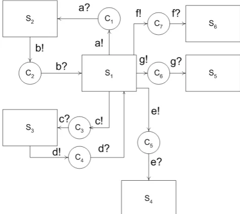
TUDYA simple cruise control system is taken to illustrate the use of the foundational block modeling structures presented. The cruise control system is initially represented as a block diagram consisting of six main components or modules [2]. These are the i) input speed, ii) compute speed , iii) servo adjustment 1 iv) servo adjustment 2, v) display and vi) tyre pressure. The main module is the compute speed. The compute speed module receives and sends signals to the other modules. This is indicated in the diagram in fig. 11.
It is assumed that the system is capable of processing and computing messages in parallel for reception, sending or execution is very fast. This could be parallel
computation. For true concurrent or parallel processing more than one processor and special hardware is required. The actual physical parallel implementation is ignored when the foundational block modeling structures are used. If the system is not parallel, the representation could definitely be simplified.
The diagram in fig.12 shows the full representation for the system using foundational block structures. In addition the system can be denoted using the following sets: ((S2b!c2b?s;S1a!c1a?S2) ¦ (S1a!c1a?s2;S2b!c2b?S1)) || ((S3d!c4d?S1;S1c!c4c?S3)¦(S1c!c4c?S3; S3d!c4d?S1))|| (S1e!c5e?S4)||(S1g!c6g?S5)||(S1f!c7f?S6).
Fig. 12 shows how the system can be simplified or reduced into smaller components. The new composition can be given as follows: ((S1a!c1a?Sr1;Sr1b!c2b?S1) ¦(Sr1b!c2b?S1;S1a!c1a?Sr1)) || (S1f!c7f?Sr2).
Fig.11. Simple cruise control system components
Fig.12. Cruise control system representation
IX. R
ESULTS ANDO
BSERVATIONSCopyright © 2012 IJECCE, All right reserved The concepts presented can be applied to different
notations like composite structured diagrams. Fundamental modeling concepts FMC [5] can benefit from this approach. If component diagrams, system block diagrams, etc. are used for real time systems analysis the fundamental block modeling concepts can greatly enhance these notations.
Highly coupled components imply that there is a great deal of dependency between them. In loosely coupled structures there are some dependencies but the interconnections are weak. Uncoupled components have no interconnections.
Dependency relates to the degree of control one component or system exerts on another entity. It also refers to the degree of complexity of interrelated components. To reduce system complexity unnecessary dependency and unnecessary components should be removed. The remaining components are then regrouped to form a complete system. This is the opposite of top down decomposition. The idea of the case study was to simplify the new system structures and dependencies. This has been shown clearly in fig. 13 and 14.
The system structures obtained, normally will have a start node and an end node. This can be observed from the path graph of the system. The system graph can be useful for understanding the system reachability of the structure of the overall system. From the complete system foundational block model it is possible to derive i) Sub-system, ii) partial ordering of system messaging and iii) branching. The system can also be cycle free or cyclic behavior. These properties can be determined from graphical examination of the model.
Fig.13. Cruise control system initial reduction
Fig.14. Reduced cruise control system
Furthermore a Petri net model can be conveniently derived from the actual models shown in fig. 12, 13 and 14.
Other ideas like representing these structures as digraphs can be considered. From examining the graph structures it is possible to derive important conclusions about different issues and properties related to the system, like complexity, layout etc.
X. C
ONCLUSIONBlock diagram notations can be considered to be fundamental structures for the analysis, design and modeling of computer systems. They appear in books, papers, etc. as a way for conveying the main messaging and explanation of how a system is constructed. Many diagrammatic notations used for systems analysis and design are based on block diagrams. These show or give an outline of the basic system composition. These foundational block modeling structures could prove to be very useful for representing systems like supply chain, erp, e-banking, grid computing configuration management, workflow systems, B2B processing, hardware configurations, system networks, system diagrams, etc.
These block diagrams would need the support of other notations and certain ordering to explain and define system constructs.
This work has presented a method for using these notations. It has been explained how these building blocks can fit together to describe a complete system.
This work serves as a starting point for an improved expression of requirements and for representing system structures.
The so called foundational block modeling concepts for the computer organization and behavior need the support of other formalisms and notations. The idea is to present a simplified way of how these block notations can be used for describing simple configurations of computer systems. Methods and notations are required for depicting complex computer organization in a simplified fashion. This needs to be properly understood by the majority of system specialists.
It is pointed out that the definitions and constructs presented can be altered and are by no means considered to be as absolute. The definitions should not be rigorously observed. The reasoning is that certain systems might require something specific to their individual needs, it would be unjustified to imply that this is a special way for representing systems. Diverse systems have different requirements and special notations and methods still need to be devised for special cases. If the issues of the requirements gap in software engineering are taken for real, this approach would help in this regards.
Copyright © 2012 IJECCE, All right reserved involved in system development, be it from the hard or the
soft aspect.
The idea of foundational block modeling structures is to provide a set of ideas and also the possibility of tools that would help represent modern and future computer systems in a more structured and balanced approach that is easier to comprehend.
R
EFERENCES[1] K. M. Van Hee, Information Systems Engineering A Formal
Approach, Cambridge University Press,1994.
[2] J.E Cooling, Software Design for Real Time Systems, Chapman & Hall, 1995.
[3] L.M. Kristensen, J.B. Jorgensen, K. Jensen, “Application of Coloured Petri Nets in System Development”, Lecture Notes in
Computer Science, Vol. 3098 , Springer-Verlag, 2004, pp. 626-685.
[4] W. M. P. Van der Aalst, “The Application of Petri Nets to Workflow Management”, Eindhoven, University of Technology,
Eindhoven,1998.
[5] A. Knöpfel, B. Gröne, P. Tabeling, Fundamental Modeling
Concepts, Wiley, West Sussex UK, 2005.
[6] J. Dong, S. Yang, K. Zhang, “Visualizing Design Patterns in their Applications and Compositions”, In: IEEE Transactions on Software Engineering, Vol. 33, No. 7, ISSN 0098-5589, 2007, pp. 433—453.
[7] Siddhartha Chatterjee, John R. Gilbert, Robert Schreiber
,“Mobile and Replicated Alignment of Arrays in Data-Parallel Programs” Proceeding Supercomputing '93 Proceedings of the ACM/IEEE conference on Supercomputing, 1993, pp. 420-429. [8] K. Figl, J.Mendling, M. Strembeck, J. Recker, “On the cognitive
effectiveness of routing symbols in process modeling
languages”. In Abramowicz, Witold & Tolksdorf, Robert (Eds.)
Business Information Systems : Proceedings of the 13th International Conference on Business Information Systems, Springer, Zuse Institute Berlin, Berlin, 2010, pp. 230-241. [9] T. Begin, A. Brandwajn, B. Baynat, B.E. Wolfinger, S. Fdida,
“Towards an automatic modeling tool for observed system behavior”, EPEW'07 Proceedings of the 4th European performance engineering conference on Formal methods and stochastic models for performance evaluation, Springer-Verlag, 2007, pp. 200-212.
[10] UML 2 Superstructure Specification. V2.2, OMG,
http://www.omg.org/spec/UML/2.2/(2012)
A
UTHOR’
SP
ROFILEAnthony Spiteri Staines
B.Sc., M.Sc., A.I.M.I.S., M.B.C.S., Assistant Lecturer, Over 10 years experience in industry and 10 years teaching at the University of Malta, Dept. of Computer information Systems. Has experience in the UML and Petri net modeling with over 24 peer reviewed publications in conference proceedings, journals and book chapters. Has also reviewed papers on related topics for journals and conferences.