Please cite this article as: H. Moghadam-Fard and F. Samadi, Active Suspension System Control Using Adaptive Neuro Fuzzy (ANFIS) Controller, International Journal of Engineering (IJE), TRANSACTIONS C: Aspects Vol. 28, No. 3, (March 2015) 396-401
International Journal of Engineering
J o u r n a l H o m e p a g e : w w w . i j e . i rActive Suspension System Control Using Adaptive Neuro Fuzzy (ANFIS) Controller
H. Moghadam-Fard*, F. Samadi
Control Engineering Department, Faculty of Electrical and Computer Engineering, University of Tabriz, Tabriz, Iran
P A P E R I N F O
Paper history: Received 17February2014 Received in revised form 28June2014 Accepted 13November2014
Keywords:
Active Suspension System Fuzzy Logic Controller ANFIS
Quarter Car Model
A B S T R A C T
The purpose of designing the active suspension systems is providing comfort riding and good handling in different road disturbances. In this paper, a novel control method based on adaptive neuro fuzzy system in active suspension system is proposed. Choosing the proper database to train the ANFIS has an important role in increasing the suspension system’s performance. The databaseused to train the proposed ANFIS system is extracted from the outputs of fuzzy, LQR and sliding mode controllers. A quarter-car model is considered to study the performance of the proposed controller. Performance of this controller is compared with the passive system, and active suspension systems with fuzzy and LQR controllers. The results demonstrate that proposed ANFIS controller is better than passive suspension system and active fuzzy and LQR based suspension systems in suspension deflection, body acceleration, settling time and also control force.
doi: 10.5829/idosi.ije.2015.28.03c.08
1. INTRODUCTION1
The road irregularities cause discomfort riding when driving the vehicle. Vehicle suspension systems have a crucial role in reducing the sprung mass acceleration, providing comfortable and safe riding and suitable suspension deflection to minimize the road damages.
A suspension is normally divided into the following categories depending upon the principle of operating; the passive suspension consists of springs and dampers, the semi-active suspension using a variable damper and the active suspension using hydraulic, air, or electric force actuator. Passive suspension is the simplest to design and economically advantageous[1]. Due to the active suspension advantages such as high control performance in a wide frequency range [2] and generating larger range of force at low velocities [3], many studies have been done on these systems and various models and controlling techniques have been proposed.
Optimal control theory is used to active suspension system control by Thompson [4, 5]. An experimental one degree-of-freedom micro computerized suspension
1*Corresponding Author’s Email:[email protected]
(H. Moghadam-Fard)
system was designed by Cheok et al. [6]. In the proposed system, the actuator force was used as control input. However, the model which was consideredwas a simple one. Esmailzadeh and Taghirad proposed the optimal state feedback method to control the active suspension systems [7].
To minimize vibration caused by the road unevenness with nonlinear damper, a H∞ model is
proposed by Aubouet, et al.[8]. Nonlinear control method for active suspension systems was designed by Lin and Kanellakopoulos[9]. The robust controlling technique for active suspension systems was proposed by Yahaya et al. [10]. In this method the proportional-integral sliding mode control scheme was used. Kaleemullah and Hasbullah [1] compared three linear controllers like Robust, LQR and fuzzy logic with passive systems. The results showed that these controllers have better performance than passive systems in settling time.
controllers. A tunable fuzzy logic controller was designed by Rao et al. [12]. In the proposed controller, the membership function rules were determined by trial and error.
Campos et al. [13] investigated the backstepping based on fuzzy logic control. Their proposed method was a nonlinear method, which is time consuming. Also, implementation of nonlinear control is complex for use in passenger car [14]. Park and Rahmdel[15] developed a fuzzy sliding mode controller based on a variable boundary layer. Their proposed controller is able to remove the chattering, and maintains therobustness of controller simultaneously.
In fuzzy method, there is not a standard algorithm to define the membership functions and control rules. This problem causes the error in control process and decreases the performance of the system. This paper presents a novel ANFIS controller in which thedatabase is created automatically using the outputs of a fuzzy controller, a LQR [1] and a sliding mode controller [10]. Simulation results demonstrate that proposed ANFIS system shows better results with regard to fuzzy active suspension system and passive system.
The paper is organized as follows: Quarter-car model with the state space equations is briefly explained in Section 2. The proposed control scheme is presented in Section 3. The simulation results and their analysis are illustrated and discussed in Section 4. Finally, the paper is concluded in Section 5.
2. QUARTER CAR MODEL
The two DOF (Degree of Freedom) quarter car model considered in this paper is illustrated in Figure 1. m and mw denote body mass of the car and wheel mass,
respectively.
Figure 1. Quarter car suspension model [1]
Quarter-car models are simple and capture many important characteristics of the full model, so they are very often used for suspension analysis and design.
An active suspension system can be modeled by a spring, damper and an actuator between two masses. Considering the physical properties of the wheels, their damping coefficient can be passed up. kband bb are
suspension stiffness and suspension damping, respectively. kw is tire stiffness. zb refers vehicle
displacement, zw refers to wheel displacement and f
denotes the actuator which apply the control force. Applying Newton’s second law to the tires and body’s mass results in the following equations [1, 16]:
( ) ( )
( )
w w r b w b
w
w w
b w b
w w
K Z Z K Z Z
Z
m m
b Z Z f
m m - -= - -&&
& & (1)
( ) ( )
b b w b b w
b
K Z Z b Z Z f
Z
m m m
-
-= - - & & +
&& (2)
The above equations could be written in state space form where x1, x2, x3 and x4 are considered as state
variables.x1 denotes the displacement of the body. x2
and x3 refer to the vertical velocity of the body and wheel deflection, respectively. x4 denotes the vertical velocity of the wheel. Therefore, we have:
[
1 2 3 4]
T
X = X X X X (3)
1 b w
X =Z -Z (4)
2 b
X =Z& (5)
3 w r
X =Z -Z (6)
4 w
X =Z& (7)
Considering these space variables, the state space equations for quarter car model can be written as:Equation (8). These equations are used to design the controllers: 1 1 2 2 3 3 4 4
0 1 0 1
0
0 0 0 1
0 0 1 0 0 1 1 0
b b b
b b b
b b w b
w w w w
b
r
w
X
K b b
X
m m m X
X
X X
X
K b K b
X
m m m m
m f Z m -é ù ê ú
é ù ê- - úé ù
ê ú ê úê ú
ê ú= ê úê ú
ê ú ê úê ú
ê ú ê- - úê ú
ê ú ë û
ë û ê ú
ê ú
ë û
3. CONTROLLER DESIGN
One of the key points in designing the fuzzy controller is choosing the proper control rules, inputs and membership functions. Any fuzzy logic controller is only as good as the knowledge of the person who designs and implements it. In the proposed system, the vertical displacement and velocity of the suspension system are considered as inputs. These inputs are indicated as follows:
1
_ b w
F IS in p u t = Z -Z (9)
2
_ b w
FIS input =Z& -Z& (10)
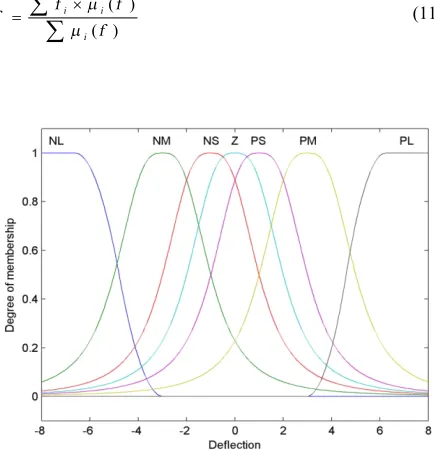
Bell-shaped membership functions are used to model the inputs and outputs. By choosing these membership functions, each input signal is assigned to all linguistic groups which can reduce the ambiguity in the border areas. Figures2 and 3 show the bell-shaped membership functions chosen for FIS inputs, and Figure 4 shows the bell-shaped membership functions chosen for the output. In these figures NL, NM, NS, Z, PS, PM and PL denote negative large, negative medium, negative small, zero, positive small, positive medium and positive large, respectively. Inputs and output cured face of fuzzy inference is illustrated in Figure 5.The following control rule is applied in fuzzy controller:
If x is A and y is B, then z is C The total rule base which contains 49 control rules is represented in Table 1. Center of gravity method is used as defuzzification process. So, the control input is determined as Equation (11) in which µi(f) represents the membership functions. The results of this fuzzy controller are used to train the ANFIS system.
( ) ( )
i i
i
f f
f
f
m m
´
=
å
å
(11)Figure 2. Membership functions for first input (Deflection)
Figure 3. Membership functions for second input (Velocity)
Figure 4. Membership functions for output
Figure 5. Inputs and output cured face for fuzzy inference
As stated before, in fuzzy method, there is not a standard algorithm to define the membership functions and control rules which cause the error in control process and decrease the performance of the system.
TABLE 1. Total rule base on fuzzy controller
FIS_input1
FIS_input2 NL NM NS Z PS PM PL
NL NL NL NM NS NS NS Z
NM NL NM NS Z NS Z PS
NS NM NS Z Z Z PS PM
Z NM NS Z Z Z PS PM
PS NM NS Z Z Z PS PM
PM NS Z PS Z PS PM PL
PL Z PS PS PS PM PL PL
In fact, the ANFIS controller is a method that usesthe knowledge-based and neural learning approach, simultaneously.Because of the linguistic statements from the rule base of the ANFIS controller, the control strategy resembles human thinking process. The ANFIS based controller isexplained in this section which can create the membership functions and rules automatically based on training data. To design an ANFIS controller,an appropriatedatabase is needed.
To create the database, the results of the fuzzy controller proposed in this paper a LQR controller [1] and a sliding mode controller [10] are used. By extracting thedeflection and velocity for each controller and combination of these data, anappropriatedatabase is created. This database is applied to train the ANFIS controller. After training the ANFIs using Hybrid method, ANFIS creates 49 if-then rules.
4. SIMULATIONS AND DISCUSSION
In this section, simulation results are presented for proposed ANFIS based suspension system. For the quarter car model, parameters are considered as follows: m=250kg, mw=50kg, kb=16000N/m, kw=160000N/m and bb=1500Ns/m. To examine the performance of the system, two types of road disturbances are considered. The first disturbance is a pulse which is defined in Equation (12).
0 .1, 1 4
0 ,
r
t Z
o th erw ise < < ì
= í
î (12)
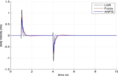
Figure 6 shows the suspension systems vertical displacement for different controllers and passive system. It is shown that the ANFIS system has better result compared to other systems. Body velocity and acceleration are shown in Figures 7 and 8, respectively. The results clearly show that the proposed ANFIS system has better performance compared to passive, LQR and fuzzy systems. The velocity and acceleration of the vehicle have reduced in the proposed system, which can provide the comfort riding.
Figure 9 illustrates the control force for different systems. It is quite clear from this figure that the ANFIS controller uses little control force as compared to LQR and fuzzy systems, and it is energy optimal. The second type of disturbance is considered as follows:
0.14(1 cos(8 ))
, 0.5 0.75 2
0.08(1 co s(8 )), 3.5 3.75 2
0,
r
t
t
t
Z t
o therw ise
p
p
-ì < <
ï ï
-ï
=í < <
ï ï ïî
(13)
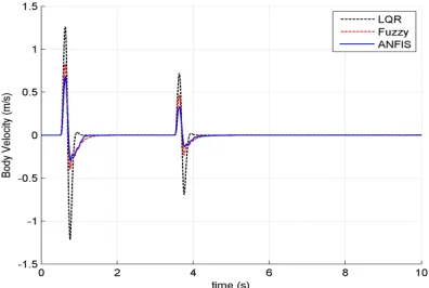
The simulation results for this disturbance are illustrated in Figures 10, 11, 12 and 13. As it is shown in these figures, the ANFIS system has better performance compared to passive system, fuzzy and LQR systems which can cause good handling for the vehicle. Also, the proposed system has significant reduction in control force as compared with LQR and fuzzy controllers. Figure 14 shows the body displacement for the first road disturbance with different magnitude. It is shown that the ANFIS controller allows a fast rise time and quick settling time without oscillatory behavior. Simulation show that the ANFIS controller givessuitable results for pulse and sinusoidal function road disturbances effectively, and hence it can be said that this controller could handle other real road situations.
Figure 6. Body displacement for first road disturbance
Figure 8. Body acceleration for first road disturbance
Figure 9. Control force for first road disturbance
Figure 10. Body displacement for second road disturbance
Figure 11. Body velocity for second road disturbance
Figure 12. Body acceleration for second road disturbance
Figure 13. Control force for second road disturbance
Figure 14. Body displacement for first road disturbance with different magnitude
5. CONCLUSIONS
it can guarantee a comfort ride and good handling. The discussion about suspension problem in full car model is the subject that authors hope to study in near future using the main concepts of this paper.
6. REFERENCES
1. Kaleemullah, M., Faris, W.F. and Hasbullah, F., "Design of robust h∞, fuzzy and lqr controller for active suspension of a quarter car model", in Mechatronics (ICOM), 4th International Conference On, IEEE. (2011), 1-6.
2. Foda, S.G., "Fuzzy control of a quarter-car suspension system", in Proceedings of the 12th International Conference on Microelectronics. (2000), 231-234.
3. Lauwerys, C., Swevers, J. and Sas, P., "Design and experimental validation of a linear robust controller for an active suspension of a quarter car", in American Control Conference, Proceedings, IEEE. Vol. 2, (2004), 1481-1486.
4. Thompson, A., "An active suspension with optimal linear state feedback", Vehicle System Dynamics, Vol. 5, No. 4, (1976), 187-203.
5. Thompson, A. and Davis, B., "Optimal linear active suspensions with vibration absorbers and integral output feedback control",
Vehicle System Dynamics, Vol. 18, No. 6, (1989), 321-344. 6. Cheok, K.C., Loh, N.-K., McGee, H.D. and Petit, T.F., "Optimal
model-following suspension with microcomputerized damping",
Industrial Electronics, IEEE Transactions on, No. 4, (1985), 364-371.
7. Esmailzadeh, E. and Taghirad, H., "Active vehicle suspensions with optimal state-feedback control", International Journal of Modelling and Simulation, Vol. 18, No., (1998), 228-238.
8. Aubouet, S., Dugard, L. and Sename, O., "H∞/lpv observer for an industrial semi-active suspension", Control Applications, (CCA) & Intelligent Control, (2009), 756-763.
9. Lin, J.-S. and Kanellakopoulos, I., "Nonlinear design of active suspensions", Control Systems, IEEE, Vol. 17, No. 3, (1997), 45-59.
10. Sam, Y.M., Osman, J.H. and Ghani, M.R.A., "A class of proportional-integral sliding mode control with application to active suspension system", Systems & Control Letters, Vol. 51, No. 3, (2004), 217-223.
11. Yoshimura, T., "Active suspension of vehicle systems using fuzzy logic", International Journal of Systems Science, Vol. 27, No. 2, (1996), 215-219.
12. Rao, M. and Prahlad, V., "A tunable fuzzy logic controller for vehicle-active suspension systems", Fuzzy Sets And Systems, Vol. 85, No. 1, (1997), 11-21.
13. Campos, J., Lewis, F., Davis, L. and Ikenaga, S., "Backstepping based fuzzy logic control of active vehicle suspension systems", in American Control Conference, Proceedings of IEEE. Vol. 6, (2000), 4030-4035.
14. Lauwerys, C., Swevers, J. and Sas, P., "Robust linear control of an active suspension on a quarter car test-rig", Control Engineering Practice, Vol. 13, No. 5, (2005), 577-586. 15. Park, S. and Rahmdel, S., "A new fuzzy sliding mode controller
with auto-adjustable saturation boundary layers implemented on vehicle suspension", International Journal of Engineering-Transactions C: Aspects, Vol. 26, No. 12, (2013), 1401. 16. Bagheri, A. and Mahmoodabadi, M., "Pareto optimization of a
two-degree of freedom passive linear suspension using a new multi-objective genetic algorithm (technical note)",
International Journal of Engineering-Transactions A: Basics, Vol. 24, No. 3, (2011), 291-301.
Active Suspension System Control Using Adaptive Neuro Fuzzy (ANFIS) Controller
H. Moghadam-Fard, F. Samadi
Control Engineering Department, Faculty of Electrical and Computer Engineering, University of Tabriz, Tabriz, Iran
P A P E R I N F O
Paper history:
Received 17 February 2014 Received in revised form 28 June 2014 Accepted 13November 2014
Keywords:
Active Suspension System Fuzzy Logic Controller ANFIS
Quarter Car Model
ﺪﯿﮑﭼ ه
ﻞﯿﺒﻣﻮﺗانﺎﻨﯿﺸﻧﺮﺳ وهﺪﻨﻧارياﺮﺑﯽﺘﺣار وﺶﯾﺎﺳآ ندﻮﻤﻧﻢﻫاﺮﻓ ،لﺎﻌﻓﻖﯿﻠﻌﺗﻢﺘﺴﯿﺳﮏﯾﯽﺣاﺮﻃزافﺪﻫ
ﻬﺟاﻮﻣرد
ﻪ ﺎﺑ
يراﻮﻤﻫﺎﻧ
ﯽﻣهدﺎﺟيﺎﻫ
ﺪﺷﺎﺑ
.
ﻢﺘﺴﯿﺳياﺮﺑﯽﻘﯿﺒﻄﺗﯽﺒﺼﻋيزﺎﻓجﺎﺘﻨﺘﺳاﻢﺘﺴﯿﺳسﺎﺳاﺮﺑيﺪﯾﺪﺟﯽﻟﺮﺘﻨﮐشورﻪﻟﺎﻘﻣﻦﯾارد
ﻖﯿﻠﻌﺗ
ﯽﻣدﺎﻬﻨﺸﯿﭘلﺎﻌﻓ
دﻮﺷ
.
هدادهﺎﮕﯾﺎﭘبﺎﺨﺘﻧاوﻪﯿﻬﺗ
شزﻮﻣآياﺮﺑﺐﺳﺎﻨﻣي
ANFIS
ﯽﯾارﺎﮐﺶﯾاﺰﻓاردارﯽﻤﻬﻣﺶﻘﻧ
ﯽﻣﺎﻔﯾاﻢﺘﺴﯿﺳ
ﺪﻨﮐ
.
هدادهﺎﮕﯾﺎﭘ
،يزﺎﻔﯾﺎﻫﺮﻟﺮﺘﻨﮐﯽﺟوﺮﺧزا،هدﺎﻔﺘﺳادرﻮﻣي
LQR
ﺖﺳاهﺪﺷﻪﯿﻬﺗﯽﺷﺰﻐﻟﺪﻣو
.
ﻊﺑرلﺪﻣﮏﯾ
ﻪﯿﺒﺷياﺮﺑوردﻮﺧ
ﺸﯿﭘﻢﺘﺴﯿﺳﯽﯾارﺎﮐﯽﺳرﺮﺑويزﺎﺳ
ﺖﺳاهﺪﺷﻪﺘﻓﺮﮔﺮﻈﻧرد،يدﺎﻬﻨ
.
دﺮﮑﻠﻤﻋﺎﺑيدﺎﻬﻨﺸﯿﭘﻢﺘﺴﯿﺳدﺮﮑﻠﻤﻋ
ﻢﺘﺴﯿﺳولﺎﻌﻓﺮﯿﻏﻢﺘﺴﯿﺳ
هﺪﻨﻨﮐلﺮﺘﻨﮐﺎﺑلﺎﻌﻓيﺎﻫ
ويزﺎﻔﯾﺎﻫ
LQR
ﺖﺳاهﺪﺷﻪﺴﯾﺎﻘﻣ
.
ﻪﯿﺒﺷﺞﯾﺎﺘﻧ
يﺰﻠﺳ
ﯽﻣنﺎﺸﻧﺎﻫ
ﻪﮐﺪﻫد
ﺮﻟﺮﺘﻨﮐ
ANFIS
ﺮﺘﻬﺑ،ﯽﻟﺮﺘﻨﮐيوﺮﯿﻧوﺖﺴﺸﻧنﺎﻣز،ﻪﻧﺪﺑبﺎﺘﺷ،ﻪﻧﺪﺑﯽﯾﺎﺠﺑﺎﺟظﺎﺤﻟزاهﺪﺷﯽﺣاﺮﻃ
ﻢﺘﺴﯿﺳزا
ﯽﻣﻦﯿﺸﯿﭘيﺎﻫ
-ﺪﺷﺎﺑ
.
![Figure 1. Quarter car suspension model [1]](https://thumb-us.123doks.com/thumbv2/123dok_us/228138.2017369/2.595.83.223.572.732/figure-quarter-car-suspension-model.webp)