IJE Transactions B: Applications Vol. 24, No. 2, July 2011 -
155
DYNAMIC ANALYSIS OF A THREE-ROTOR FLEXIBLE
COUPLING WITH ANGULAR MISALIGNMENT
M. Akhondizadeh. Korrani*
Mechanical Engineering Department of Shahid Bahonar University of Kerman, Kerman-Iran [email protected]
M. Fooladi. Mahani
Mechanical Engineering Department of Shahid Bahonar University of Kerman, Kerman-Iran [email protected]
*Corresponding Author
(Received: July 26, 2009 – Accepted in Revised Form: April 23, 2011)
Abstract In this paper, the dynamic response of a three-rotor flexible coupling to the angular misalignment has been studied. The coupling is a power transmission agent between the motor and gearbox, in the power transmission system of SAG Mill (semi autogenously mill) in the Gol-e-Gohar iron ore complex in Sirjan, Iran. Degrees of freedom of the system are the model's lateral deflections and the rigid-body linear motions. The equations of motion are obtained by using the Lagrange equations through successive partial differentiation of the kinetic and potential energies. In the dynamic model, the middle rotor is considered as an eccentric flexible Jeffcott rotor. The gearbox input shaft is considered to be angularly misaligned with respect to the motor shaft. Diagrams of the amplitudes versus the frequency ratio reveal the system dynamic response to the angular misalignment.
Keywords Rotor dynamic, Flexible coupling, Misalignment, Vibration,
ﻩﺪﻴﻜﭼ
ﺩﺦﺳﺎﭘ،ﺮﺿﺎﺣ ﺭﺎﮐﺭﺩ ﻳ
ﻣﺎﻨ ﻴ ﮑ ﻲ ﻳ ﻠﭘﻮﮐﮏ ﻴ ﻑﺎﻄﻌﻧﺍﮓﻨ ﺬﭘ
ﻳﺮ ﻢﻫﺎﻧﺎﺑﺭﻮﺗﻭﺭﻪﺳﻞﻣﺎﺷ ﺎﺘﺳﺍﺭ
ﻲﻳ ﻭﺍﺯ ﻳﻪ ﺍ ﻱ ﺩﺭﻮﻣ
ﺳﺭﺮﺑ ﻲ ﺭﺍﺮﻗ ﺖﺳﺍ ﻪﺘﻓﺮﮔ .
ﺍﻳ ﻠﭘﻮﮐﻦ ﻴ ﺑﺕﺭﺪﻗ ﻝﺎﻘﺘﻧﺍﻂﺳﺍﻭ،ﮓﻨ ﻴ
ﮔﻭﺭﻮﺗﻮﻣﻦ ﻴ
ﺳﺭﺩﺲﮑﺑﺮ ﻴ
ﺳﺁﺕﺭﺪﻗﻝﺎﻘﺘﻧﺍﻢﺘﺴ ﻴﺎ
ﻱ
ﻧﻴ ﺳﺮﻬﮔﻞﮔﻦﻫﺁﮓﻨﺳﻥﺪﻌﻣﻦﮑﺷﺩﻮﺧﻪﻤ ﻴ
ﺍﺭﺩﻥﺎﺟﺮ ﻳ ﺖﺳﺍﻥﺍﺮ . ﺩﺍﺯﺁﺕﺎﺟﺭﺩ ﻱ
ﺳﻴ ﺒﻧﺎﺟﻑﺎﻄﻌﻧﺍ،ﻢﺘﺴ ﻲ
ﺳﺭﺩ ﻴ ﻭﻢﺘﺴ
ﻄﺧ ﺕﺎﮐﺮﺣ ﻲ
ﺪﻨﺘﺴﻫﺐﻠﺻﻢﺴﺟ .
ﺳ ﺖﮐﺮﺣﺕﻻﺩﺎﻌﻣ ﻴ
ﺩﺵﻭﺭﺎﺑﻢﺘﺴ ﻳ
ﻣﺎﻨ ﻴ ﮋﻧﺍﺮﮔﻻﮏ ﻱ
ﻖﺘﺸﻣﺎﺑﻭ ﮔﻴ
ﺮ ﻱ ﭘﻴ ﭘﺎ ﻲ ﺯﺍ
ﮊﺮﻧﺍ ﻱ ﺎﻫ ﻱ ﺸﺒﻨﺟ ﻲ ﺴﻧﺎﺘﭘ ﻭ ﻴ ﻣ ﺝﺍﺮﺨﺘﺳﺍ ﻞ ﻲ
ﺪﻧﻮﺷ . ﺩ ﻝﺪﻣ ﺭﺩ ﻳ
ﻣﺎﻨ ﻴ ﮑ ﻲ ﻣ ﺭﻮﺗﻭﺭ ، ﻴﻧﺎ ﻲ ، ﻳ ﻑﺎﻄﻌﻧﺍ ﺭﻮﺗﻭﺭ ﮏ ﺬﭘ
ﻳﺮ ﻝﺪﻣ
ﺕﺎﮑﻔﺟ ﺍﺭﺍﺩ ﻱ ،ﺰﮐﺮﻣﺯﺍﺝﻭﺮﺧ ﻩﺪﺷﻪﺘﻓﺮﮔﺮﻈﻧﺭﺩ
ﺖﺳﺍ . ﻢﻫﺎﻧ ﺎﺘﺳﺍﺭ ﻲﻳ ﻭﺍﺯ ﻳﻪ ﺍ ﻱ ﺍﺮﺑ ﻱ ﺩﻭﺭﻭﺭﻮﺤﻣ ﻱ
ﮔﻴ
ﺖﺒﺴﻧﺲﮑﺑﺮ
ﺟﻭﺮﺧﺭﻮﺤﻣ ﻪﺑ ﻲ
ﻣﻪﺘﻓﺮﮔﺮﻈﻧﺭﺩ ﺭﻮﺗﻮﻣ ﻲ
ﺩﻮﺷ . ﺎﻫﺭﺍﺩﻮﻤﻧ ﻱ ﺒﺴﻧ ﺲﻧﺎﮐﺮﻓ ﺐﺴﺣﺮﺑﻪﻨﻣﺍﺩ ﻲ
ﺳﺦﺳﺎﭘ ، ﻴ ﻢﻫﺎﻧ ﻪﺑﻢﺘﺴ
-ﺎﺘﺳﺍﺭ ﻲﻳ ﻭﺍﺯ ﻳﻪ ﺍ ﻱ ﻣﺭﺎﮑﺷﺁﺍﺭ ﻲ ﺩﺯﺎﺳ .
1. INTRODUCTION
Couplings are widely used in industry to transmit the power from the driver to the driven rotors. Generally, there are two types of connections in couplings: rigid and flexible. Rigid couplings have low deflections; however, they insert additional force and moments on the system equipments such as motor, bearings and gearbox. Flexible couplings are used to eliminate the additional force and moments; however, their position changes may be resulted in high level vibrations that can damage the system and lead to shutdown.
Misalignment of the connected rotors is one of the most common defects that may be encountered. It may cause undesired vibrations. Many factors affect the vibration behavior of a misaligned system. Therefore the phenomenon must be well understood so that it can be detected and adjusted at the initial stages of its appearance.
There are a lot of discussions in industry regarding the interpretation of the vibration signals introduced due to misalignment, but there is not enough academic research to explain the phenomenon in a simple way.
156
- Vol. 24, No. 2, July 2011 IJE Transactions B: Applicationsmisalignment, to aid turbo machinery diagnostic
engineers in understanding the dynamic response of a misaligned system. He proposed future works such as angular misalignment and axial motions. Lorenzen et al. [2] compared the critical speeds of a high-speed high-power compressor train that alternatively equipped with the solid couplings, flexible-disc and gear-type couplings. They showed that the solid couplings can cause the rotor to be more stable. Sekhar and Prabhu [3] explained the effect of the coupling misalignment on the turbo machinery vibrations. They showed that the location of the coupling has a strong influence on the level of vibrations. A theoretical model of a complete system of the motor-flexible coupling rotor was presented by Xu and Marangoni [4]. They assumed that the flexible coupling behaves exactly like a universal joint to take the misalignment effect into account. Prabhu [5] experimentally investigated the effect of misalignment on the cylindrical and three-lobe journal bearings. He showed that an increase in the angular misalignment caused change in the second harmonic of the vibration response. Simon [6] predicted the behavior of a large imbalanced turbo machine, imposed by the misalignment. He computed numerically the vibration, excited by the coupling, using the assumed values for the coupling reaction force and moments.
Diagnostic engineers of the Gol-e-Gohar industry aimed to develop a VCM (vibration condition monitoring) process on the power transmission system of the SAG Mill. Misalignment is one of the common system defects, so its dynamic effects must be good understood. In the present work the system dynamic response to the angular misalignment has been investigated.
2. GEOMETRY DESCRIPTION
The system that transmits power between a 3Mwatt-motor and the gearbox of a SAG Mill is studied here. It is composed of output motor-side shaft, flexible coupling and gearbox input shaft. The flexible coupling is illustrated in Figure 1. The motor shaft and gearbox input shaft are located inside the hubs 1 and 3 respectively. The geometrical system properties are shown in Table 1.
TABLE1. Geometrical system properties
Shaft Length
(mm) Diameter (mm)
Length to diameter ratios
Motor shaft 320 220 1.45
Flexible shaft 1260 Do =368, Di =324 3.42
Gearbox shaft 240 220 1.1
Figure 1. Coupling with steel plates as the flexible elements
3. DYNAMIC MODEL
The system model with angular misalignment is illustrated in Figure 2. The angular misalignment of the gearbox input shaft relative to the motor output shaft is taken as a pure rotation around the y
axis as shown in Figure 2. In this figure, γ is the angular misalignment magnitude and α is the orientation change of rotor 2 due to the misalignment.
Figure 2. Model of the misaligned system
IJE Transactions B: Applications Vol. 24, No. 2, July 2011 -
157
motion, and the point o corresponds to the end
position of rotor 2 at this instant. The length-diameter ratios of rotors 1 and 3 are such that they can be considered as rigid cylinders.
4. KINETIC AND POTENTIAL ENERGIES
The Lagrange energy method is used to obtain the equations of motion. The generalized coordinates for the 13 degrees of freedom of the system are:
q = {x1 , y1 , z1, β1, xo , yo , zo , xr2 , yr2 , x3 , y3 , z3, β3} (1)
Figure 3. Position of rotor 2 at an instant of the motion Independent coordinates, r and β2=ωt, specify the position of center mass of rotor 2 with respect to its ends but, in the present study, they have been replaced by the coordinates xr2 and yr2 respectively. So, the position of the center of mass of rotor 2 with respect to its static state is specified as follows: x2 = xo + xr2 (2)
y2 = yo + yr2 (3)
xr2 = r sinωt + ε sin(ωt+φ) (4)
yr2 = r cosωt + ε cos(ωt+φ) (5)
The rotations of rotor 2 around the x and y axes have been ignored. Therefore: z2 = zo (6)
the system kinetic energy is: T = T1 + T2 + T3 (7)
2 3 3 2 3 2 3 2 3 3 2 2 2 2 2 2 2 2 2 2 1 1 2 1 2 1 2 1 1 2 1 ) ( 2 1 2 1 ] ) ( ) [( 2 1 2 1 ) ( 2 1 β β β & & & & & & & & & & & & & & I z y x m I z y y x x m I z y x m T o r o r o + + + + + + + + + + + + + =
(8)
and the potential energy is: U = Ubm + Ubg + U2 + Uc1 + Uc2 (9)
It is assumed that the bearings are linearly flexible and their potential energy is as follows[1]: 2 1 2 1 2 1 2 1 2 1 2 1 z k y k x k Ubm = bmx + bmy + bmz (10)
2 3 2 3 2 3 2 1 2 1 2 1 z k y k x k Ubg = bgx + bgy + bgz (11)
The potential energy of the flexible connections is due to the relative motion of the ends of rotor 2 with respect to the rotors 1 and 3 [7]. The end displacements of rotor 2 in direction of rotors 1 and 3 can be written by using unit vectors as: rc21 = (xo cosα – zo sinα)i1 + yo j1 + (xo sinα + zo cosα)k1 (12)
rc23 = [xo cos(γ - α) – zo sin(γ - α)]i3 + yo j3 + [xo sin(γ - α) + zo cos(γ - α)]k3 (13)
then, the potential energy of the connection is: 2 1 2 1 2 1 21 } cos sin { 2 1 ) ( 2 1 } sin cos { 2 1 z z x k y y x z x k U o o cz o o o cx c − + + − + − − = α α α α (14)
2 3 2 3 2 3 23 } ) cos( ) sin( { 2 1 ) ( 2 1 } ) sin( ) cos( { 2 1 z z x y y k x z x k U o o o cy o o cx c − − + − + − + − − − − = α γ α γ α γ α γ (15)
Bending potential energy of rotor 2 is: } )] cos( [ )] sin( {[ 2 1 2 1 2 2 2 2 2 2 2 2 ϕ ω ε ϕ ω ε + − + + − = = t y t x k r k U r r (16)
158
- Vol. 24, No. 2, July 2011 IJE Transactions B: Applications} )) cos( ( )) sin( {( 2 1 } ) cos( ) sin( { 2 1 ) ( 2 1 } ) sin( ) cos( { 2 1 } cos sin { 2 1 ) ( 2 1 } sin cos { 2 1 2 1 2 1 2 1 2 1 2 1 2 1 2 2 2 2 2 2 3 2 3 2 3 2 1 2 1 2 1 2 3 2 3 2 3 2 1 2 1 2 1 ϕ ω ϕ ω α γ α γ α γ α γ α α α α + − + + − + − − + − + − + − − − − + − + + − + − − + + + + + + = t e y t e x k z z x k y y k x z x k z z x k y y k x z x k z k y k x k z k y k x k U r r o o cz o cy o o cx o o cz o cy o o cx bgz bgy bgx bmz bmy bmx (17)
5. EQUATIONS OF MOTION
Equation (18) ( Lagrange's equation) is used to obtain the equations of motion.
n i Q q T q U q T dt d i i i i ,..., 3 , 2 , 1 , ) ( = = ∂ ∂ − ∂ ∂ + ∂ ∂ & (18)
where, n is the number of generalized coordinates and
Qi is the generalized force(or moment) in direction of qi.
) sin cos ( ) ( } sin cos { ) ( ) ( 1 1 1 1 1 1 1 1 1 1 1 1 1 1 1 α α α α o o cx cx bmx x x o o cx bmx x z x k x k k x C x m x C x z x k x k x m dt d Q x T x U x T dt d − = + + + − = − − − + = ∂ ∂ − ∂ ∂ + ∂ ∂ & & & & & &
(19) o cy cy bmy
y y k k y k y
C y
m1&&1+ 1&1+( + ) 1= (20)
) cos sin ( ) ( 1 1 1 1 1 α α o o cz cz bzm z z x k z k k z C z m + = + + + & & &
(21) )] sin( ) cos( [ ) ( 3 3 3 3 3 α γ α
γ− − −
= + + + o o cx cx bgx x z x k x k k x C x
m && &
(22) o cy cy bgy
y y k k y k y
C y
m3&&3+ 3&3+( + ) 3 = (23)
)] cos( ) sin( [ ) ( 3 3 3 3 3 α γ α
γ − + −
= + + + o o cz cz bgz z z x k z k k z C z
m && &
(24)
It can be inferred from Equations (19)-(24) that the dynamic of rotors 1 and 3 is highly dependent on the end movement of rotor 2.
Equations of motion of rotor 2 are:
0 )] sin( [ ) ( ) ( 2 2 2 2 2 2 2 2 = + − + + = ∂ ∂ − ∂ ∂ + ∂ ∂ ϕ ω ε t x k x x m Q x T x U x T dt d r o r xr r r r & & & & &
(25)
Substituting xr2 from Equation (4) into Equation (25) leads to:
t r k t t r m x m o ω ϕ ω ε ω ω sin )] sin( sin [ 2 2 2 2 − + + = & &
(26)
At the steady state, r and φ are independent of time and can be expressed as Equations (27). [10]
] ) ( 1 2 [ tan ) ( ) ) ( 1 ( ) 2 ( ) ( ) ( 2 2 2 2 1 2 2 2 2 2 2 2 2 n n n n n r ω ωω ω ξ ω ϕ ω ω ω ω ξ ω ω ε ω − = − + = −
(27) where 2 2 2 m k n =
ω and
2 2 2 2
2 km
C
=
ξ (28)
are the bending natural frequency and damping ratio of rotor 2.
Therefore, the solution of Equation (26) can be given as: ) cos( ) ( ) ,
( o xo
o t X t
x ω = ω ω −θ (29)
where ] sin cos ) ( [ tan ) ( sin ] cos ) ( [ ) ( 2 2 1 2 2 2 2 2 ϕ ε ϕ ε ω ω ω θ ϕ ε ϕ ε ω ω ω − − − = + − − =
− r r
r r X n xo n o (30)
The equation of motion of rotor 2 in direction of y
is solved in the same way as that for direction of x, to obtain the end displacement, yo, as a function of time and rotational frequency.
IJE Transactions B: Applications Vol. 24, No. 2, July 2011 -
159
] cos ) ( sin [ tan ) ( sin ] cos ) ( [ ) ( 2 2 1 2 2 2 2 2 ϕ ε ω
ω ε ϕ ω θ ϕ ε ϕ ε ω ω ω − − = + − − = − r r r r Y n yo n o (32) 6. SOLUTIONS
Substituting Equations (29) and (31) into Equations (19) to (24):
)
cos(
)
(
)
(
1 1 1 1 1 yo o cy cy bmy yt
Y
k
y
k
k
y
C
y
m
θ
ω
ω
−
=
+
+
+
&
&
&
(33)It is assumed that:
)
(
Re
)
,
(
1 1 t ie
Y
al
t
y
ω
=
ω (34)where i = √-1. Substituting y1(t,ω) from Equation (34) into the Equation (33) leads to:
0 ) ( )] ( [ 1 1 1 1 1
2 i y
o cy cy bmy y e Y m k Y m k k m C
i ω ω θ
ω + + + = −
− (35)
solution of Equation (35) for Y1, gives:
) ( 2 2 1 2 1 1 1 1 ] ) ( 1 [ ) 2 ( ) ( )
( i yo y
y n bmy cy y n y o bmy cy e k k Y k k
Y θ θ
ω ω ω ω ξ ω
ω − +
− + +
= (36)
where 1 1 m kbmy y n = ω
,
1 1 12 k m
C bmy y y = ξ
,
] ) ( 1 2 [ tan 2 1 1 1 1 1 y n bmy cy n y y k k ω ω ω ω ξ θ − += − (37)
Therefore: ) cos( ] ) ( 1 [ ) 2 ( ) ( ) , ( 1 2 2 1 2 1 1
1 yo y
y n bmy cy y n y o bmy cy t k k Y k k t
y ω θ θ
ω ω ω ω ξ ω
ω − −
− + + =
(38)
Equation (19), which is a couple equation of x1, xo and zo, is solved to determine x1(t,ω). A reasonable assumption that zo is a harmonic function in phase with xo, simplifies the solution of Equation (19).
)
cos(
)
,
(
o xoo
t
Z
t
z
ω
=
ω
−
θ
(39)Substituting Equations (39) and (29) into Equation (19), leads to:
) cos( ] sin cos ) ( [ ) ( 1 1 1 1 1 1 1 xo o o cx cx bmx x t Z X m k x m k k x m C x θ ω α α ω − − = + + + & &
& (40)
A solution for the Equation(40) would be:
)
)
(
(
Re
)
,
(
1 1 t ie
X
al
t
x
ω
=
ω
ω (41)Substituting Equation (41) into Equation (40) leads to: ) cos( ] ) ( 1 [ ) 2 ( ] sin cos ) ( [ ) , ( 1 2 2 1 2 1 1
1 xo x
x n bmx cx x n x o o bmx cx t k k Z X k k t
x ω θ θ
ω ω ω ω ξ α α ω
ω − −
− + +
−
= (42)
Where 1 1 2 1 1 1 1 1 1 1
1 ],
) ( 1 2 [ tan , 2 m k k k m k C bmx x n x n bmx cx x n x x bmx x x = − + = = − ω ω ω ω ω ξ θ ξ (43)
Solution of Equation (21) by the same method as Equation (19) leads to:
) cos( ] ) ( 1 [ ) 2 ( ] cos sin ) ( [ ) , ( 1 2 2 1 2 1 1
1 xo z
z n bmz cz z n z o o bmz cz t k k Z X k k t
z ω θ θ
ω ω ω ω ξ α α ω
ω − −
− + + + = (44) where , ] ) ( 1 2 [ tan , 2 2 1 1 1 1 1 1 1 1 1 1 z n bmz cz z n z z bmz z n bmz z z k k m k m k C ω ω ω ω ξ θ ω ξ − + = = = − (45)
160
- Vol. 24, No. 2, July 2011 IJE Transactions B: ApplicationsTABLE 2. System mechanical parameters
kcx kcy kcz
1.22 GN/m 1.22 GN/m 0.735GN/m
m1 m2 m3
313 kg 313 kg 289 kg
Equation (46) is used to calculate the stiffness of roller bearings [8].
Keq = 3×10⁵N0.9L0.8P0.1cos1.9α1 (lb/in) (46) Therefor the stiffness of the motor-side bearing
would be:
kbm = 3×10 5
×190.9×1.970.8×1046.40.1 = 146.4×10⁵ lb/in = 2.53 GN/m (47) Bending stiffness of rotor 2, as a beam, can be calculated as follow: [9]
m
N
l
EI
k
48
3
.
6
*
10
8/
32 2
2
=
=
(48)7. NUMERICAL RESULTS
To study the effect of rotational frequency on the dynamic response of the system, results of the case study where Zo/ε = 2 and α =7 degrees were calculated. It should be noted that α is not the angular misalignment magnitude, and is the rotor 2
orientation change due to the misalignment. Dimensionless form of the amplitude function of
rotor 1 in direction of z1 is written as:
2 2 1 2
1 1
2 2 2
1 1
2 1
] ) ( 1 [ ) 2 (
] cos sin
] cos ) )( ( [ [sin ) (
z n bmz
cz z n z
o z
n z n n bmz
cz
k k
Z r
r k
k Z
ω ω ω
ω ξ
α ε ϕ ϕ ε ω ω ω
ω ε α ε
ω
− + +
+ + − − =
(49)
In the Equation (49), r and φ depend on the rotational velocity, eccentricity value, damping ratio and bending stiffness of rotor 2. After substituting Equation (27) into Equation (49), the dimensionless amplitude Z1/ε would be a function of the rotating frequency only. The dimensionless
amplitude of rotor 1 in x and y directions as the functions of rotational frequency can be obtained by the same procedure as that of z direction. Variations of the dimensionless amplitudes versus the frequency ratio, for damping ratios of 0.05-1, have been illustrated in Figures 4 to 8.
Figure4. Dimensionless amplitude of rotor 1 in z direction (Z1/ε), versus the frequency ratio (ω/ωn1z)
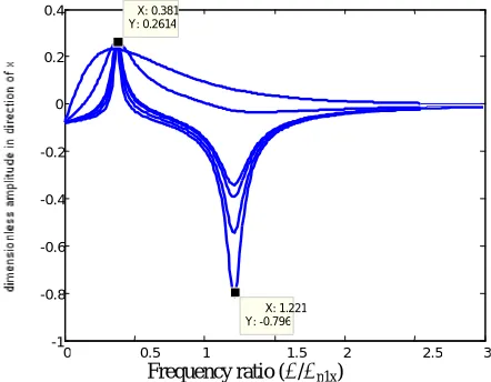
Figure 5. Dimensionless amplitude of rotor 1 in x direction (X1/ε), versus the frequency ratio (ω/ωn1x)
0 0.5 1 1.5 2 2.5 3
-1 -0.8 -0.6 -0.4 -0.2 0 0.2
0.4 X: 0.381 Y: 0.2614
Frequency ratio (ω/ωn1x)
X: 1.221 Y: -0.796
0 0.5 1 1.5 2 2.5 3
0 1 2 3 4 5 6 7 8 9 10
IJE Transactions B: Applications Vol. 24, No. 2, July 2011 -
161
Figure 6. Dimensionless amplitude of rotor 1 in y direction (Y1/ε), versus the frequency ratio (ω/ωn1y)
Figure 7. Dimensionless deflection of rotor 2 (r/ε), versus the frequency ratio (ω/ωn2)
Figure 8. Dimensionless end movement of rotor 2 (Xo/ε),
versus the frequency ratio (ω/ωn2)
Figures 4-6 show resonances on the frequency spectrums of rotor 1 that corresponds to the frequency ratios of 0.38 and 1.2 for the spectrums of x and y directions, and the frequency ratio of 1.32 for the spectrum of z direction. The resonance frequency ratios of the x and y directions are equal because:
kcx= kcy and kbmx= kbmy.
As is shown in Figure 8, when ω/ωn2=1 then
Xo/ε=1 The reason is clear from the Equation (50).
ϕ ϕ
ω ω ω
ω ξ
ω ω ε
ω
2 2 2
2 2 2
2 2
2
2 ) cos } sin
) ) ( 1 ( ) 2 (
] ) ( 1 [ {(
) (
+ −
− + − =
n n
n o
X
(50)
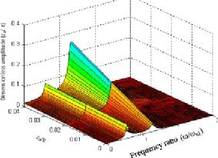
The first harmonic of Figures 5 and 6 is similar to that of Figure 8. This is because the first resonance arises from the excitation source harmonic, i.e., the rotor 2 harmonic. So, when the rotational frequency approaches the natural frequency of rotor 2, the resonance behavior of rotor 1 is similar to that of the end of rotor 2. This is not clear on the frequency spectrum of z direction in Figure(4), because the level of its second resonance is very high relative to the first one due to relatively high selected value for Zo/ε. Variation of the dimensionless amplitude of rotor 1 in z direction versus the frequency ratio and Zo/ε has been illustrated in Figure 9. It can be seen in this figure that for the small values of Zo/ε, the frequency spectrum of z direction is the same as the spectrums of x and ydirections.
Figure 9. Dimensionless frequency spectrum of rotor 1 in z
direction, versus Zo/ε and frequency ratio
0 0.5 1 1.5 2 2.5 3
0 0.1 0.2 0.3 0.4 0.5 0.6 0.7 0.8 0.9 1
Frequency ratio (ω/ωn2)
0 0. 1 1. 2 2. 3
0 1 2 3 4 5 6 7 8 9 1
Frequency ratio (ω/ωn2)
0 0. 1 1. 2 2. 3
0 0.05 0. 0.15 0. 0.25 0. 0.35 0.
X: 0.38 Y: 0.3509
Frequency ratio (ω/ωn1y)
162
- Vol. 24, No. 2, July 2011 IJE Transactions B: ApplicationsIt can be seen in Figures 4 to 6 that the resonance
frequency ratios do not correspond to the "1x" or "2x" of the rotational frequency, response characteristics commonly observed in the field of misaligned rotating shaft systems. The first harmonic at the spectrums corresponds to the case that ω=ωn2, however, it corresponds to the case that ω/ωn1x= ω/ωn1y=0.38. The second harmonic also corresponds to the case:
0
)
(
1
21
=
−
+
z n bmz
cz
k
k
ω
ω
(51) So, the harmonic of the frequency spectrums of
rotor 1 do not correspond to the frequency ratios of 1.
8. VARIATION OF THE MISALIGNMENT ANGLE
In this section, the effect of the angular misalignment on the system dynamic is investigated by providing the three dimensional amplitude diagrams versus the orientation change of rotor 2 (α) and the frequency ratio. In these diagrams, the large variation interval of α, [0, 0.4]… has been used so that its effects can be clearly shown. Otherwise, the value of α=0.4 radian is practically a very high angular misalignment value.
Figure 10. Three dimensional diagram of rotor 1 amplitude in
z direction
Figure 11. Three dimensional diagram of rotor 1 amplitude in
x direction
In Figure 11, the amplitude of x direction has been multiplied by "-1" so that its variation can be better shown. Figures 10 and 11 show that increasing of the misalignment angle increases the amplitude of rotor 1 slightly in z direction while, it increases significantly in x direction. The reason is due to the selected value of Zo/ε. the three dimensional diagram of amplitude in z direction for Zo/ε=.05 is illustrated in Figure 12, and shows the same response to misalignment as that in x direction.
Figure 12. Three dimensional diagram of rotor 1 amplitude in
z direction for Zo/ε=0.05
IJE Transactions B: Applications Vol. 24, No. 2, July 2011 -
163
9. SUMMARY AND CONCLUSIONS
In this study, a model for the lateral vibrations of three rotors subjected to the pure angular misalignment has been developed. The degrees of freedom of the system are the lateral deflections and the rigid-body rotation. The equations of motion of the system are obtained using the Lagrange equations through successive partial differentiations of the kinetic and potential energies. The equations of motion are coupled in the stiffness matrix and the force vector as a result of the presence of misalignment. The frequency spectrums revealed harmonics at the vibration amplitudes.
It is interesting that the foregoing study did not provide any evidence of the presence of harmonics of (1x) and (2x) which observed in the field of misaligned rotating systems.
Three dimensional diagrams of Figures 10 to 12, revealed that the angular misalignment would increase the axial and lateral vibration amplitudes. It is suggested that the nonlinearities of the bearing, rotation of rotor 2 around the y axis and the dynamic response of the parallel misalignment be studied. Work is currently underway to model the influence of these parameters on the vibration response of the system.
ACKNOWLEDGMENT
Authors would like to thank the assistance and supports of the Gol-e-Gohar Company for this research.
Nomenclature
E Modulus of elasticity
I2 Area moment of inertia of rotor 2 p
I
Polar mass moment of inertia of rotor p,p = 1, 2, 3
Keq Roller bearing's stiffness
k2 Bending stiffness of rotor 2
kcp Connection stiffness in direction of p,
p = x, y, z
kbmp Stiffness of the Motor side bearing in direction of p, p = x, y, z
kbgp Stiffness of the Gearbox side bearing in direction of p, p = x, y, z
l2 Length of rotor 2
L Length of the rollers of roller bearing
N Number of rollers of the roller bearings
P Load that is inserted on the roller bearing
rc21 Displacement vector of end of rotor 2 in direction of rotor 1 unit vectors
rc23 Displacement vector of end of rotor 2 in direction of rotor 3 unit vectors
Tp Kinetic energy of rotor p,
p = 1, 2, 3
U Total potential energy
U2 Bending potential energy of rotor 2
Ubm Potential energy of the motor side bearing
Ubg Potential energy of the gearbox side bearing
Uc21 Potential energy of the connection of the rotors 1 and 2
Uc23 Potential energy of the connection of the rotors 2 and 3
xp, yp, zp Displacement of rotor p in directions of
x, y and z p = 1, 2, 3
xo, yo, zo Rotor 2 end displacements in direction of x, y and z
xr2, yr2 Relative displacements of the center of mass and the end of rotor 2
Greek symbols
ε Eccentricity magnitude of rotor 2
γ Angular misalignment magnitude
α Orientation change of the spacer due to the angular misalignment
φ Phase delay of the deflection relative to the eccentricity of rotor 2
βp Rotation angle of rotor p p = 1, 2, 3
ξip Damping ratio of rotor p in direction of
i, p = 1, 2, 3, i = x, y, z
ξ2 Damping ratio of the rotor 2
ωnip Natural frequency of rotor p in direction of i, p = 1, 2, 3, i = x, y, z
164
- Vol. 24, No. 2, July 2011 IJE Transactions B: Applications10. REFERENCES
1. Al-Hussain, K. M. and Redmond, I. "Dynamic response of two rotors connected by rigid mechanical coupling with parallel misalignment" Journal of Sound and Vibration 249 (3) (2002) 483–498.
2. Lorenzen. H. E.A. Niedermann, W. Wattinger, "Solid couplings with flexible intermediate shafts for highspeed turbo compressor trains" Proceedings of the 18th turbo machinery Symposium, Dallas, TX, U.S.A. 101-110. 3. Sekhar, A. S. and Prabhu, B. S. Effects of coupling misalignment on vibrations of rotating machinery. Journal of Sound and vibration. (1995)185, 655-671.
4. Xu, M. and Marangoni, R. D. Vibration analysis of a motor-flexible coupling-rotor system subjected to
misalignment and unbalance. Part I: theoretical model analysis.Journal of Sound and vibration. (1994) 176, 663-679.
5. Prabhu, B. S. An experimental investigation on the misalignment effects in journal bearings. STLE Tribology Transaction. 1997s 40, 235-242.
6. Simon, G. Prediction of vibration of large turbo-machinery on elastic foundation due to unbalance and coupling misalignment. Proceedings of the Institution of Mechanical Engineers, (1992), Vol. 206, 299.
7. Al-Hussain, K. M. Dynamic stability of two rigid rotors connected by a flexible coupling with angular misalignment.
Journal of Sound and Vibration, 266 (2003) 217–234 8. Parshad, H. Relative comparison of stiffness and damping properties double ducker high precision and conventional rolling element bearings. tribology international,
volume 35, (2002)
9. Zhenwei Yuan, et al. External and internal coupling effects of rotor’s bending and torsional vibrations under unbalancesJournal of Sound and Vibration, 299, (2007), 339–347