Available Online at www.ijpret.com 48
INTERNATIONAL JOURNAL OF PURE AND
APPLIED RESEARCH IN ENGINEERING AND
TECHNOLOGY
A PATH FOR HORIZING YOUR INNOVATIVE WORK
DESIGN OF SPLITTER GEAR-BOX FOR MULTI HEAD CHAMFERING MACHINE
SAURABH R. LANJEWAR1, HARSHANAND P. RAMTEKE1, MANISH S. MARKE1, DR. G. D. MEHTA2, DR. J. P. MODAK3
1. Student of M-Tech (MED), Department of Mechanical Engineering, Priyadarshini College of Engineering, RashtraSant Tukdoji Maharaj Nagpur University (RTMNU)
2. Associate Professor, Department of Mechanical Engineering, Priyadarshini College of Engineering, RashtraSant Tukdoji Maharaj Nagpur University (RTMNU)
3. Dean (R&D), Priyadarshini College of Engineering, RashtraSant Tukdoji Maharaj Nagpur University (RTMNU) Accepted Date: 05/03/2015; Published Date: 01/05/2015
\
Abstract: This research paper deals with the designing of splitter gear box used mostly in situation where, we require multiple outputs considering single input. This splitter can be used in many engineering problem, like multiple drilling heads, multiple threading, multiple chamfering etc. In this research paper the authors are trying to design a splitter gear box with single input and three out puts.It has many advantages like increased productivity, decrease in operation time, reducing the labor cost, increased efficiency and many more. This arrangement is especially suitable for special purpose machine or any other type of such arrangement wherein we have to increase the productivity.
Keywords: Gears, Gear-box, Splitter Box, Torque, Housing.
Corresponding Author: MR. SAURABH R. LANJEWAR
Access Online On:
www.ijpret.com
How to Cite This Article:
Available Online at www.ijpret.com 49
INTRODUCTION
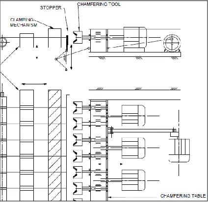
Multi Head Splitter Gear-Box Has been designed with a specific use for chamfering of bar/rebar in mass production system, This Splitter gear box can be multi purposely used in various cutting operation such as drilling, chamfering, turning, etc. A proposed Multi Head Chamfering Machine is as shown in Figure 1. The lot of 3 bars will be held in a clamping mechanism so as to perform the chamfering process with the help of Multi Head chamfering machine. The chamfering machine head will move forward so as to chamfer the positioned rebar. After the chamfering, the cutting head will move backward to its original position. Meanwhile, this paper presents the method used in analyzing the power, torques and forces transmitted through the various gear sets of the Multi Head Chamfering Machine. The chamfering operation is to be performed on the rebar ranging from ϕ8mm to ϕ25 mm. Analysis of forces requires an understanding of the dynamic properties of the systems components. In precision machines in which a definite velocity ratio is of importance, the only positive drive is by means of gears or toothed wheels. Among the various types of gears, helical gear reduces noise and vibration at the same time transfers the required torque smoothly.
Figure 1: A proposed Layout of Multi Head Chamfering Machine.
1. ESTIMATION OF POWER AND TORQUE REQUIREMENT
Available Online at www.ijpret.com 50
design. The prediction of cutting forces, torque, power, and cutting constants are important in sizing machine tools for a particular operation or for selecting cutting speeds, feeds and depth of cuts to avoid tool breakage and chatter vibrations. Considering chamfering process is as turning process.
2.1 Calculation of Power
Figure 2: FBD of Cutting Force.
Where,
Ft = Tangential Force,
Fr = Radial Force,
Ff = Feed Force.
Power (Pc) [2] predicted by
-- (1)
Where,
Pc = Net power requirement (kW)
kc = Specific cutting force (N/mm2)
= 2280 N/mm2
V c = Cutting speed (m/min) = 25 m/min.
ap = Depth of cutting (mm) = 2 mm.
Available Online at www.ijpret.com 51
From the above calculation, required power for single rebar to chamfer is as follows.
Pc= 1.14 KW ~1.5 KW
=2 Hp. -- (2)
Required Machine Power for three rebars,
P = 7.5 Hp = 5.5 KW. -- (3)
We know that the required input torque on motor shaft rotating at 600 rpm.
-- (4)
T=87.57 Nm -- (5)
We have found out a Standard Geared Motor (S1 Series S501_2.4 S4M4sa4—catalogue – Bonfiglioly Motors Helical Gearboxes- Geared Motors S series) which delivers T= 86 Nm Torque at 598 rpm.
We require cutter speed of 300 rpm for the chamfering process. We have devised a splitter Gearbox which converts single input into three outputs. This delivers output torque 57 Nm.
2. DESIGN OF GEAR TRAIN
Proposed gear train for splitter gear box is as shown in following figure.
P1= Input Pinion Gear for Gearbox (Right handed).
P2 = Intermediate Gear between Gear G2 and G3 (Right handed).
G1, G2, G3 = Output Gear of Gearbox (Left handed).
Available Online at www.ijpret.com 52
3. GEAR CALCULATION
According to required input power, Helical Gear calculation, [4] we have designed gears as given
below,
Input Power = 5.5 KW
Pinion material = SAE 4640 (378 BHN)
Gear Material = SAE 4620 (256 BHN)
No. of Teeth on pinion (Tp) =20
Rpm of Pinion (Np) = 600 rpm
No. of Teeth on Gear (Tg) b=36
Rpm of Gear (Ng) = 300 rpm,
Pressure Angle (ф) = 200.
Helix Angle (Ψ) = 200.
Service Factor (Ka) = 1.25.
Load Distribution Factor (Km) = 1.4
Factor of Safety = 1.5
Face Width (b) = 60mm.
Module (m) = 4.
Diameter of Pinion PCD (Dp) = 85.13 mm.
Diameter of Gear PCD (Dg) = 153.24 mm.
4. SHAFT DESIGN
Available Online at www.ijpret.com 53
According to ASME code [4] the permissible shear stress or
(whichever is minimum). If keyway is present, the above values are to be reduced by 25%.
The ASME code is based on Maximum Shear Stress Theory of Failure,
- (6)
From above equations, we got shaft diameter of ϕ40 mm for Pinion Gear P1, P2 & shaft diameter of ϕ25 mm for Gear G1, G2 and G3.
Figure 4: FBD of Gears.
Figure 5: FBD of Shaft of Gear P1.
Figure 6: FBD of Shaft of Gears G2.
5. BEARING SELECTION
Available Online at www.ijpret.com 54
gear drives with small and medium loads and speed. [4] Deep groove ball bearings are mostly
used because they can take both radial and axial loads. By considering rated bearing life (L10h)
10000 hr, we have selected bearing of SKF Bearing No. 16005 for shaft of ϕ25 mm and Bearing No.6308 for shaft of ϕ40 mm.
6. DESIGN OF CUTTER
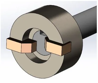
Figure 7: CAD Model of Cutter.
Chamfering Cutter is type of End Finishing Tool. End Finishing tools are technically a special type of milling tool that are normally used to manufacture turned parts. The tool rotates and the work-piece remains stationary. The various arranged cutting plate holders form a contour which is transferred to the work-piece by machine. A variety of work-piece diameters can be machined with the same tool as this can be radially adjustable.
7. DESIGN OF HOUSING
Housing is one of the important elements of machine tool structure. Housing may be split or solid. Solid housings are used in small and medium sized machine tools. Split housings are easier to assemble but stiffness is less as compared to solid one. Split housings are provided with a hinged cover to facilitate its opening. The stiffness of such housing is less than solid housing by 50 %. Housing type structures are designed for stiffness.
8.1 Material of Gearbox Housing
Available Online at www.ijpret.com 55
From above property of materials, housings is fabricated [3] closed box and we have selected
SAE 1020 plates of thickness 20mm
Table 1 Mechanical Property of Housing Materials
Material Sy(MPa) / *Su (MPa) E (MPa) Property R ol le d P lat
e SAE 1020 annealed 250 2.00 x 10
5 ----
SAE 4130 normalized 490 2.00 x 10⁵
----
Cast steel 240-260 1.70 x 10⁵ Good damping, noise reduction.
C
asti
ng
Gray iron *170-250 (0.9-1) x 105 High compressive strength, fatigue resistance and
wear resistance.
High-duty cast iron *320-370 1.70 x 10⁵
Aluminium alloys *150-180 0.72 x 10⁵
Figure 8: Open View of CAD Model of Splitter Gear-Box with Geared Motor.
8. CONCLUSION
With the view to design splitter gear box, we have gone through various mechanical design aspects, in this we have designed the gear, shafts, and housing and also the selection of the bearings is done according to the required load torque and other forces.
REFERENCE
1. Bajirao H. NangarePatil, Prof. P. R. Sawant, “Design And Development Of Gearbox For Multi-Spindle Drilling Machine”, IJERT ,ISSN: 2278-0181, Vol. 2 Issue 5, May – 2013
Available Online at www.ijpret.com 56
3. Joshi P. H., "Machine Tools Handbook Design and Operation", Tata McGraw-Hill Publishing Co. Ltd, New Delhi.
4. Bhandari V. B., “Design of Machine Element”, McGraw-Hill Education (India) Private Limited, New Delhi.