Available Online at www.ijpret.com 508
INTERNATIONAL JOURNAL OF PURE AND
APPLIED RESEARCH IN ENGINEERING
AND TECHNOLOGY
A PATH FOR HORIZING YOUR INNOVATIVE WORK
COMPENSATION OF SAGS AND SWELLS VOLTAGE USING DYNAMIC VOLTAGE
RESTORER (DVR)
PARAG S DESAI,NILESH BORKAR
Electrical & Electronics Dept., Goa College of Engineering, Farmagudi, Ponda, Goa, India- 403401.
Accepted Date: 15/03/2016; Published Date: 01/05/2016
\
Abstract- Modern power system suffers through various power quality issues like voltage sag, swells, frequency droop etc. There are various ways of counteracting this power quality issues using active or passive methods. The Dynamic voltage restorer (DVR) is a dynamic solution to protect sensitive loads against voltage sags and swells. The DVR can be implemented to protect a group of medium voltage or low voltage consumers. The new configuration of DVR has been proposed using improved d-q-0 controller technique.This study is carried out for compensation of sags and swells voltage during single line to ground (SLG) fault, line to line fault (L-L), three-phase fault .And voltage swell, which can cause due to overcompensation in line. Simulation results carried out by Matlab/Simulink .verify the performance of the proposed method
Keywords:- Voltage source converter (VSC), Dynamic voltage restorer (DVR), Power quality (PQ), Synchronous reference frame controller (SRFC), proportional integral controller (PIC).
Corresponding Author: MR. PARAG S. DESAI Access Online On:
www.ijpret.com
How to Cite This Article:
Available Online at www.ijpret.com 509
INTRODUCTION
As we know, quality of the power is facing a various problems such as voltage sags/swells, surge, flicker, voltage imbalance, interruptions and harmonic distortion etc. One of the most essential custom power devices that have been created to improve the performance of power quality is Dynamic Voltage Restorer (DVR). The DVR maintains the load voltage at a nominal magnitude and phase by reimbursing the voltage sag/swell and voltage unbalance at the point of common coupling (PCC). [1][4]Voltage sags/swells caused by unsymmetrical line-to-line, single line-to-ground (SLG), double line-to-ground and symmetrical three phase faults/overcompensation. Voltage sags can occur at any instant of time, with amplitudes ranging from 10-90% and a duration lasting for half a cycle to one minute. Voltage swell, is defined as an increase in RMS voltage for durations from 0.5 cycles to 1 minute. IEEE 519 1992 and IEEE 1159-1995 explain the voltage sags/swells as shown in Figure 1. [3][6]
Figure 1: Voltage reduction standard of IEEE 1159-1995topology
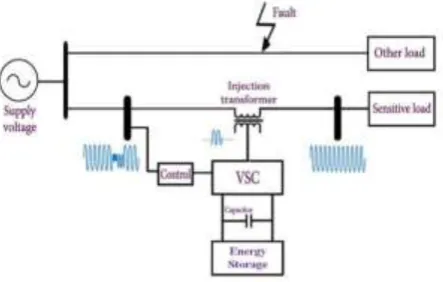
II. STRUCTURE AND OPERATION OF DVR
Available Online at www.ijpret.com 510
Figure 2: The Basic DVR topology
A. Injection Transformer
Injection transformer is used to connect the DVR to the distribution line via High Voltage winding and injects the compensating voltage generated by VSC.
B. Voltage Source Converter (VSC)
VSC is a power electronic device used to generate the compensating voltage. Output voltage of VSC should be balanced and pure sine wave.
C. Harmonic filterHarmonic filter is used to filter the high frequency component from the
output voltage of inverter.
D. Storage device
It is dc storage which is used to supply the necessary energy to VSC to generate the compensating voltage
E. Control circuit
Control circuit continuously observes the supply voltage. It detects the disturbance in the supply voltage, compare it with the set reference value and generate the switching pulses to the VSC to generate the DVR output voltages, which is than given to the transformer. [6]
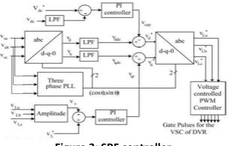
III. SRF CONTROLLER
SRF theory is nothing but the synchronous reference frame theory which is used to generate the reference voltage required to compensate the voltage sag/swell. SRF technique converts coordinates from a-b-c stationary coordinate system to o-d-q rotating coordinate system. Than Signals are converted in o-d-q frame because it is easy to control and process on signals in d-q frame. Then again these signals are converted in a-b-c coordinate system. In this transformation there are four main process of transformation which are described below.[5]
i. Clark’s Transformation
Available Online at www.ijpret.com 511
[𝑉𝑠𝛼
𝑉𝑠] = √
2 3[
1 −1
2 − 1 2 0 √3 2 − √3 2 ] [ 𝑉𝑠𝑎 𝑉𝑠𝑏 𝑉𝑠𝑐
] (1)
ii. Park’s Transformation
After Clark’s transformation this signal is converted in rotating o-d-q frame by using equation (2). [𝑉𝑑 𝑉𝑞] = [ 𝑐𝑜𝑠 𝑠𝑖𝑛 −𝑠𝑖𝑛 𝑐𝑜𝑠] [ 𝑉𝑠𝛼
𝑉𝑠 ] (2)
For above, transformation θ is obtained from phase lock loop (PLL) block. PLL maintains the angle and frequency of the single during entire transformation process. Vd and Vq comprises of both dc and ac component. That is why low pass filter is used to filter out the ac component such that only dc component will be used for further transformation.
Now sagged voltage in d-q frame is subtracted from set reference voltage which is constant voltage in d-q frame and which gives the compensating voltage in d-q frame. Than after by applying inverse Park’s and Clark’s Transformation respectively signal is transformed in a-b-c a-b-coordinates form as
iii. Reverse Park’s Transformation
[𝑉𝑠𝛼 ∗ 𝑉𝑠𝛽∗] = [ 𝑐𝑜𝑠 𝑠𝑖𝑛 −𝑠𝑖𝑛 𝑐𝑜𝑠] [ 𝑉𝑑𝑑𝑐
0 ] (3)
iv. Reverse Clark’s Transformation
[
𝑉𝑠𝑎∗
𝑉𝑠𝑏∗
𝑉𝑠𝑐∗
] = √2
3
[
1
√2 1 0
1 √2 − 1 2 √3 2 1 √2 − 1 2 − √3 2] [ 𝑉𝑠0∗ 𝑉𝑠𝛼∗ 𝑉𝑠𝛽∗
] (4)
𝑽𝒔𝒂∗, 𝑽𝒔𝒃∗𝒂𝒏𝒅 𝑽𝒔𝒄∗
Are the reference source voltages. In below figure3 is the block diagram of SRF controller.
Available Online at www.ijpret.com 512 Figure 3 shows the control block of the DVR system in which the synchronous reference frame (SRF) method is used. The voltages at B2 bus are converted to the rotating reference frame using the abc - dqo conversion using the Park's transformation. And the load voltage is sensed from B3 bus, which is compared with the reference magnitude and then processed through the PI controller. On the other hand the measured Vdc is compared with reference Vdc and then processed through PI controller. Filters are used to remove ac component while transformation. Both the filter outputted are summed and minuses in the d-axis and q-axis respectively such that d-axis will become 1 and q-axis will become zero. Than after this process the signal is brought to its original form by reverse parks and Clarks transformation. [2]
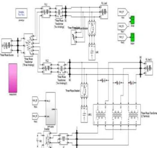
IV. IMPLEMENTATION
Figure 4: The Distribution Model with DVR system along with Sag faults and Overcompensation
In above figure 4, the distribution line is simulated in matlab. The primary distribution line is of 33kv to11 kv, and secondary distribution line is of 11kv to 400v. Here there are two branches on secondary distribution. If we create fault or overcompensation on branch1 the branch 2 will also get affected. So as to eliminate the fault on branch 2, Dynamic voltage restorer is placed as shown in above figure 4. [7]
SYSTEM PARAMETERS
AC line voltage: 415 V, 50 Hz.
Line Impedance: Rs=0.01 Ω, Ls= 3.0 mH Loads: Linear: 10 kVA, 0.80 pf lag DC voltage of DVR: 300 V
AC inductor: 2.0 mH
Available Online at www.ijpret.com 513 AC PI controller: Kp2 =0.1, Ki2 =0. 5
PWM switching frequency: 10 kHz
Series Transformer: Three-phase transformer of rating 10kVA, 200V/300V
V. SIMULATION RESULTS
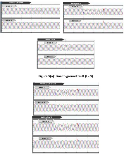
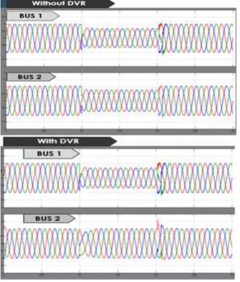
Figure 5(a): Line to ground fault (L- G)
Available Online at www.ijpret.com 514
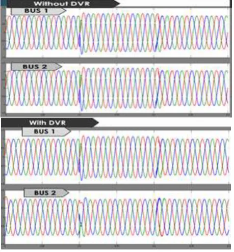
Figure 5(c): Double Line to ground fault (L- L-G)
Figure 5(d): Three phase fault
Available Online at www.ijpret.com 515
Figure 6(a): Single phase voltage swell
Available Online at www.ijpret.com 516
Figure 6(c): Three phase voltage swell
Figure 6: Swell effect due to overcompensation without DVR and with DVR on branch 1 and branch 2 of distribution line.
VI. DISCUSSION
1. Figure 5(a) shows Line to ground fault (L- G).here when L-G fault when created on bus1 the bus2 voltage is also gets affected and R phase magnitude decreases, so as to compensate for R phase DVR is connected in the system and fault is cleared on bus 2 which is shown in with DVR bus 2 waveforms.
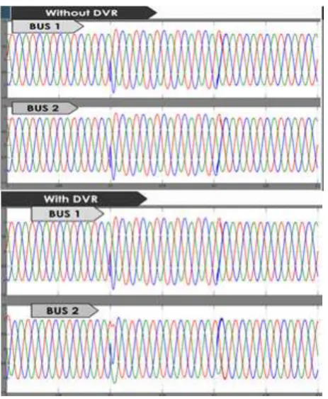
2. Figure 5(b) shows Line to Line fault (L-L), here when sag occurs R and B phase are affected. B is more affected compared to A phase.so by connecting DVR on bus2 the R and B phase compensation is done.
3. Figure 5(c) shows double line to ground fault, here R and B phase are affected again with respect to ground, than again DVR is connected on bus 2 to compensate the fault.
4. Figure 5(d) shows three phase fault and here all phases go in sag condition. To compensate for same DVR is connected.
Available Online at www.ijpret.com 517 6. Figure 6(b) and 6(c) similarly shows the swell effect to two phases and three phases respectively. Here the capacitor bank is connected to two as well as three phases. When the DVR is connected to bus 2 during both two phase and three phase swell conditions the swell affect is absorbed by DVR to bring the voltage back to nominal value.
VII. CONCLUSION
This work has presented the power quality problems such as voltage sags, swells, distortions and harmonics. Voltage sag has been eliminated for different fault conditions such as line to ground fault, line to line fault, double line to ground fault and three phase faults, as well as overcompensation elimination for single, double and three phase swells. Compensation techniques of custom power electronic devices DVR was presented. In this DVR the Vabc to dq technique has been used.A PWM-based control scheme was implemented by MATLAB/ SIMULINK.
REFERENCES
1. Math H.J. Bollen, Understanding Power Quality Problems- Voltage Sags and
Interruptions, IEEE Press, New, 2000.
2. Jayaprakash,control of reduced rating DVR with a battery energy storage system, IEEE
March/April 2014.
3. R. C. Dugan, M. F. McGranaghan and H. W. Beaty, Electric Power Systems Quality. 2nd
Edition, New York, 2006.
4. Antonio Moreno-Munoz, Power Quality: Mitigation Technologies in , Distributed
Environment, Springer-Verlag London limited, London 2007.
5. Abrarkhan I. Pathan,”Different Control Techniques of Dynamic Voltage Restorer for
Power Quality Problems”IEEE Feb 2014
6. D. Nazarpour, “Compensation of Sags and Swells Voltage using Dynamic Voltage Restorer
(DVR) During Single Line To Ground and Three -Phase Faults” IJTPE Journal, September 2012.
![Figure 1. [3][6]](https://thumb-us.123doks.com/thumbv2/123dok_us/8717131.1742761/2.595.172.423.287.435/figure.webp)