Scalable Computing: Practice and Experience
Volume 14, Number 4, pp. 235–247. http://www.scpe.org
ISSN 1895-1767 c
2013 SCPE
TOWARDS AN AUTOMATED BPEL-BASED SAAS PROVISIONING SUPPORT FOR OPENSTACK IAAS
PAOLO BELLAVISTA †, ANTONIO CORRADI †, LUCA FOSCHINI †, AND ALESSANDRO PERNAFINI ‡
Abstract. Software as a Service (SaaS) applications fully exploit the potential of elastic Cloud computing Infrastructure as a Service (IaaS) platforms by enabling new highly dynamic Cloud provisioning scenarios where application providers could decide to change the placement of IT service components at runtime, such as moving computational resources close to storage so to improve SaaS responsiveness. Moreover, emergent Internet of Things (IoT) scenarios enable novel computing applications involving several heterogeneous smart objects interacting with each other. These highly dynamic scenarios call for novel Cloud support infrastructures able to automate the whole SaaS provisioning cycle spanning from resource management to dynamic IT service components placement, including software deployment, components re-activation, and rebinding operations. However, notwithstanding the core importance of these functions to truly enable the deployment of complex SaaS over IaaS environments, at the current stage only partial and ad-hoc solutions are available. This paper presents a support infrastructure aimed to facilitate the composition of heterogeneous resources, such as single Virtual Machines (VMs), DB services and storage, and stand-alone services, by automating the provisioning of complex SaaS applications over the widely diffused real-world open-source OpenStack IaaS. Collected experimental results show the effectiveness of parallel execution of deployment steps introduced by our solution and demonstrate its applicability and advantages in a real SaaS production testbed.
Key words: Cloud computing; Internet of Things; Service orchestration; OpenStack; Juju; BPEL
1. Introduction. Novel Cloud computing infrastructures consisting of worldwide fully interconnected data centers offering their computational resources as IaaS on a pay-per-use basis are opening brand new challenges and opportunities to develop novel SaaS-based applications. Moreover, during the last decade, we experienced the emergency of IoT application scenarios, where heterogeneous and ubiquitous devices, spanning from fully-fledged smartphones to wired and wireless sensors, can interact with each other and cooperate to achieve common goals of enabling new smart scenarios. The unique requirements of IoT environments (such as fast deployability, high scalability, and large-scale provisioning), together with their highly dynamic nature, call for the development of a large number of new SaaS applications exploiting the elasticity offered by novel Cloud systems. These systems are typically characterized by both agile and continuous developments and deployments as well as ever-changing service loads, and call for highly novel automatic solutions able to dynamically and continuously supervise and facilitate the whole application management lifecycle.
In recent years, the advent of new Platform as a Service (PaaS) environments, such as CloudBees, Cloud-Foundry, and OpenShift has simplified the provisioning of new SaaS applications over physical and IaaS-based Cloud systems [1, 2, 3]; at the same time, PaaS technologies tend to impose to the final developer fixed and well-defined software stacks (including languages and usable services), often difficult to modify and to tailor to the specific service needs. In addition, from a more technological perspective, while SaaS and IaaS solutions have been widely used and employed in the last decade even before the advent of the Cloud wave, PaaS represents a younger technology that still deserves much work to improve flexibility and interoperability between different PaaS environments, as well as in enhancing integration opportunities with other existing IaaS and SaaS ones. Focusing only on SaaS-over-IaaS solutions, enabling the management and especially the provisioning of complex SaaS applications over highly dynamic and large-scale Cloud-based IoT environments is still a difficult task that requires to solve several open management issues spanning from virtualization issues, such as Virtual Machine (VM), storage, and network virtualization, to large-scale Cloud monitoring, from optimal resource placement computation to standardization and interoperability of the different deployment frameworks and Application Programming Interfaces (APIs) adopted by various Cloud providers, and so forth.
Among all these challenging issues, the purpose of this paper is to present an architecture that offers a support for the orchestration of all the steps needed to publish a SaaS application within a Cloud IaaS. A
SaaS application inside a Cloud environment can be viewed as a collection of opportunely configured service components deployed into a set of dynamically created IaaS resources. In modern datacenters, there is a high
†Dipartimento di Informatica Scienza e Ingegneria (DISI), Bologna, Italy ({paolo.bellavista,antonio.corradi,luca.foschini}@unibo.it).
‡Centro Interdipartimentale di Ricerca Industriale ICT (CIRI ICT), Bologna, Italy ([email protected]).
availability of computational, storage, and network resources, but it is still missing a mechanism to automatically orchestrate all the involved entities to allocate resources, to deploy and configure various software components, and to manage their interactions in order to provide the requested application. Indeed, before application providers can provide an application, they need to manually perform a set of operations (i.e., request new VMs, install and configure software) that, especially for large-scale deployments, like the ones we could obtain in IoT scenarios, could be really time consuming thus reducing the advantages of having flexible compute infrastructures.
This specific problem has already been partially addressed by some contributions in the literature; however, most of the existing efforts focus on single aspects. For instance, some proposal addressed deployment and life-cycle management of service components [4, 5, 6], while the integration of software lifelife-cycle management as a core function of IaaS environment management supports, instead, apart a few specific seminal studies [7, 8, 10], is still widely unexplored. In this context, we claim the necessity of new fully-integrated automated SaaS provisioning facilities that start from the management of virtual resources, pass through the installation, con-figuration and management of software components, and end with the coordination of these components. That would be highly beneficial both for SaaS application providers, especially in highly dynamic IoT environments, to ease the realization of new SaaS applications through the composition of existing single service components in a mash-up like fashion, and for IaaS Cloud providers, by taking over all the error-prone and time-consuming deployment and configuration operations at the IaaS level.
To address all these open issues, this paper proposes a novel automated SaaS-over-IaaS provisioning support that adopts three main original guidelines. First, it provides to both IaaS Cloud providers and to SaaS appli-cation providers a tool that transparently takes over the execution of software deployments and updates with almost no need for human intervention. Second, it proposes a general automated application provision support that integrates with state-of-the-art technologies, such as the highly interoperable OpenStack IaaS and the standard Business Process Execution Language (BPEL), to ease the definition of all main deployment, config-uration, and deployment monitoring steps. Third, our prototype has been implemented as an open-source tool based on the open-source OpenStack Cloud platform and is made available to the Cloud community. Finally, in order to better underline the benefits and original aspects of the proposed solution and to demonstrate the effectiveness of our solution, the paper presents an experimental evaluation based on a realistic SaaS application provisioning scenario on top of an open-source testbed based on OpenStack.
The remainder of this paper is organized as follows. In Sect. 2, we give an overview of related work in the literature. In Sect. 3, we introduce needed background material about all main involved standards, technologies, and support tools; in Sect. 4, we present our framework and outline its main components; in Sect. 5, we provide some implementation details about our presented architecture. Finally, in Sect. 6 we show collected experimental results. Conclusions and directions of future work end the paper.
2. Related works. The on-demand provisioning of services and resources in distributed architectures has been deeply investigated in recent years. For the sake of space limitations, we will focus on two research directions only: we start with works that provide solutions for the deployment and lifecycle management of software components; then we move towards solutions that, closer to our proposal, enable automated provisioning of applications by integrating software lifecycle as part of the wider Cloud IaaS management operations.
Focusing on the first research direction, the design, deployment, and management of software components can be challenging in systems distributed on a large scale, and several different systems provide solutions to automate these processes. The work depicted in [4] presents a system management framework that, given a model of configuration and lifecycle, automatically builds a distributed system. Similarly, authors of [5] introduce a model-based solution to automatically configure system specifications and provide this system on-demand to the user. Finally, in [6], authors presented a solution to face change management issues; this solution aims to automate all the steps required to handle software or hardware changes to existing IT infrastructures, with the goal of an high degree of parallelism. All these solutions provide the automation of the deployment and management of software components, so relieving administrator of the burden of manually configure distributed systems; however, they only focus on the deployment of software components and do not consider virtual infrastructure management, that instead assumes a central role in Cloud environments.
of applications in Cloud systems. The solution presented in [7] describes a multi-layer architecture that enables the automated provisioning and management of cloud services; with this solution users can select a service from a catalog of service templates, then the service can be configured by the user and deployed automatically. Authors of [8] present a solution for on-demand resource provisioning based on BPEL [9]. This solution extends BPEL implementations with the possibility to schedule workflow steps to VMs having a low load and the possibility to add new VMs on-demand in peak-load situations. Both solutions focus on one of the most challenging aspects of Cloud computing, i.e., the capability to request and use computational resources in a small lapse of time, resulting in a fast performance increment and in a decrease of management costs. The works depicted in [10] and [11] propose similar architectures for a generic provisioning infrastructure based on BPEL. These solutions allow SaaS application providers to define generic provisioning workflows independent from the underlying provisioning engines by enabling the possibility to automate the component-to-workflow matching process; they also supports dynamic provisioning flows in order to face peak-load situations by allocating additional resources at runtime. At the same time, these approaches focus more on the theoretical part of the management process and leave out of the scope of the work possible implementation issues and analysis of additional overhead introduced by the proposed solutions. Finally, another very interesting effort, also because complementary to ours, is the one presented in [12] that aims to standardize both topology and orchestration specifications for Cloud applications with a goal to make SaaS applications and their management portable across different IaaS Cloud providers.
3. Background. This section introduces some background knowledge to provide a better understanding of the area. Section 3.1 presents Cloud IaaS environments and provides needed details about the standard-de-facto OpenStack IaaS [13]. Section 3.2 presents Juju, a scripting-based tool to ease the deployment of service components [14]. Finally, Section 3.3 gives some needed background material about the BPEL standard that we use to orchestrate the whole application provisioning process through the definition of proper workflows [9]. Before starting, let us introduce some terminology about the three main types of actors in Cloud systems:
Application users,Application providers, andCloud providers. Application users are the final clients that require access to particular online SaaS application and use its resources. Application providers build and expose SaaS applications, typically composed by several service components, to the end users, and tend to externalize the execution of their own services to avoid the deployment of costly private IT infrastructure. Finally, Cloud providers supply application providers with resources on a pay-per-use fashion, in order to let them execute their applications over their IaaS-based environment. In this paper, we will focus mainly on the application providers and on how they interact with Cloud providers to enable, declare, and monitor the provisioning of complex applications consisting of multiple service components.
3.1. OpenStack. OpenStack is an open-source project for building and managing private and public Cloud infrastructures [13], proposed and promoted by NASA and Rackspace in 2010. OpenStack belongs to the category of Infrastructure as a Service (IaaS) systems, whose goal is to provide resources, such as virtual machines, virtual storage blocks, etc., on-demand from large pools installed in datacenters. OpenStack is based on a very flexible architecture supporting a very large set of hardware devices and hypervisors (i.e. Hyper-V, KVM, ESX, etc.) and even small businesses are allowed to deploy their own private Cloud because of the open-source nature of this solution. However, OpenStack still lacks a monitoring and dynamic reconfiguration mechanism to favor a dynamic deployment of applications on a large scale, thus requiring a manual management to tailor specific scenarios and deployments.
OpenStack manages computation, storage and networking resources on the Cloud in order to provide dynamic allocation of VMs [13]. OpenStack is based on five main services: the first one, called Nova, to manage both computational and networking resources; the second one, named Glance, to manage and provide VMs images; the third one, Neutron to manage network resources, and, finally, Swift and Cinder to manage storage resources. To better understand our work, we provide a more detailed description of Nova service.
migration toward different Cloud providers, OpenStack also supports Amazon EC2 APIs to deploy applications written for Amazon Web Services with a minimal porting effort [15]. In the following, we report several other details about the main Nova services.
Nova-compute service, running on every node in the Cloud, launches and configures VMs within a certain physical host. It communicates with the underlying hypervisor to instantiate and terminate VMs and to obtain load statistics as well as performance metrics of VMs. OpenStack supports a wide range of hypervisors, but the most commonly used hypervisor is KVM, due to its good performance and its full support toward the virtualization of x86 architectures.
Nova-network service manages all the aspects related to network management. This service makes it possible to create virtual networks that allow communications between different instances of VMs. A private IP is assigned to every VM during boot, but it is also possible to assign it a public IP in order to make it accessible over the Internet. All networking functionalities are moving towards the OpenStack service Neutron. This service offers the possibility to create networks that can be associated to different tenants; it is also possible to create virtual routers to enable communication between two or more VMs belonging to different tenant networks. Thus, networks can be seen as resources available in the Cloud and Neutron can be considered as a Network as a Service (NaaS).
Finally, nova-scheduler service determines on which node a VM should be booted. Actually this service offers only a small set of simple scheduling policies, such as selecting the least loaded host or randomly selecting a host. Even if OpenStack offers a scheduler mechanism to choose where a VM should be booted, it does not provide any dynamic mechanism to migrate running VMs based on the current host load.
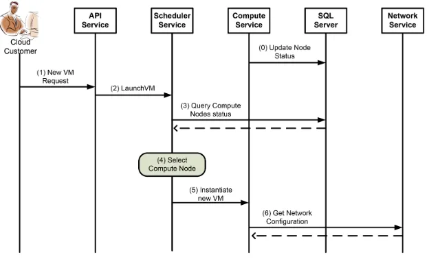
To show the interactions between OpenStack services, we introduce a simple VM instantiation use case (see Fig. 3.1). The current state of the entire Cloud is maintained in a SQL server; periodically each nova-compute service running on a certain node updates the SQL server with load information about that node (step 0). When a user requests the instantiation of a new VM through the RESTful APIs (step 1), the nova-api service sends a request to the nova-scheduler service (step 2) to determine on which host the new VM should be launched. In this step, the scheduler queries the database in order to obtain a list of available hosts along with their load information (step 3), and then selects one of them (step 4) according to the chosen policy. Finally, the scheduler sends a VM instantiation request to the nova-compute service running on the selected node (step 5) that requests network configuration parameters to the network service (step 6).
Fig. 3.1.VM instantiation in OpenStack
Juju focuses on the management and deployment of various service units and components needed to provide a single application, by taking over the configuration and installation of required software on the VMs where these service components will be deployed. Juju allows independent service components to communicate through a simple configuration protocol. End-users can deploy these service components inside the Cloud, in a similar way they can install a set of packets with a single command. As a result, it is possible to obtain an environment consisting of multiple machines whose service components cooperate to provide the requested application.
Juju is independent from the underlying Cloud Infrastructure Layer and supports several Cloud providers such as OpenStack, Amazon Web Services, HP Cloud, Rackspace, etc. Thus, it is possible to migrate a service component between different Clouds with minimal re-deploy effort.
A service component represents an application or a group of applications integrated as a single component inside a Juju environment that can be used by other components in order to build an higher level application. In this paper we consider the use case where we provide WordPress, an open-source platform to create, manage, and create dynamic Web site [16], by configuring and orchestrating two distinct service components: a service component exposing the MySQL database needed by WordPress, and another service component running the WordPress engine. A service component instance is called Service Unit and it is possible to add more of these Service Units to the environment in order to scale the whole system, thus reducing the load on each VM.
Three main concepts are at the basis of services publication: charms, hooks andrelations.
Acharm encapsulates the logic required to publish and manage a service component inside a Juju environ-ment. A charm provides the definition of a service component, including its metadata, its dependences on other service components, the software packets we need to install in a VM, along with the logic needed to manage the service component. Through the definition of a charm, it is possible to define the functionalities exposed by the service component and, if we are dealing with a composed service, all the sub-services required.
Hooks are executable files used by Juju to notify a service component about changes related to its lifecycle or about other events happened inside the environment. When a hook is executed, it can modify the underlying VM (i.e. it could install new software packets) or it can change relations between two or more service components. Finally, relations allow the communication between different service components. Relations are defined inside a charm to declare the interfaces needed/exposed by a service component, that are offered/used by another service component. Low level communications between service components are based on TCP sockets. Theenvironment is a fundamental concept at the basis of Juju: it can be seen as a container where service components can be published; environments are managed through a configuration file where it is possible to define some configuration parameters such as used Cloud provider, IP address of the Cloud provider, authenti-cation credentials, etc.
It is possible to execute an environment through the bootstrap operation exposed by Jujus API. The bootstrap operation initialize the system, instantiating a VM that will act as the controller node of the envi-ronment. Zookeeper and Provisioning Agent are two of the main software components executed on controller node. Zookeeper can be viewed as a file systems that stores all the information about the environment, while Provisioning Agent interacts with the underlying Cloud provider in order to instantiate and terminate VMs where service components are going to be deployed.
3.3. BPEL. BPEL is the de facto standard to define business processes and business interaction protocols [9]. The BPEL language, based on XML, allows to express the orchestration of multiple Web Services by defining business interactions modeled after a sequence of message exchanges between involved entities. A BPEL document contains the control logic required to coordinate all the Web Services involved in a workflow. BPEL provides many language constructs and mechanisms to define a sequence of activities like invoke,
receiveandreply, parallel and sequential execution, transactional execution of a group of activities, and exception handling. A partnerLink is an important construct defined by BPEL to represent an external service that is invoked by a process or that invokes the process itself.
4. Architecture. This section presents our architecture proposal to face all the main service orchestration challenges described in the previous sections: the proposed architecture provides the support to orchestrate all the steps involved in the publication of an application inside a Cloud platform, starting from the instantiation of required VMs to the deployment of required software components, together with the definition of their relationships. First, we briefly introduce this architecture and then we give a more in deep description of its components.
The proposed architecture is easily extensible, due to its multi-layer nature; it allows to arbitrarily manage the software components that form an application, and to use several Cloud providers. Starting from requests asking for application provisioning sent from application providers, it is possible to automatically satisfy their requests by monitoring all the steps involved in the application publication and notifying application providers about the progress of their request.
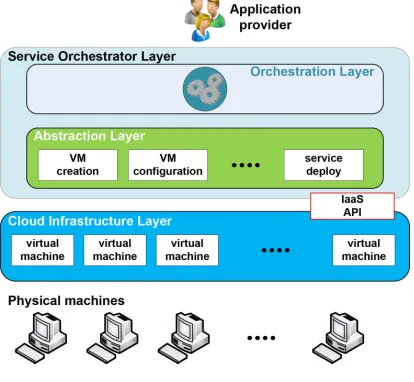
The proposed architecture (see Fig. 4.1) consists of aCloud Infrastructure Layer and aService Orchestrator Layer that, in its turn, we logically divided in two sub-layers: anAbstraction Layer and anOrchestration Layer.
Fig. 4.1.Proposed architecture
The Cloud Infrastructure Layer represents the virtual resources provided by the Cloud infrastructure through the IaaS API: it contains VMs instances and defines the APIs required to create, configure and destroy VMs used by upper layers; it also offers a connection mechanism in order to grant access to VMs. In our im-plementation, we choose to use OpenStack as Cloud Infrastructure Layer, as it is a widely adopted open-source solution; at the same time, thanks to the highly flexible nature of our architecture, it is possible to use any other Cloud provider.
The Orchestration Layer and the Abstraction Layer compose together the Service Orchestrator Layer. It is the composition of these two layers that makes it possible to create an orchestration support. Once the application provider has sent a request, this layer will coordinate and execute all the activities to satisfy that request, by opportunely configuring and communicating with the VMs provided by the Cloud Infrastructure Layer.
by the web server. To deploy this scenario, the Abstraction Layer will create two VMs (one for the web server and the other one for the database), install all the required software packages, and configure and start the two services. However, in order to publish a working web server, these services need to communicate to each other. This can be done by defining a relationship between the two services and specifying the functionalities exposed by each service along with the required functionalities. It is essential that the Abstraction Layer could access the VMs where the two services are deployed in order to monitor and, possibly, reconfigure the services; this is achieved by establishing SSH tunnels to VMs.
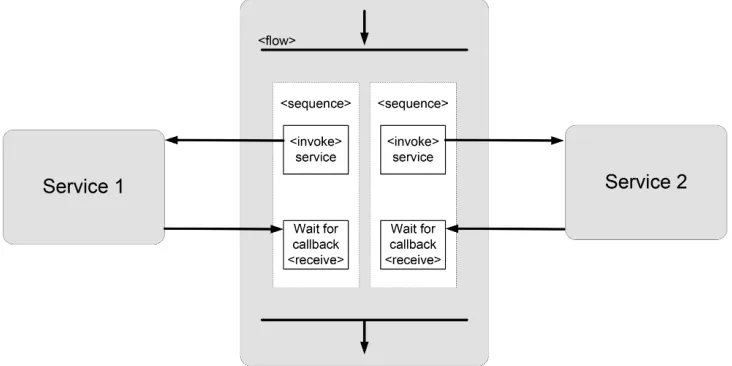
The Orchestration Layer represents the orchestration engine inside our architecture. When an application provider submits a request to this layer, it coordinates and orchestrates all the steps required to automatically provide the application provider with the requested application. Every request received by the Orchestration Layer contains a description of the required application, that can be seen as a model defining the service components that compose the application, along with the description of their relationships to determine how they must mutually interact. Typically, many activities are involved in exposing an application, so this layer needs to manage transitions between these activities, by taking into account the dependencies between service components as shown in Fig. 4.2. These dependencies represent the synchronization points between operation sequences executed inside a workflow.
Fig. 4.2.Typical Orchestration Layer workflow
Going back to our previous example, it is impossible to publish a web server before the database is ready, because it would lack the required support to manage data. When the database is ready and the web server has been deployed, we can specify the relationship between these two software components. The Service Orchestrator Layer deploys those service components in parallel, monitoring the involved steps; that allows to simultaneously deploy several service components. In our solution, we implement this layer by using a BPEL engine.
of our support towards services orchestration: this layer makes it possible to coordinate the publication of SaaS applications, defining reusable and modular workflows.
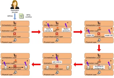
Fig. 5.1 shows how the architecture layers interact with each others in order to provide a generic application composed by two different service components. Starting from a BPEL workflow defined by a Cloud provider, the BPEL engine will send two simultaneous requests to Juju so as to deploy these service components (step 1 in Fig. 5.1). Juju will then ask OpenStack to create two VMs, and, after the VMs have been booted, it will download and install software packets on them (steps 2 and 3). Once the two service components have been configured, the BPEL engine will ask Juju to add a relation between them (step 4); finally, Juju will opportunely configure these components in order to let them cooperate.
Fig. 5.1.Interactions among architecture layers
In particular, we used our Cloud support to implement the case study of a WordPress platform composed by two service components: a MySQL database and a WordPress engine running on a web server, each one deployed on a separate VM. Let us stress that simple services, such as this one and the Wiki service considered in the experimental results, are becoming more and more relevant in IoT scenarios to ease the publication of collected smart data by using Web-enabled and widely accessible data portals and front-ends.
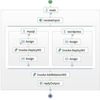
In order to deploy a working WordPress platform, first we need to deploy the database service component and the WordPress engine, and then to add a relation between them to let them cooperate. We mapped all these steps into the BPEL workflow shown in Fig. 5.2.
Fig. 5.2.BPEL workflow
completion of <flow>activity will occur only after both WordPress and MySQL have been deployed. Only at this time, we can invoke AddRelationWS to add a relation between these two service components.
We encapsulated the functionalities exposed by Juju, to deploy and monitor a service component inside the Web Services published on Apache Axis2. The name of the service component that needs to be published is specified inside the request sent to the Web Service. DeployWS is realized by two Java classes: Executor, that invokesjuju deploycommand in order to deploy the service component, and DataMonitor, that manages ZooKeeper events in order to monitor the progress of the request. The following figure shows an excerpt of the WSDL file relative to DeployWS (see Fig. 5.3). AddRelationWS invokes juju add-relationcommand and communicates the result of this operation to the BPEL Engine.
<w s d l : m e s s a g e name=” deployWSRequest”>
<w s d l : p a r t name=” p a r a m e t e r s ” element=” ns:deployWS ”/> </ w s d l : m e s s a g e>
<w s d l : m e s s a g e name=” deployWSResponse”>
<w s d l : p a r t name=” p a r a m e t e r s ” element=” ns:deployWSResponse ” /> </ w s d l : m e s s a g e>
<w s d l : p o r t T y p e name=” DeployWSPortType”> <w s d l : o p e r a t i o n name=”deployWS ”>
<w s d l : i n p u t message=” ns:deployWSRequest ” wsaw:Action=” urn:deployWS ” />
<w s d l : o u t p u t message=” ns:deployWSResponse ” wsaw:Action=” urn:deployWSResponse ” />
</ w s d l : o p e r a t i o n> </ w s d l : p o r t T y p e>
Fig. 5.3.DeployWS WSDL code
configuration file, a reference to the host where MySQL database is running, together with the credentials to access the database. Fig. 5.4 shows an excerpt of the WordPress relation-joined hook used in our tests.
d a t a b a s e =‘ r e l a t i o n−g e t da ta ba se ‘ u s e r =‘ r e l a t i o n−g e t user ‘
password =‘ r e l a t i o n−g e t password ‘ h o s t =‘ r e l a t i o n−g e t p r i v a t e−a d d r e s s ‘
j u j u−l o g ” Wr iting w o r d p r e s s c o n f i g f i l e $ c o n f i g f i l e p a t h ” # Write t h e w o r d p r e s s c o n f i g
c a t > $ c o n f i g i n f o p a t h << EOF <?php
d e f i n e ( ’DB NAME ’ , ’ $ d a t a b a s e ’ ) ; d e f i n e ( ’DB USER ’ , ’ $ u s e r ’ ) ;
d e f i n e ( ’DB PASSWORD’ , ’ $ password ’ ) ; d e f i n e ( ’DB HOST ’ , ’ $ h o s t ’ ) ;
d e f i n e ( ’SECRET KEY ’ , ’ $ s e c r e t k e y ’ ) ; d e f i n e ( ’WP CACHE ’ , t r u e ) ;
Fig. 5.4.Juju hook script
6. Experimental Results. We tested our solution on a Cloud testbed environment at our campus, by considering two different use cases. The first one is more simple and realizes the implementation use case detailed in the previous section, while the second one is more complex and represents a more realistic IoT SaaS application with higher performance requirements.
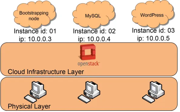
Starting with the first WordPress use case, the physical Cloud testbed consists of 3 physical Linux boxes with Intel Core 2 Duo E7600 at 3.06 GHz and 4 GB RAM, connected through two 1 Gbps LANs, and running Linux Ubuntu 13.04. Fig. 6.1 shows the Cloud infrastructure and the software components deployed on it: this virtual infrastructure consists of 3 VMs running Linux Ubuntu 12.04; Juju bootstrapping node has been deployed on the first VM, while the remaining VMs, were used, respectively, to deploy a MySQL database and a web server running a WordPress engine.
Fig. 6.1. Testbed deployment - first scenario
deploy MySQL and WordPress, and, then, we added a relation between them. Instead, in the second series, we used the Orchestration Layer, in order to achieve a parallel deployment of MySQL and WordPress. All the measures were taken in a stable system, after the deployment of Juju bootstrapping node; we have repeated 30 runs for each test and we report both estimated average and standard deviation.
Fig. 6.2.Deployment time - first scenario
As we can see in Fig. 6.2, thanks to the parallel deployment of MySQL and WordPress, the overall time needed to deploy a working WordPress platform halves the time measured when deploying it sequentially. The average runtime of our tested BPEL process, including the time needed to instantiate a new VM, was about 578.4 seconds, with a standard deviation of 55.3 seconds. Instead, when using sequential Juju commands to deploy the service components, we measured an average runtime of 1138.6 seconds with a standard deviation of 115.8 seconds.
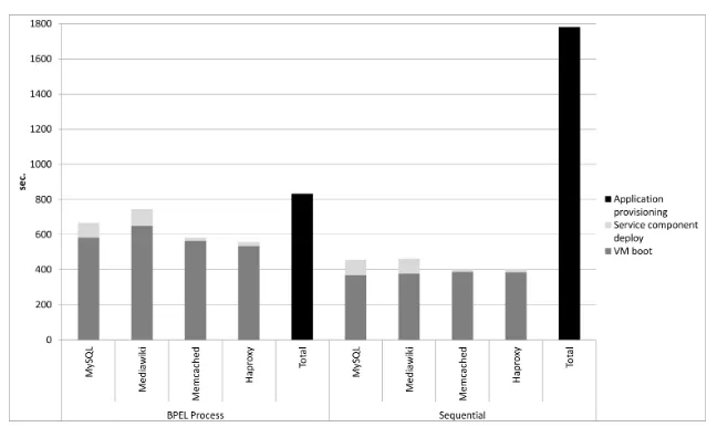
To challenge our support with a more realistic use case, we repeated all the tests described above with a more complex deployment of a multi-tier SaaS application consisting of four different service components: a service component providing a MySQL database; a service component running MediaWiki [19], an open source platform used to create wiki websites such as Wikipedia; a service component running Memcached [20], used to provide MediaWiki with a caching service, and finally a service component running HAProxy [21], an high performance load balancer for TCP/HTTP-based application. Fig. 6.3 shows the Cloud infrastructure and the software components deployed on it: this virtual infrastructure consists of 5 VMs running Linux Ubuntu 12.04; Juju bootstrapping node has been deployed on the first VM, while the remaining VMs, were used, respectively, to deploy a MySQL database, a web server running MediaWiki, a Memcached distributed memory object caching system, and a HAProxy loadbalancer. After deploying these services, three relations are added, respectively between MediaWiki and MySQL, between MediaWiki and Memcached, and between MediaWiki an HAProxy. As shown in Fig. 6.4, the average runtime of our tested BPEL process, including the time needed to instantiate a new VM, was about 832.8 seconds (standard deviation 56.22 seconds) that significantly lowers the average runtime of 1780.8 seconds (standard deviation 119.88 seconds) needed for the sequential deployment.
So, we can conclude that the parallel execution of many processes can balance the overhead introduced by the invocation of Web Services, by the BPEL engine execution, and by execution of multiple deployment operations (potentially concurrent over the same physical host), with the enhanced performance due to parallelism; these advantages are more and more sensible as the complexity of the SaaS application to deploy increases.
Fig. 6.3. Testbed deployment - second scenario
Fig. 6.4.Deployment time - second scenario
status. Moreover, it enables concurrent execution of parallelizable service component deployment steps, thus significantly reducing the time needed to activate complex SaaS applications in large-scale Cloud environments, particularly in IoT scenarios, where the highly dynamic nature of these environments often requires fast ap-plications provisioning. Experimental results showed the effectiveness of the realized support that introduces a limited overhead by granting a drastic reduction of the provisioning time when deployment steps can be executed in parallel. Moreover, the use of BPEL and workflow processes enables a higher degree of flexibility and reusability of our framework; indeed, already existing provisioning workflows can be reused to provide new SaaS applications. Encouraged by these results, we are considering several future directions: on the one hand, we are currently integrating our new application provisioning facilities with our IaaS runtime monitoring and management support [22]; on the other hand, we are developing an automatic application live-migration support to move the whole application, including all needed service components and relations, from local private Cloud IaaS to public ones, by dynamically re-binding all needed virtual resources therein; finally, we are implement-ing a mechanism to define multi-tenant network infrastructures and to provide isolation for multi-tenant SaaS applications deployed atop them.
Acknowledgments. This research was partly funded by CIRI, technology transfer center for ICT, of the University of Bologna; we also thank CINECA for its support.
[1] CloudBeeshome page, http://www.cloudbees.com/. Last accessed: June 2013. [2] CloudFoundryhome page, http://www.cloudfoundry.com/. Last accessed: June 2013. [3] OpenShifthome page, https://openshift.redhat.com/. Last accessed: June 2013.
[4] P. Goldsack et al., The SmartFrog configuration management framework, ACM SIGOPS Operating Systems Review, 43(2009), pp. 16–25.
[5] S. Singhal, M. Arlitt, D. Beyer, S. Graupner, V. Machiraju, J. Pruyne, J. Rolia, et al.,Quartermaster A Resource Utility System, in Proceedings of 9th IFIP/IEEE International Symposium on Integrated Network Management, 2005, pp. 265–278.
[6] A. Keller, J. L. Hellerstein, J. L. Wolf, K. Wu and V. Krishnan,The CHAMPS system: change management with planning and scheduling, in Proceedings of IEEE/IFIP Network Operations and Management Symposium (NOMS 2004), 2004, pp. 395–408.
[7] J. Kirschnick, J. M. Alcaraz Calero and N. Edwards,Toward an architecture for the automated provisioning of cloud services, IEEE Communications Magazine 48 (2010), pp. 124–131.
[8] T. Dornemann, E. Juhnke and B. Freisleben,On-Demand Resource Provisioning for BPEL Workflows Using Amazon’s Elastic Compute Cloud, in Proceedings of 9th IEEE/ACM International Symposium on Cluster Computing and the Grid (CCGRID ’09), 2009, pp. 140–147.
[9] T. Andrews, F. Curbera, H. Dholakia, Y. Goland, J. Klein, F. Leymann, K. Liu, D. Roller, D. Smith,S. Thatte, I. Trickovic and S. Weerawarana,Business Process Execution Language for Web Services Version 1.1. 1.1 Edition. Microsoft, IBM, Siebel, BEA, and SAP (2003).
[10] R. Mietzner and F. Leymann,Towards provisioning the cloud: On the usage of multi-granularity flows and services to realize a unified provisioning infrastructure for saas applications, in: IEEE Congress on Services - Part I, 2008, pp. 3–10. [11] R. Mietzner, T. Unger and F. Leymann,Cafe: A Generic Configurable Customizable Composite Cloud Application
Frame-work, On the Move to Meaningful Internet Systems (OTM 2009), 2009, pp. 357–364.
[12] T. Binz, G. Breiter, F. Leyman, and T. Spatzier, Portable Cloud Services Using TOSCA, IEEE Internet Computing Magazine 16 (2012), pp. 80–85.
[13] OpenStack Cloud Software, http://www.openstack.org/. Last accessed: June 2013. [14] Jujuhomepage, https://juju.ubuntu.com/. Last accessed: December 2013.
[15] Amazon Elastic, Compute Cloud, http://aws.amazon.com/ec2/. Last accessed: June 2013. [16] Wordpress, http://wordpress.org/. Last accessed: July 2013.
[17] Puppet, http://puppetlabs.com/. Last accessed: July 2013. [18] Chef, http://www.opscode.com/chef/. Last accessed: 2013.
[19] MediaWiki, http://www.mediawiki.org/wiki/MediaWiki. Last accessed: December 2013. [20] Memcached, http://memcached.org/. Last accessed: December 2013.
[21] HAProxy, http://haproxy.1wt.eu/. Last accessed: December 2013.
[22] J. Povedano-Molina, L. Foschini, A. Corradi, J. M. Lopez-Vega and J. M. Lopez-Soler,DARGOS: A highly adaptable and scalable monitoring architecture for multi-tenant clouds, Future Generation Computer Systems, 29 (2013), pp. 2041– 2056.
Edited by: Maria Fazio and Nik Bessis
Received: Nov 2, 2013