Available Online at www.ijpret.com 257
INTERNATIONAL JOURNAL OF PURE AND
APPLIED RESEARCH IN ENGINEERING AND
TECHNOLOGY
A PATH FOR HORIZING YOUR INNOVATIVE WORK
DEVELOPMENT OF HARDWARE ABSTRACTION LAYER FOR ENHANCING
SOFTWARE PORTABILITY
MAISIE FERNANDES1, SANGEETA MAHADDALKAR1,MANIKANDAN KUMARAGURU2 1. Electrical & Electronics Dept.,Goa College of Engineering,Farmagudi, Ponda, Goa, India- 403401
2. Research & Development Dept.,Siemens Ltd., Verna Industrial,Estate, Verna,Goa, India- 403722
Accepted Date: 15/03/2016; Published Date: 01/05/2016
\
Abstract:With the growing diversity of Microcontroller platforms it has become tedious to redevelop the software design for every platform. Having portable software will help developers reduce the development time to integrate the software into the hardware. Developing a Hardware Abstraction Layer (HAL) can ensure the software reuse when ported across microcontroller platform having different architecture. The paper proposes the concept of HAL for two underlying Microcontroller platforms (16bit & 32bit architecture) targeting applications to power system protection. The paper discusses how a HAL is developed for the UART module of the two platforms.
Key Words: Hardware Abstraction Layer (HAL), Application Programming Interface (API),
Middleware, UART
Corresponding Author: MS. MAISIE FERNANDES Access Online On:
www.ijpret.com
How to Cite This Article:
Maisie Fernandes, IJPRET, 2016; Volume 4 (9): 257-265
Available Online at www.ijpret.com 258
INTRODUCTION
In embedded systems, software is becoming more and more important than ever before due to its high complexity in the entire system. Much of the development time and effort is spent on integrating the software into the hardware. Time to market is a key issue in the embedded system design process. Lesser time to market ensures capturing the market for the new product launched. However, on account of a change in the hardware architectures of the underlying platform, porting application faces compatibility issues which requires a lot of time and effort in debugging. Software portability and reuse are effective ways to address these issues. This paper proposes a method to achieve software portability across platforms of different architectures.The paper is organized in the following manner: Section II discusses the Architecture of an Embedded System, Section III covers Portable Software Architecture, Section IV discusses the Controllers used for the Implementation, Sections V and VI covers the aspects pertaining to The Hardware Abstraction Layer and the development process. The last section covers conclusion.
II. ARCHITECTURE OF AN EMBEDDED SYSTEM
An understanding of the embedded system architecture can help in embedded systems design and can also resolve the challenges faced when designing a new system.
Most common of these challenges include:
1. Defining and capturing the design of the system 2. Development cost limitations
3. Determining system integrity like reliability and safety.
Without defining or knowing any of the implementation details, the architecture of an embedded system defines the infrastructure of a design, possible design options, and design constraints. The architecture can be used to accurately estimate and reduce costs through its demonstration of the risks involved in implementing the various elements, allowing for the mitigation of the risks [1]. Finally the various structures of architecture can then be leveraged for designing future products with similar characteristic, thus allowing design knowledge to be reused, and leading to a decrease of future design and development cost.
In general, the embedded system architecture is divided into two main layers: 1. Hardware layer
Available Online at www.ijpret.com 259
A. Hardware layer
Various hardware components need to be incorporated to form an embedded system (e.g. peripherals such as UART, timers, ADC etc.)
Major hardware components can be classified as follows: 1. CPU, the master processor
2. Memory, executing the application/storage 3. Input devices, input slave processors 4. Output devices, output slave processors
5. Data pathways/buses, interconnects the other components
B. Software layer
The software layer is divided into the application software and the system software.
The application software layer consists of the application program and the system software supports this application as shown in Figure 1 the system software can have different architecture as:
1) The device driver layer alone can consist of the system software layer.
2) It can consist of a Middleware layer that sits on top of the Device Driver layer. 3) It can have an Operating System layer that sits on top of the Device Driver
Figure 1: Embedded System Architecture [1]
III. PORTABLE SOFTWARE ARCHITECTURE
Available Online at www.ijpret.com 260
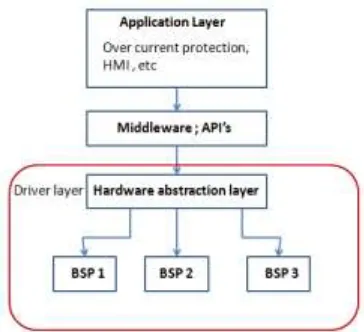
Figure 2 shows the software architecture to achieve platform portability.
Figure 2: Software Architecture
The components are as follows:
1. Application layer:
This layer is independent of the hardware; it is managed and run by the system software. Some considerable applications for power system protection are:
1. Over current protection function 2. MODBUS RTU communication 3. HMI interfacing
A. Middleware layer:
This layer is developed to mediate between the application layer and device driver. It is an API library that provides system abstraction to application software to increase application portability.
B. Driver layer:
This layer consists of the HAL and the Board Support Package (BSP) for each hardware platform.
C. Hardware Abstraction Layer:
Abstraction layer provides the interface between Middleware and the BSP. This layer enables a device driver to interact with a hardware device at a general or abstract level.
D. Board support packages (BSP):
Available Online at www.ijpret.com 261 1. Boot loader support
2. Memory map support 3. Clock system support 4. Interrupt controller support 5. System timer support 6. Power management , etc
Figure 3 shows an illustration of the software architecture for a serial communication application that requires initialization of UART and transmission of data frame.
Figure 3: Illustration of the Software Architecture
Available Online at www.ijpret.com 262 uses uart_init( ) function that is defined in abstraction layer. Based on the underlying platform definition, the APIs in the abstraction layer calls the respective driver/BSP. The hardware dependent routines are then carried out by the BSP.
IV. THE CONTROLLERS USED FOR THE IMPLEMENTATION
The current application targets power system protection. The concept of HAL is developed and configured to target two microcontrollers from Texas Instruments one with Von Neumann architecture and another with Harvard Architecture namely,
1. MSP430F5529 (MSP430F5xx family) 2. MSP432P401R (MSP432P4xx family)
A brief comparison of the two architectures is shown below in Table .
Table 1. Comparison between MSP430F5xx & MSP432P4xx [3] [4]
MCU MSP430F5xx MSP432P4xx
Architecture Von Neumann Harvard
Bus type 16-bit, msp430 bus 32-bit, AHB
Instruction set RISC RISC, Thumb,Thumb2
Pipeline None 3-stage
Clock Frequency 25 MHz up to 48MHz
Flash/ROM 512KB 256KB/32kB
RAM/SRAM 66KB (RAM) 64kB
Digital I/O 59 84
DMA 3 Ch 8 Ch
UART 2 4
I2C 2 4
SPI/SSI 4 8
Power modes Active, LPM0-LPM4,LPMx.5 Active, low freq, LPM0,
LPM3,LPMx.5
Gen purpose timer 4(16-bit) 4(16-bit), 2(32-bit)
Available Online at www.ijpret.com 263
V.THE HARDWARE ABSTRACTION LAYER
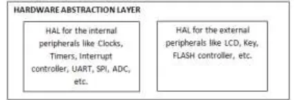
Conceptually the presence of HAL ensures portability of software across different BSP. In an embedded system, there are supporting components around the core which serve different purposes. Examples include, interrupt controller, clock, timers, UART, ADC, SPI, etc. Although implemented in different ways on different hardware platforms, they basically perform the same function. For instance, hardware peripherals like UART or SPI follow a general protocol but they may have different register access methods or buffer size depending on the different Microcontroller platforms. By using HAL we can abstract the hardware component into basic functions and hide the details of the way these functions are implemented from the upper layer of software. Thus HAL interacts with the device in a more general way, providing the developer with a key advantage i.e. independence from both the device driver and the BSP. Hence, developers and customers save time and money on the integration and this enables greater software reuse.
Figure 4: HAL for the internal and external peripherals
As seen in Figure 4 the HAL can be developed for the internal peripherals like Clocks, Timers, interrupt controller, UART, SPI, etc. and the external peripherals like LCD, Keys, Flash controller, etc.
VI. DEVELOPING HAL FOR THE UART MODULE
One of the most common interfaces used in embedded systems is the universal asynchronous receiver/transmitter (UART). The MSP430 provides a module called the USCI (universal serial communications interface), and the MSP432 provides a module called the EUSCI (Enhanced Universal Serial Communication Interface).
Considering the UART application for both the microcontrollers, the HAL consists of the standard APIs and is developed for the following:
Available Online at www.ijpret.com 264 2) To perform I/O device configuration/access i.e. to configure the corresponding pins as UART Transmit (Output) and Receive (Input) pins.
3) For the interrupt vector management, it is seen that the MSP432xx family supports the Nested Vectored Interrupt Control (NVIC) unlike the MSP430xx series. The APIs provide common functionalities for interrupt handling (e.g. Interrupt enable/disable, Master interrupt enable/disable, etc).
4) The UART configuration requires the clock initialisation so; HAL developed for the clocks takes into account the different signals available on both the controllers and provide the required clock to run the UART module. (Functions in the HAL include clock input select, clock enable/disable, etc).
Figure 5 shows how these API’s are implemented in the HAL. The Middleware calls the functions in the HAL and the API’s in the HAL further passes the parameters to the respective BSP of the underlying platform.
Finally, to run the application a batch file is developed which will invoke the respective compiler whose platform architecture is defined. This will automatically compile the different source files taking in the necessary drivers required from the respective platform BSP’s and thus build the project and create an executable output file. This output file can be verified by flashing it onto the controller.
Available Online at www.ijpret.com 265
CONCLUSION:
The paper explains how the HAL is used to interface the middleware and the respective BSP of the underlying platforms having different architecture. HAL can be developed for the internal peripherals like Clocks, timers, UART, ADC, etc. and the external peripherals like LCD, keys etc. and it contains the basic set of abstract features. HAL is developed and configured to target two microcontroller platforms having different architecture. Finally an illustration of how an HAL is developed for an application using the UART module is shown. Thus it is seen that software portability can be achieved using the concept of HAL.
REFERENCES:
1. Tommy Noergaard, ‘Embedded system architecture a comprehensive guide for engineers and programmers.
2. “FAQ: What is a Board Support Package?” By Ron Fredericks, Wind River, August 20, 2001, updated November 20, 2002
3. MSP430F5xx and MSP430F6xx User’s guide, Texas Instruments, revised May 2015. 4. MSP432P4xx User’s guide, Texas Instruments, revised April 2015.
5. Embedded power protection: Embedded applications in power system automation, by Kornel Scherrer.
![Figure 1: Embedded System Architecture [1]](https://thumb-us.123doks.com/thumbv2/123dok_us/8716319.1742562/3.612.184.428.403.497/figure-embedded-system-architecture.webp)

![Table 1. Comparison between MSP430F5xx & MSP432P4xx [3] [4]](https://thumb-us.123doks.com/thumbv2/123dok_us/8716319.1742562/6.612.61.549.312.564/table-comparison-msp-f-xx-msp-p-xx.webp)