Geosci. Instrum. Method. Data Syst., 2, 263–273, 2013 www.geosci-instrum-method-data-syst.net/2/263/2013/ doi:10.5194/gi-2-263-2013
© Author(s) 2013. CC Attribution 3.0 License.
Geoscientific
Instrumentation
Methods and
Data Systems
Open Access
Possible application of compact electronics for multilayer muon
high-speed radiography to volcanic cones
H. K. M. Tanaka1and I. Yokoyama2
1Earthquake Research Institute, the University of Tokyo, Tokyo, Japan 2The Japan Academy, Tokyo, Japan
Correspondence to: H. K. M. Tanaka ([email protected])
Received: 27 August 2012 – Published in Geosci. Instrum. Method. Data Syst. Discuss.: 21 January 2013 Revised: 16 May 2013 – Accepted: 21 October 2013 – Published: 22 November 2013
Abstract. Compact data-taking electronics were developed
for high-speed multilayer muon radiography in order to min-imize operation failure rates. By requiring a linear trajec-tory within the position sensitive detectors (PSDs), the back-ground (BG) events produced by vertical electromagnetic (EM) showers are effectively reduced. In order to confirm the feasibility of this method, the system comprising four PSD layers was tested by imaging the internal structure of a par-asitic cone and the adjacent craterlets formed in the 1910 eruption at the base of the Usu volcano, Hokkaido with a conventional (MURG08) readout system (Kusagaya et al., 2012; Uchida et al., 2009). The new mountain is believed to be a cryptodome since its formation. As knowledge on lava domes is accumulated at various volcanoes, the defi-nition of “cryptodome” is now doubted in its validity. The results of the preliminary 290 h muon radiographic survey revealed that the “cryptodome” is not underlain by any lava mass and that a main craterlet is accompanied by magma in-trusions at shallow depths. The former verifies that the new mountain is not a cryptodome but a volcanogenetic mound, and the latter interprets the phreatic explosions forming the craterlets as intrusions of magma into the aquifer. However, a higher data taking failure rate was observed with a software-based MURG08 system when the size of the active area of the detection system was enlarged to improve the detection ability of the system. The newly developed MURG12 is a complete electronics system that can simultaneously process signals from 192 scintillation counters with a data size of 600 kbps ch−1 without operation failure. We anticipate that
the observation speed would be further improved by employ-ing MURG12.
At the base of the Usu volcano, in the 20th century, four eruptions occurred. Some of them demonstrated three char-acteristic stages of magma intrusions. First, a magma branch remained at a depth leaving an upheaval of the ground; sec-ond, it rose and reached aquifers causing phreatic explosions without extrusions; and third, it reacted with aquifers caus-ing phreatic explosions and further extruded over the ground forming a lava dome. In order to clarify the eruption mech-anism of Usu, it is necessary for us to image many parasitic cones. Based on the result of the test measurement, we an-ticipate that MURG12 would be a strong tool for high-speed muon radiography.
1 Introduction
Muon radiography was first introduced to volcanology in 2006 at the Asama volcano by Tanaka et al. (2007a) and suc-ceeded in imaging displacements of volcanic material within the summit crater (Tanaka et al., 2009a). Striking examples of the success in imaging of internal structure of volcanic ed-ifices are seen on Japanese volcanoes. Merits of the muon radiography are its remote sensing ability, high resolution, and its ability to reconstruct tomographic images. Muon ra-diography was first proposed to determine a thickness of an overburden of a horizontal tunnel in the Snowy Mountains in Australia (George, 1955). The comparison of the muon flux measured inside and outside the tunnel confirmed that the re-duction in the muon flux reflects the average density of the rock overburden. In 1969, George’s idea was applied to the “Great Pyramid” of Giza to search for undiscovered cham-bers (Alvarez et al., 1970).
Interactions of primary cosmic rays with the earth’s atmo-sphere produce a flux of high energy muons. These muons come mostly from the vertical, following a known zenith an-gular distribution. It is also known that muons are arriving in the horizontal direction with a smaller average intensity, but with a higher intensity at energies above a few 100 GeV. These horizontal muons can be used to perform radiography of a volcano. If the topography of a volcano is known, the in-formation from counting muon events in the detector at dif-ferent arriving angles can be used to infer the average density of the matter through which the muons traveled because only the integrated effect along the travel path leads to the attenua-tion of the flux. Since most muon cannot penetrate more than a few km through solid material, the target is limited to the top region or a small volcano. However, the spatial resolu-tion (up to 10 m) of the image is better than the one obtained by the seismic tomography (normally up to 500 m if we use natural earthquakes).
Muon radiography has achieved interesting results on sev-eral volcanoes such as Usu (Tanaka and Yokoyama, 2008; Tanaka et al., 2008), Asama (Tanaka et al., 2007a, 2009a, 2010), Satsuma-Iwo-jima (Tanaka et al., 2009b) and other volcanoes (Lesparre et al., 2012). At the same time, the tech-nique itself has advanced rapidly.
The high penetration depth of muons in matter enables studies of the internal structure of geological formations. However, as the muon path length becomes longer, the pen-etrating muon flux substantially decreases. Therefore, the high BG rate substantially degrades the time resolution of the technique. The most probable source of the BG is the si-multaneously arriving vertical electromagnetic (EM) shower that includes high energy muons, electrons, positrons, and gamma rays. The EM shower hits random points in the posi-tion sensitive detectors (PSDs) simultaneously.
When the EM shower particles hit more than one point on the PSD, the multiplicity hit analysis is effective as reported by Tanaka et al. (2001). However, when the EM shower hits only one point on each PSD, a system comprising two PSD layers can create a fake muon track. If we insert a redundant PSD between two PSDs, we can request a linear trajectory for a muon event. The possibility for the EM shower to make a linear trajectory is further reduced if we insert two or more redundant PSDs.
If we lower the BG rate, the time required for distinguish-ing a density contrast is generally shortened. The reason is described as follows. In order to detect the variations in the penetrating muon flux (1N), it is required for us to wait un-til the variations are larger than the statistical fluctuations in the number of recorded events:1N >
√
N+1NBG, where
1NBGis the number of the BG events from the fake tracks.
The larger the background contamination, the longer the ob-servation time is required to be. For example, the time re-quired to resolve density fluctuation of 10 % through rock with a thickness of 1 km water equivalent (kmwe) at 1σ
con-fidence level (CL) will be extended by factors of 3.7 and 6 when1NBG=0.5N and when1NBG=N, respectively
In 2007, density distribution of 1944 Usu lava dome (Tanaka et al., 2007b) was measured with muon radiography. Considering the typical thickness of ∼500 m of the target volume, the muon intensity of 3000 sr day−1is expected. The data, however, contains a significant amount of background, and therefore, it took 120 days to detect the density anomaly of 30 % through a 500 m rock.
Muon radiography is most effectively applicable to vol-canic edifices of linear dimension 1–5 km w. e (water equiv-alent). Suitable objects are explosion craters at summits, con-duit parts near summits, isolated domes and mounds on sum-mits or slopes of volcanoes. By these observations, we may clarify material supply in the active craters, magmatic activ-ities along conduits (sometimes magma stops), and subsur-face magma movements in case of progressing dome forma-tions. A high-speed muon radiography system would be ideal to study copious amounts of parasitic cones and domes.
In this work, a hardware-based 200-channel readout mod-ule called MURG12 was developed. The board can simul-taneously process signals from 192 scintillation counters at a rate of 600 kbps ch−1without operation failures. The pos-sible targets will be discussed based on a test measurement with MURG08.
2 Observation system
Conventional multilayer muon radiography has been per-formed by utilizing MURG08 module developed by Uchida et al. (2009). Although the function of “X–Y coincidence checker” is equipped on the MURG08 module, the “inter-plane coincidence checking” was carried out on the DAQ PC (for parallel processing as well as external memory device). As a result, when the event rate (the data transfer rate) in-creased, the processor overload occurred and, as a result, the operation failure can happen.
H. K. M. Tanaka and I. Yokoyama: Possible application of compact electronics 265
29
as calculated from the result of muon radiography (lower). 1
2
Fig. 9. Bouguer gravity anomalies in mgal around MS hill. High anomaly is 3
predominant. 4
5
Fig. 10. Upheavals of YH (Yanagi-Hara) in 1944 (after Inoue, 1948). 6
7
8
9
10
Fig. 1. 11
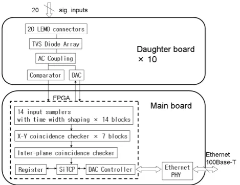
Fig. 1. Diagram of the observation system for multilayer muon high-speed radiography.
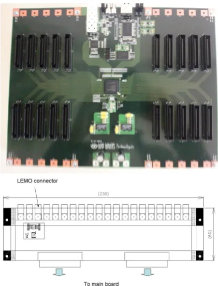
MURG12 readout module consists of a main board and 10 daughter boards, that are 305×235×60 mm3 each in size. Figure 2 shows a photograph of the main board and a schematic side view of the daughter board. The daughter board mounted on the main board plays a role as a signal fil-ter as well as a connector adapfil-ter to allow the use of various types of connectors. Each daughter board is in the shape of a slot card. As shown in Fig. 2, the main board has 10 pairs of slots for daughter boards (the daughter board uses two slots). Each daughter board has 20 LEMO connectors, a signal filter, and a comparator. A signal filter consists of transient voltage suppression (TVS) array to prevent damage to the main board from an accidental large current. The maximum acceptable charge is 10 nC (±100 V within 50 ns). The detector signals are received by the comparators and are digitized after they have been compared with threshold voltage. The threshold voltage is adjustable from−1000 mV to+50 mV. The mini-mum acceptable pulse width is 5 ns. The digitized signals are processed by the main board, and the main parts of this board are a field programmable gate array (FPGA) (Xilinx Spartan-6FPGA) and an Ethernet physical layer device (PHY). Fig. 3 shows a block diagram of the readout module. The event fil-ter, the histogram generator, and the network processor are implemented on the single FPGA.
The event filter selects candidate muon events for which the muon path can be constructed and generates information data on the paths. The signals from 14 x and y planes that consists of 196 scintillator strips (14 channels×14 layers) can be processed on the single FPGA. It is shown as “14 in-put samplers with time width shaping” in the block diagram in Fig. 3. The data consist of detection times and detection positions of all of the seven PSD planes for an off-line anal-ysis. The event filter selects a signal derived from single par-ticle passages through seven PSD layers. Such a selection is
30 1
2
Fig. 2. 3
4
Fig. 2. Photograph of the main board of MURG12 (upper) and the schematic side view of the daughter board (lower). U1 is for low voltage differential signaling. U2 is the low capacitance tran-sient voltage suppression (TVS) array. U4 is the low capacitance electrostatic-discharge- (ESD) protection diode array.
done by the PSD matrix coincidence system and only one hit events on a PSD layer are accepted. The event filter plays a role as a coincidence unit that selects events from the sam-pled signals and generates the information on the candidate muon path when the two signals of the counter are detected simultaneously on each PSD layer. This function is shown as “X–Y coincidence checker” in the block diagram. When two or more PSDs produce signals simultaneously and when a signal from one strip or adjacent two strips is produced from each PSD, the path information is generated through the function “inter-plane coincidence checker”. This deci-sion logic is called the multiplicity cut selection (Tanaka et al., 2001). The path information consists of the number of PSDs that produced signals, seven data sets containing the relative detection position differences from the first vertex point in the hodoscope for horizontal and vertical scintilla-tor strips and timings. These data are read by the network processor and accessed by a data acquisition (DAQ) PC to download them. The time windows for both of “X–Y coin-cidence checker” and “inter-plane coincoin-cidence checker” are adjustable from 10 ns to 160 ns through a silicon transmis-sion control protocol (SiTCP) utility software.
31 1
Fig. 3. 2
3
4
5
6
7
8
Fig. 3. Block diagram of MURG12.
MURG12 requires an external memory device (such as a DAQ PC) because the size of the internal memory is too small (2088 kbit: 18 kbit (9 bit×2 kword)×116) to store the data. The internal memory is used for register files of MURG12 and SiTCP, and only the real-time data are tempo-rary buffered in the FPGA. The time stamp of the data sets is therefore generated from a PC real-time clock (a clock that keeps track of the time even when the computer is turned off). These data are temporarily stored into a local hard disk drive in the DAQ-PC for various checks and are subsequently zipped and transferred to the remote terminal using a high-speed mobile phone network. Except for this part, no CPU and no other programmable sequencers are required. This design has advantages in terms of power consumption and operation failure rate. The measured power consumption of the readout module is 20 W. The anti-shower selection and histogram generation are done with an external PC at this stage. The procedure is explained in the next paragraph.
As stated before, only events giving signals in all seven PSD are kept. Moreover, the recorded positions in the PSD need to be consistent with a straight line. For this, a histogram is filled with the angle of the incident particle, calculated from each pair of PSD in the detector (a total of combina-torics of 7 by 2, i.e., 21 entries). If the standard deviation of the obtained distribution is larger than a threshold value of 200 mrad, the event is discarded. The angular distribution of the events accepted by this selection is saved in the data stream.
3 Test measurement with the multi-PSD system
In order to confirm the feasibility of this technique, the multi-PSD system comprised of four multi-PSDs and MURG08 modules were used by Kusagaya et al. (2012) to image the parasitic cone and the adjacent craterlets formed in the 1910 eruption
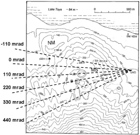
Fig. 4. Topographic sketch map of the Usu volcano. KP: Kom-pira craterlet group, MS: Meiji-Shinzan craterlet group, NM: Nishi-Maruyama mound, HM: Higashi-Nishi-Maruyama mound, SS: Showa-Shinzan lava dome, YH: Yanagi-Hara mound. Muon detection sys-tem is placed at UVO: Usu Volcano Observatory in this map.
at the base of the Usu volcano, which is shown in topographic sketch maps in Figs. 4 and 5. The detection system is located about 300 m east from the summit of the hill MS in the figure. Considering the speed limitations of MURG08 module, only 11 scintillator strips were used for each plane.
In this test measurement, the detection system consists of 88 scintillator strips to make an active area of 1.21 m2with an angular resolution of±110 mrad (±55 mrad at 75 % cov-erage). The candidates for muon events were requested to satisfy the following conditions:
a. The number of hits in each PSD must be 1.
b. The track obtained in each PSD combination must be on a straight line within the angular threshold of 200 mrad (anti-shower selection).
c. The track obtained for each muon candidate must have penetrated rock with a thickness of at least 100 m. Figure 6 shows the density distribution as obtained with the test measurement. The error includes the statistical er-rors at 1σ confidence level (CL) and the systematic errors that were estimated by two independent measurements us-ing different combinations of scintillator strips. Because the geometrical acceptance becomes smaller for larger negative azimuth angles, error bars tend to be larger. The accuracy in the density measurement is±2 % in 290 h for the maximum geometrical acceptance. The direction of the highest density coincides with that of the largest crater A. Although there are other two higher density regions forϕ= −330 mrad and
H. K. M. Tanaka and I. Yokoyama: Possible application of compact electronics 267
33 1
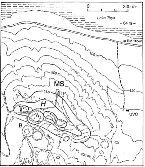
Fig. 5. 2
Fig. 5. Topographic sketch map of the MS area as of the year 2000, originally surveyed by the Geographical Survey Institute in the scale of 1/5000. A, B and C denote the craterlets muon radiographically surveyed in the present paper. NM is Nishi-Maruyama, unknown its origin.
34 1
Fig. 6. 2
3
4
5
6
7
8
Fig. 6. Density distribution of 1910 MS mound as a function of azimuth angle. The 1σ upper and lower limits for the measurement is shown in the blue region. The broken line shows the result of taking moving average of the density distribution. The solid line indicates the thickness of the target at an elevation of 110 mrad.
As shown in Fig. 6, the typical path length ranges from 500 to 1000 m for ϕ< 500 mrad, but it exceeds 1000 m for ϕ> 500 mrad. The lower density region can be seen for ϕ<−660 mrad. It is probably not because the density decreases, but because the signal-to-noise ratio increases. Based on this test measurement it was clarified that the BG rate with four PSDs are comparable to the muon penetration flux for 1000 m rock.
Tanaka et al. (2007b) reported that the observation time to resolve the density structure of the similar sized target (Showa-shinzan lava dome in Fig. 4) was four months. Even
though we consider the size of the detector they used was 1/3 of the present system (4000 cm2), the imaging speed is improved by a factor of three. The measured data transfer rate between MURG12 and the PC was 0.6 Gbit s−1for the test system (four PSD layers×22 scintillator strips). This means that the rate from the full system (seven PSD lay-ers×28 scintillator strips) will be 1.3 Gbit s−1. The rate of the events that hit three PSD layers and four PSD layers si-multaneously is∼26000 h−1and∼11000 h−1, respectively, after multiplicity cut selection but before non-linear cut se-lection. The difference in counting rate comes from the solid angle of the hodoscope.
In outdoor cosmic ray muon radiography measurements, it is necessary for us to collect a sufficient number of muon counts to visualize the inside structure of a gigantic body. For this purpose, our scintillator-based detection system re-quires only 10–20 channels per plane. This requirement is justified by the following discussions. Firstly, the realistic ac-tive area of the detector may range from 1 to 5 m2, depend-ing on the size of the housdepend-ing. The detector size exceeddepend-ing 5 m2is unrealistic for outdoor measurements. Since near hor-izontal cosmic ray muon flux is∼10−2sr−1m−2s−1 after passing through 1 km rock, depending on its average density, the muon counts ranging from 103to 104sr−1day−1will be detected with this size of the detector. In order to accom-plish the measurement within a realistic observation duration (< 1 month), it is therefore concluded that 10−3sr is the lower
limit of the solid angular resolution of the detection system in order to acquire the muon counts more than 100 (with less than 10 % statistic error at one sigma CL). This angular reso-lution can be realized by placing two PSD planes consisting of 10 cm wide scintillator strips at a distance of 3 m. On the other hand, one of the most important aspects in realizing outdoor muon radiography measurements is the power con-sumption. The minimal system instruments obviously helps to reduce the power consumption. In conclusion, for our pur-pose, 10–20 channels per plane is sufficient for imaging a km scale object such as a volcano in a realistic observation time. Our present development of MURG12 employs much faster FPGA (1050 MHz clock) in comparison to prior version of MURG (50 MHz clock). However, the power consumption per channel is slightly reduced from 0.11 W to 0.10 W in-cluding the consumption by the power supply.
One other important requirement for the electronics is higher availability (the ability of the users to access the sys-tem) to general users. Uchida et al. (2009, 2010) developed MURG08 for non-particle physicist users. In this system, in order to increase the availability, the tracking analysis al-gorithm is also incorporated into FPGA so that users can monitor the single counting rate of each channel as well as the 2-D histogram of the muon counts as a function of az-imuth and elevation angle only by accessing the web browser equipped on the electronics board via the internet. Thus far, this system has been used in various outdoor targets (Tanaka et al., 2009b, 2010, 2011), and the long-term (> 1 yr) sta-bility and reliasta-bility have been confirmed. There are two ways to apply MURG08 to the multilayered PSD system: (a) software-based parallel processing 48-channel MURG08 modules; and (b) redesigning MURG08 to realize a com-plete hardware processing. Firstly, software-based parallel processing MURG08 modules were tried with a power effec-tive laptop computer (∼10 W). In a track reconstruction soft-ware, a buffer is allocated in a memory for positioning and timing data that correspond to ∼2000 muon tracks. When operation failures occur, this buffer is rapidly consumed by unprocessed data and eventually the process stops. We found that this parallel processing system could successfully handle four planes, each with 11 X and 11 Y strips, although opera-tion failure would occur if the number of channels increased. The operation failure rate depends on the combination of the planes but it is roughly 140, 1200 and 1600 tracks h−1 for two, three and four planes each with 14 X and 14 Y strips. We therefore redesigned MURG08 to keep its availability, but we can still process seven planes, each with 14 X and 14 Y strips without any CPU load.
4 Review of eruption activities of the Usu volcano
In advance of the volcanological discussion of results of the test measurement, the volcanic activities of the Usu volcano will be briefly reviewed.
A simplified topographic map of the Usu volcano is shown in Fig. 4 that indicates several lava domes and upheavals (cryptodomes and mounds) in the summit crater and at the eastern and the northern bases. In the figure, HM (Higashi-Maruyama) may have a similar origin to MS (Meiji-Shinzan) that shall be studied in the present paper while the origins of KP (Kompirayama) and NM (Nishi-Maruyama) have not been analytically established. Their formations were histori-cally recorded at various accuracies, and their magmas were all dacitic. The two lava domes, Ko-Usu (small Usu) and Oo-Usu (big Oo-Usu) at the summit, were formed in 1822 and 1853, respectively. Their formations were orally recorded, but not scientifically. These summit lava domes may have directly derived from the magma reservoir, and may keep different subsurface structures from parasitic domes. Since 20th cen-tury, every event was observed by geophysical and geological methods of those days. It may be said that the activities of the Usu volcano are manifestations of characteristics of dacitic magmas (i.e., high viscosity). The recent four eruptions are briefly remarked in the following sections:
4.1 The 1910 eruption
More than 40 craterlets of small and large diameter were produced at the northern base of the Usu volcano roughly along the contour of 200 m a.s.l. They can be grouped into two, MS group and Kompira (KP) group (one is isolated as shown in Fig. 4). In the MS area, the ground upheaved about 70 m forming a hill (named MS hill) that is believed to be a “cryptodome”, which is defined as an upheaval caused by viscous magmas at very shallow depths. At KP area, any deformations were not particularly reported. At that period, seismometers were operated at Sapporo, about 100 km away, and a temporal seismic observation was carried out at the base of the volcano, and the routes of precise levels passed by the volcano. MS hill was named “Meiji-Shinzan” (the new mountain formed in Meiji era). Omori (1911), left volumi-nous synthetic papers discussing explosions, earthquakes and deformations observed in the 1910 eruption.
4.2 The 1944 eruption
H. K. M. Tanaka and I. Yokoyama: Possible application of compact electronics 269
abbreviated as SS in Fig. 4. Minakami et al. (1951) gave full details of this eruption.
4.3 The 1977 eruption
Magmatic eruptions took place within the summit crater pro-ducing 20 vents in total for 14 months and were followed by continuous tilts of the summit with incessant earthquakes for about 5 yr. Immediately after the commencement of this eruption, a volcano observatory was established at the north-ern base of the volcano by Hokkaido University and was equipped with telemetering systems of various kinds of sig-nals. Yokoyama et al. (1981) reported the results of geo-physical observations of this eruption. Later Yokoyama and Seino (2000) interpreted the three eruptions (1910, 1944 and 1977) from the standpoint of geophysical processes.
The 2000 eruption: firstly phreatomagmatic explosion out-bursts and later phreatic outout-bursts frequently occurred at the northwestern base forming more than 60 vents including small ones, and their activities were observed and discussed by members of various institutes. Their results were pub-lished in 27 papers on Bull. Volcanol. Soc. Japan (Vol. 47, 2002, in Japanese with English abstracts).
4.4 Muon radiography of the 1944 Usu domes
To the 1944 lava dome, Showa-Shinzan (SS in Fig. 4), muon radiography was already applied by Tanaka et al. (2007b) and the result was interpreted by Tanaka and Yokoyama (2008). The temporal sequence of the dome formation was visualized by the results of repeated precise levels (Minakami, 1947 and Yokoyama, 2002): the top of magma branch was below the aquifer that ranged from 200 m b.s.l. to 100 m a.s.l., in June 1994, and the ground continued to upheave. In August, the magma came in contact with the aquifer causing explosions, and in November, the magma tip exposed itself at the sum-mit of the mound. Thereafter the magma still continued to rise and simultaneously expanded laterally forming a bulbous structure. In September 1945, the SS lava dome finally com-pleted its upheaval of relative height at about 300 m, or about 110 m above the mound.
The muon radiography revealed the internal structure of the upper part of SS lava dome: the top of the dome tak-ing a bulbous shape measurtak-ing about 300 m in diameter and narrowing downwards. The diameter of the uppermost part of the conduits estimated at 100±15 m at an elevation of 260 m a.s.l. and 50±15 m at an elevation of 217 m a.s.l. Such a structure agrees with the results of deformation analyses (Tanaka and Yokoyama, 2008).
In the present study, muon radiography is applied to the area of the 1910 eruption, i.e., Meiji-Shinzan including the MS hill and the area of several craterlets. The detectors were set at the Usu Volcano Observatory and aimed at the MS area, specifically A, B and C craterlets as shown in Fig. 5. The
3
5
1
F
ig
. 7
.
2
3
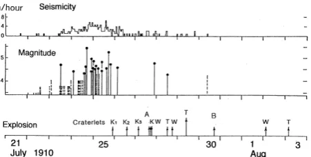
Fig. 7. Temporal sequences of the 1910 eruption of the Usu volcano (after Yokoyama and Seino, 2000). Seismicity: hourly numbers of earthquakes (M≥3.0) observed at Sapporo. Explosion: strength in arbitrary scale. Craterlets K: Kompira group.
distances from the detectors to the targets ranged from 470 to 800 m.
5 Discussion
5.1 New findings on the 1910 eruption of the Usu
vol-cano from the present test measurement
The temporal sequence of the 1910 eruption is not clear be-cause the volcano was located at a remote district at that time, and many explosive vents, small and large in diame-ter, opened at random in time and order, and their durations were relatively short. A temporal sequence of vent activity in the eruption provided by Omori (1911) is illustrated in Fig. 7 that contains some ambiguity according to the above reason. In the figure, the explosion diagram mainly indicates the periods of the first explosion of each craterlet, and each explosion did not continue for more than a few days. Some of the craterlets were reported to have repeated explosions. In Fig. 7, it is clear that the craterlets began their activities after the main seismic activities almost calmed. This means that a few magma branches had been completed by this period and thereafter many sub-branches fed various craterlets. Some-times strong magma branches such as A and B craterlets had formed upheavals on the ground surface.
Since we did not have three-dimensional tomographic in-formation in 1910 lava dome, we cannot assume the shape of the conduit. However, by assuming the density of dacitic lava in 1910 lava dome and the surrounding soil are both close to the average density measured in 1944 lava dome (Showa shinzan; 2.7 g cm−3) and surrounding soil (1.8 g cm−3) with
muon radiography (Tanaka et al., 2007b), it is concluded that the circular conduit cannot explain the data. As can be seen in Fig. 6, the measured average density is 2.4 g cm−3(by taking the average value between two independent measurements), and the muon’s path length is 700 m. Therefore, we can cal-culate that the magma is extended 470 m towards the direc-tion perpendicular to the detector plane. On the other hand,
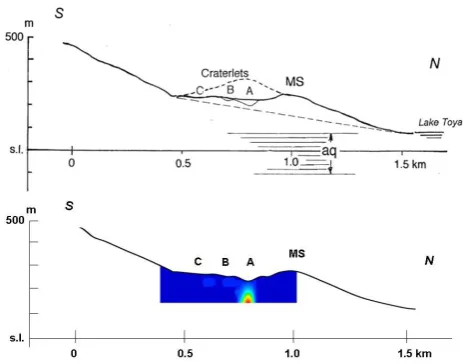
36 1
Fig. 8. 2
3
Fig. 8. A topographic profile in a south–north direction passing MS hill and the craterlets. “aq” indicates the aquifer observed at well GSH-1 (Fig. 5) (upper). Density projection as calculated from the result of muon radiography (lower).
the short axis of the magma measures about 100 m. There-fore, the shape of the dike rather than the conduit is reason-able to explain the “muographic” data.
a. The MS hill (so-called cryptodome): a simplified topo-graphic sketch map around the MS triangulation point is shown in Fig. 5, originally surveyed in the scale of 1/5000 by the Geographical Survey Institute in the year 2000. After one century, small or shallow crater-lets have faded or disappeared on the map. In Fig. 5, it is noticeable that MS hill itself is not located at the center of a parasitic cone measuring roughly 1 km in diameter on the northern slope of the Usu volcano, and lacks the SW slope of the cone. In that part, there were several craterlets that repeated explosions in 1910, and the upper part of the parasite was not built conically. Here the main craterlets are labeled A, B and C in Fig. 5. We can find many photos of the explosions at these craterlets in the report of Omori (1911).
The topographies around the MS area are projected on north–south profile as shown in Fig. 8 where the orig-inal northern slope is assumed to be linear because we do not know exact topography before the 1910 eruption. In the 1910 eruption, the northern slope of the volcano entering into Lake Toya and measuring roughly 1 km-long upheaved about 70 m at the maxi-mum forming the MS hill.
Beneath the MS hill, no dense material is detected with the test measurement as shown in Fig. 8 (bottom). As for the underground conditions in this area, we re-mark the distribution of aquifers that should react with extruding magmas. Well (GSH-1) was drilled at the western base of Nishi Maruyama (NM hill) in 1970
(Fig. 4). If the present aquifer is assumed to be the same as in 1910, its bottom may be roughly 100 m b.s.l. as shown in Fig. 8 (top). If the magma head beneath MS hill contact with the aquifer, an explosive activity should occur. No explosive activity around the top of MS means that the magma head had remained deeper than 100 m b.s.l. This interpretation agrees with that the muon radiography does not detect any dense mate-rial at a shallow depth. MS point had upheaved about 70 m and the deformed area including MS is roughly 1 km in basal diameter on the northern slope of Usu volcano (Figs. 4 and 5). In fact, the true center of the upheaval should be located at the area of A and B craterlets, and their explosions obstructed upheaval of the area. If MS were the peak of the upheaval caused by magmatic forces, we should observe dense material beneath it by the muon radiography. As a result, MS hill is not a cryptodome but a volcanogenetic mound. b. Craterlet A: this is the biggest craterlet of this group
still having a depth of about 43 m, as of the year 1910 and about 32 m in the year 2000. This magma body should have reacted with the aquifer causing violent phreatic explosions. This picture is consistent with a relatively narrow (50 m in diameter) high density anomaly that was found just beneath the craterlet in the direction of Craterlet A in Fig. 8 (bottom). If a simple dilatation model is adopted to explain the formation of a large MS cone, the rising magma branch beneath craterlet A should most probably be the pres-sure source.
c. Craterlet B: its maximum relative depth is about 12 m as of the year 2000. The muon image shows statisti-cally insignificant but some implication of dense ma-terial just below the craterlet as shown in Fig. 6. This craterlet may have exploded by reactions with the aquifer as well as craterlet A.
d. Craterlet C: it is a shallow craterlet measuring about 8 m in relative depth as of the year 2000. Below this craterlet, no dense material exists: probably a thin con-duit issued phreatic material and exploded the sur-rounding ground. This is also consistent with our re-sult that no clear density anomaly was found beneath Craterlet C.
As a result, in the area covering the craterlets, up-heavals due to magmatic pressure acting mainly be-neath craterlets A and B may have been partly ob-structed by explosive activities of all the craterlets. e. Gravity anomalies: the Bouguer gravity anomalies
H. K. M. Tanaka and I. Yokoyama: Possible application of compact electronics 271
37 1
Fig. 9. 2
Fig. 9. Bouguer gravity anomalies in mgal around MS hill. High anomaly is predominant.
because the points concerned are in a narrow area. High anomalies roughly predominate at the craterlet zone and qualitatively suggest the existence of dense magmatic material beneath the craterlets.
5.2 Multilayer high-speed muon radiography to reveal
three stages of the magma intrusions at the base of the Usu volcano
As future targets of muon radiography, we may group the magma intrusions on the Usu volcano into three classes ac-cording to their intrusive depths and the surface phenomena. a. Yanagi-Hara (YH) upheaval in 1944: an example of volcanogenetic deformation of similar dimension to the upheaval of MS hill, but not accompanied with eruptions, shall be remarked; it occurred at Yanagi-Hara village, south of SS dome, roughly four months earlier than the start of formation of the SS dome. It is labeled YH in Fig. 4 and its deformation curves are shown in Fig. 10 after Inoue (1948).
The benchmarks were on the railroad passing in the north–south direction roughly parallel to River Os-aru (Fig. 4) and the YH point measuring at a height of about 43 m a.s.l. before the 1944 eruption had up-heaved about 23 m in about three months (February to April, 1944) as shown in Fig. 9. The maximum up-heaval in this area was estimated at about 30 m outside
38 1
Fig. 10. 2
Fig. 10. Upheavals of YH (Yanagi-Hara) in 1944 (after Inoue, 1948).
the railroad. This upheaval was not accompanied with any explosive or fumarolic activities, and the deforma-tion activity apparently migrated about 1.5 km north-ward after March, and actually another magma branch intruded at the new spot where Showa-Shinzan (SS) lava dome was formed by explosions and upheavals in about 15 months. The magma branch acted at YH was different from that resulted in SS dome because the dacitic magmas are viscous and cannot easily move horizontally, and furthermore, the active periods of YH and SS events were partly overlapped each other. For the YH event, we can refer the aquifer observed at well GS-R1 (Fig. 4) drilled in 1966. Its bottom is about 160 m b.s.l. At YH, the magma top may have re-mained at a depth of deeper than (43+200=) 243 m. The magma branch could upheave the ground 30 m in three months but did not contact the aquifer. The YH upheaval is a volcanogenetic mound, and the magma may have remained at a depth of over 300 m.
b. MS hill in 1910 (Meiji-Shinzan): below craterlets A and B, the magma branched from the main conduit of the Usu volcano rose up upheaving the ground and further contacted the aquifer at a depth of about 100 m b.s.l. causing phreatic explosions. Many magma branches provoked similar explosions producing many craterlets as shown in Fig. 4, but each activity contin-ued for rather short time. This means that the magma branches were not so voluminous. Magmas themselves could not extrude above the ground surface.
c. SS lava dome in 1944 (Showa-Shinzan): the magma branch originating SS lava dome passed through the above two stages successively. The magma finally ex-truded above the mound forming SS lava dome. The latter two stages (b and c) were verified by muon radiography. In the near future, by applying multilayer high-speed muon radiography to YH upheaval, a com-plete picture of three stages of the magma intrusions on the Usu volcano will be obtained.
6 Conclusion
The present system requires an external DAQ computer to store event by event data. Therefore, the total power con-sumption of the readout module exceeds 80 W. However, if the following parameters are fixed, event by event data will no longer have to be saved, and only histogram data and val-ues of event counters will be generated in an internal memory of the FPGA by employing the same processing method as MURG08: (a) the number of PSD layers and (b) anti-shower selection criteria. In the future work on Usu Volcano, the number of PSD layers will be optimized as a function of the size of the target.
By comparing with the prior study by Tanaka et al. (2007b), we confirmed that the multilayer PSD system with MURG08 improved that the imaging speed by a factor of three even with the relatively high operation failure rate. By employing a hardware-based MURG12, this speed will be further improved.
By the muon radiographic survey of MS mound, it was clarified that a magma branch below craterlet A rose to a depth of about 100 m a.s.l. and reacted with the aquifer caus-ing explosions. At the base of the Usu volcano, we know the three stages of magma extrusions: first, the magma stopped below YH mound, second the magma reached the aquifer beneath MS craterlets, and third (34 yr later), the magma ex-truded over the ground at SS lava dome. The latter twos were verified by the muon radiography, and the authors expect that subsurface structure of the YH mound should also be clari-fied by muon radiographic imaging.
Some volcanos have a lot of parasitic cones like the Usu volcano. In order to comprehensively understand the forma-tion history of such volcanoes with muon studies, it is ob-vious that we need to image many of these cones. The au-thors are anticipating that more efficient muon imaging will be possible by speeding up the muon measurements with a system with higher reliability, availability, and stability.
Acknowledgements. This work is a part of a collaborative research with T. Kusagaya, A. Taketa, T. Uchida, M. Tanaka, H. Oshima and T. Maekawa. The authors acknowledge them for valuable collaboration. S. Okubo is also acknowledged for valuable discus-sions. Special funding arrangements by related people of ERI and MEXT are acknowledged. The manuscript greatly benefited from the useful comments provided by C. Carloganu.
Edited by: K. Hoshina
References
Alvarez, L. W., Anderson, J. A., Bedwei, F. E., Burkhard, J., Fakhry, A., Girgis, A., Goneid, A., Hassan, F., Iverson, D., Lynch, G., Miligy, Z., Mousaa, A. H., Sharkawi, M., and Yazolinio, L.: Search for hidden chambers in the pyramids, Science, 167, 832– 839, 1970.
George, E. P.: Cosmic rays measure overburden of tunnel, Com-monwealth Engineer, 455–457, 1955.
Inoue, W.: A research report on seismicity and deformation related to the 1944 activity of Usu volcano, Bull. Seismol. Observ. JMA, 14, 9–24, 1948 (in Japanese).
Kusagaya, T., Tanaka, H., Taketa, A., Ohshima, H., and Maekawa, T.: Development of low noise cosmic ray muon detector for imaging density structure of Usu Volcano, Hokkaido, Japan, AGU fall meeting abstract, 3–7, December 2012, San Francisco, USA, http://fallmeeting.agu.org/2012/eposters/ eposter/p21a-1832/ (last access: 20 November 2013), 2012. Lesparre, N., Gibert, D., Marteau, J., Komorowski, J., Nicolin, F.,
and, Coutant, O: Density muon radiography of La Soufrière of Guadeloupe volcano: comparison with geological, electrical resistivity and gravity data, Geophys. J. Int., 190, 1008–1019, doi:10.1111/j.1365-246X.2012.05546.x, 2012.
Minakami, T.: Recent activituies of volcano Usu (1), B. Earthq. Res. I., 25, 65–69, 1947.
Minakami, T., Ishikawa, T., and Yagi, K.: The 1944 eruption of vol-cano Usu in Hokkaidu, Japan, B. Volvol-canol., 11, 45–157, 1951. Omori, F.: The Usu-san eruption and earthquake and elevation
phe-nomena, Bull. Imp. Earthq. Inv. Com., 5, 1–137, 1911.
Tanaka, H., Nagamine K., Kawamura, N., Nakamura, S. N., Ishida, K., and Shimomura, K.: Development of the cosmic-ray muon detection system for probing internal-structure of a volcano, Hy-perfine Interact., 138, 521–526, 2001.
Tanaka, H. K. M., Nakano, T., Takahashi, S., Yoshida, J., Takeo, M., Oikawa, J., Ohminato, T., Aoki, Y., Koyama, E., Tsuji, H., and Niwa, K.: High resolution imaging in the inhomogeneous crust with cosmic ray muon radiography: The density structure below the volcanic crater floor of Mt. Asama, Japan, Earth Planet. Sc. Lett., 263, 104–113, 2007a.
Tanaka, H. K. M., Nakano, T., Takahashi, S., Yoshida, J., Ohshima, H., Maekawa, T., Watanabe, H., and Niwa, K.: Imaging the con-duit size of the dome with cosmic ray muons: The structure be-neath Showa Shinzan Lava Dome, Japan, Geophys. Res. Lett., 34, L22311, doi:10.1029/2007GL031389, 2007b.
Tanaka, H. K. M. and Yokoyama, I.: Muon radiography and defor-mation analysis of the lava dome formed by the 1944 eruption of Usu, Hokkaido – Contact between high-energy physics and volcano physics, Proc. Jpn. Acad. Ser. B, 84, 107–116, 2008. Tanaka, H. K. M., Nakano, T., Takahashi, S., Yoshida, J., Takeo,
M., Oikawa, J., Ohminato, T., Aoki, Y., Koyama, E., Tsuji, H., Ohshima, H., Maekawa, T., Watanabe, H., and Niwa, K.: Radio-graphic imaging below a volcanic crater floor with cosmic-ray muons, Am. J. Sci., 308, 843–850, 2008.
H. K. M. Tanaka and I. Yokoyama: Possible application of compact electronics 273
Tanaka, H. K. M., Uchida, T., Tanaka, M., Shinohara, H., and Taira, H.: Cosmic-ray muon imaging of magma in a conduit: De-gassing process of Satsuma-Iwojima Volcano, Japan, Geophys. Res. Lett., 36, L01304, doi:10.1029/2008GL036451 2009b. Tanaka, H. K. M., Taira, H., Uchida, T., Tanaka, M., Takeo, M.,
Ohminato, T., Aoki, Y., Nishitama, R., Shoji, D., and Tsuiji, H.: Three-dimensional computational axial tomography scan of a volcano with cosmic ray muon radiography, J. Geophys. Res., 115, B12332, doi:10.1029/2010JB007677, 2010.
Tanaka, H. K. M., Miyajima, H., Kusagaya, T., Taketa, A., Uchida, T., and Tanaka, M.: Cosmic muon imaging of hidden seismic fault zones: Rainwater permeation into the mechanical fractured zones in Itoigawa-Shizuoka Tectonic Line, Japan, Earth Planet. Sci. Lett., 306, 3–4, 156–162, doi:10.1016/j.epsl.2011.03.036 , 2011.
Uchida, T., Tanaka, H. K. M., and Tanaka, M.: Space Saving and Power Efficient Readout System for Cosmic-Ray Muon Radiog-raphy, IEEE Transactions on nuclear science, 56, 448–452, 2009.
Uchida, T., Tanaka, H. K. M., and Tanaka, M.: Development of a muon radiographic imaging electronic board system for a sta-ble solar power operation, Earth Planets Space, 62, 167–172, doi:10.5047/eps.2009.03.002, 2010.
Yokoyama, I.: The formation of cryptodomes: Usu volcano, Hokkaido, Japan, Bull. Volcanol. Soc. Jpn., 47, 151–160, 2002 (in Japanese with English abstract).
Yokoyama, I., Yamashita, H., Watanabe, H., and Okada, Hm.: Geo-physical characteristics of dacite volcanism – The 1977–1978 eruption of Usu volcano, J. Volcanol. Geotherm. Res., 9, 335– 358, 1981.
Yokoyama, I. and Seino, M.: Geophysical comparison of the three eruptions in the 20th century of Usu volcano, Japan, Earth Plan-ets Space, 52, 73–89, 2000.