DOI: 10.22075/JRCE.2019.17441.1329
Journal homepage: http://civiljournal.semnan.ac.ir/
Study and Comparison of Seismic Behaviour of
Isolator-Damper Hybrid Control System with Conventional
Structural Systems
A.A. Mazloum1 and M. Amin Afshar2*
1. Graduated Master in Structural Engineering, Imam Khomeini International University, Qazvin, Iran 2. Assistant Professor, Structural Engineering, Imam Khomeini International University, Qazvin, Iran
Corresponding author:[email protected]
ARTICLE INFO ABSTRACT
Article history:
Received: 12 March 2019 Accepted: 26 September 2019
In this paper, in addition to introduce a hybrid structural system
contained local isolators and dampers, its behavior and
functional capabilities were studied on a conventional structure. For this purpose, an RC frame building with six-story was designed based on valid codes and then, in four cases based on the number of spans, it was split into two separate adjacent frames. Base isolation was done underneath the columns of one frame, while the bottom connections of the other frame’s columns were remained fixed and viscous dampers provided the connection of two adjacent frames on the same floors. Nonlinear time history analysis (NTHA) under three near-fault and three far-fault earthquakes and frequency-domain analysis are performed. Displacement, drift, acceleration and shear forces of the stories in the four proposed hybrid cases with two limited cases, full base-isolated and full base-fixed frames, as well as nonlinear hysteresis behavior of a damper and an isolator are assessed. The results showed that using the novel hybrid control method in most cases can mitigate deteriorating effects of all types of seismic motions observed in the conventional structural systems. However, among them, two cases (2 isolated columns -5 fixed columns and 3 isolated columns -4 fixed columns) had the best significant influence on
seismic performance and structural response reduction.
Furthermore, frequency response functions of displacement and acceleration with respect to ground acceleration demonstrated that the two proposed cases further suppress the responses of the limited cases, over a wide range of frequencies including all natural frequencies. Due to decrease about 50-70% in the number of base isolators (compared to full isolation) lead to considerable construction cost savings. In spite of the limitation of ASCE7-10 code on separately using base isolators and
dampers on structure, applying the proposed combination
technique of these two dissipating devices can overcome the limitation.
Keywords: Hybrid Control, Viscous Damper, LRB Isolator, Local Isolation,
1. Introduction
In most large cities, buildings are constructed at more height and nearby places, due to population growth and lack of space. Most structures during the operation period will in some way be influenced by lateral loads. Samples of lateral loads are generated by earthquake, wind or explosion loads. These loads have mainly caused lateral displacement of buildings, especially in high seismic regions. Buildings’ displacement due to sudden movement as well as their adjacency to each other caused destruction, or serious damage to buildings. On the other hand, during the earthquake, two main factors, the lateral displacement and absolute acceleration of the stories caused by strong ground motions, have severe effects on the damage to structural and nonstructural members. Due to the prevention of these events, some preparations have been made in the science of structural control. Two manners, using isolators at the base of buildings (base isolation system) and connecting adjacent structures by dampers are one of the most commonly used methods of the passive control domain. The idea of isolators was introduced in the early 20th century and was widely studied and implemented by engineers over the past years on structures. These researches include the construction of Lead Rubber Bearing (LRB) in 1969 by the Swiss engineers and isolator design legislation in the National Building Regulations since 1991 and seismic strengthening of structures of San Francisco in the late 20th century [1]. So far, many studies have been done on the recognition and usage development of different types of isolators in a variety of regular and irregular structures [2-5]. In order to reduce and prevent the pounding of adjacent structures,
external structure by dampers. They also proposed to design this second structure as an external cladding, which would be able to improve the energy performance of the existent building and to remodel the aesthetic of the facade. Matsagar and Jangid [12,13] studied on the effectiveness of a hybrid control method including the base isolation and mid-linking viscoelastic dampers for two adjacent buildings and emphasized that the large displacement of the isolators under the buildings is controlled and reduced by connecting them with viscoelastic dampers. Bharti et al. [14] proposed another way of synchronous controlling the adjacent structures, in which semi-active MR dampers connecting the same level stories of two adjacent structures, where applied by an effective control method to reduce their seismic response. Shrimali et al. [15] used an elastomeric base isolation system for a building which is connected to adjacent building by MR damper, and proposed semi-active control method for controlling adjacent buildings. The results of numerical study showed that Hybrid controls are more effective in controlling the response as compared to Semi-active control. In other researches, Kasagi et al. [16] and Hayashi et al. [17] proposed a new base isolation hybrid control system underneath the building and connection it with the free rigid wall (for example a braced tower or a shear wall) by dampers. This system has two advantages, (1) to resist against impulsive earthquakes through the base-isolation system and (2) to withstand against long-duration earthquakes through the building-connection system. Amini et al. [18] proposed semi-active and active control devices within a base isolation system besides using online damage detection algorithm, to overcome some weakness of conventional isolation system
isolation was done underneath the columns of one frame, while the bottom connections of other frame’s columns were remained fixed and viscous dampers provided the connection of two adjacent frames at the same stories level. By defining nonlinear structural elements, nonlinear isolators and linear viscous dampers in all cases, nonlinear time–history analysis (NTHA) is performed by OpenSees software. It was observed that two cases of the proposed hybrid frames (2 isolated columns -5 fixed columns and 3 isolated columns -4 fixed columns) had the optimal performance in controlling and reducing the responses of structure against earthquakes (shown in Table 5). Another objective of this paper was to verify the accuracy of the ASCE7-10 regulation parts [20] about the limitation for the use of isolators and dampers in Chapters 17 and 18 (when the coefficient S1 is larger than0.6),
respectively and whether synchronously use of these two energy dissipation systems can perform properly, and causes ignoring these constraints.
2. Modeling
2.1. Modeling the Structure
In this paper, a six-story story RC intermediate moment resisting frame building, located in Los Angeles, USA, with six spans and structural plan shown in Fig. (1) was studied. For modeling this building, ETABS software was used and its design was based on the ACI318-14 [19] and ASCE7-10 [20] codes. To analyze the nonlinear time history, OpenSees software has been used. Due to the regularity of the structure, the frames located along the longitudinal and transverse directions will appear independent and non-coupling lateral behaviors; also in his study, the horizontal excitation is exerted only along the longitudinal direction of the
building. So, in order to simplify the analysis, only a two-dimensional frame located on the A axis is selected and modeled in OpenSees software. It is evident that because of the above reasons, the results of the seismic performance of frame A axis are similar and generalizable to two longitudinal frames located on axes B and C. The geometric and mechanical characteristics of this building are commonly described as follows; the distance between the spans, the height of the floors and the height of the ground floor are 5, 3.2 and 2.8 meters, respectively. Characteristic strength of concrete, 𝑓𝑐 is equal to 30 MPa and yield strength of steel bar, 𝑓𝑦 is 390 MPa. In accordance with Table 12.2.1, the coefficient of structural behavior, 𝑅, the coefficient of extra strength, Ω, and the elastic displacement increase coefficient, 𝐶𝑑, are
respectively equal to 5, 3 and 4.5 for intermediate moment resisting frame building. Based on the soil type of the building site location (group D), as well as the level of importance of the building (ш), the seismic parameters of the USGS site are calculated as 𝑆𝑆 = 2 ∙ 442𝑔 and 𝑆1 = 0 ∙
limitation on this new structural system under nonlinear time history analysis (NTHA) is also evaluated.
Fig. 1. Building plan.
2.2. Modeling of Isolators and Dampers In the design of isolators, according to ASCE7-10 [20] and FEMA451 [21], and their bilinear force-displacement behavior, a design displacement, 𝐷𝑑 , is considered for the displacement of isolators. 𝐷𝑑should be less than the maximum displacement, 𝐷𝑀,
specified in the code. Eqs. (1) and (2) are derived from ASCE7-10 [17]. TD and TM are equal and in terms of experimental relations, they are approximately three times larger than the first period of a conventional building. The seismic coefficients of the site,
𝑆𝐷1(= 2
3𝑠𝑀1 ) and 𝑆1 , are so-called design
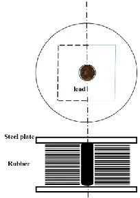
spectral acceleration parameter and mapped acceleration parameter, respectively. They can be obtained from either the USGS site [22] or Chapter 22 of the ASCE7-10 [20]. Fig. (2) is a schematic view of the LRB isolator applied in this study.
Dd =g∗SD1∗TD
4π2∗B
D (1) DM = g∗SM1∗TM
4π2∗B
M (2)
Fig. 2. Schematic view of LRB isolator The coefficient Ddin 6-story building, which was based on static analysis, is calculated 0.31 meter. The geometric characteristics of isolators which are defined by KikuchiAikenLRB model as uniaxial material in OpenSees software, have been displayed in Table 1.
Eq. (3) is used to design the dampers between two adjacent structures [23]. In Table 2, all parameters of this equation were explained. Moreover, the admissible range of the exponential coefficient for velocity of damper’s deformation, α, is between 0 and 1. For using linear viscous damper, the coefficient is selected equal to 1. The priority of choosing a building number (defined as second subscript) is based on the lower height, or for structures with equal height in this study, the lower weight. Total damping ratio, 𝜉𝑑 is selected equal to 15% and for the horizontal arrangement of dampers, 𝜃𝑗 is zero.
ξd=
(max{T1.1. T1.2}) ∑ 𝐶j 𝑑(α)j𝑐𝑜𝑠2(𝜃𝑗)(ϕj.1−ϕj.2)2
4π ∑ mi iϕi2 (3)
Table 1. Geometric Property of Isolators*.
Metal layer thickness Rubber layers
number Rubber layer
thickness Isolator height
Isolator diameter Lead core
diameter case
0.16 48
1.3 61
80 13
A.Iso
0.3 62
1 61
60 13
LI3RF4, LF3RI4
0.18 62
1 61
60 13
LI2RF5, LF2RI5
In the next step, ETABS 2016 and OpenSees were used to verify accuracy of modeling and some of the responses and properties of two structures modeled in different softwares, such as drift, displacement and percentage error of the first period of them, were compared in Table 3.
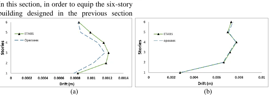
As shown in Fig. (3) and Table 3, for a six-story building in full-isolated case, the error rate of drift between the two OpenSees and ETABS models in all stories was about 6.91% and in the case of full-fixed at the same level of stories was around 1.31%. The above items indicate that the modeling was done correctly in OpenSees software.
2.3. Preparing Recorded Ground Motion Used in the Analysis
In this paper, six earthquake’s accelerations, including three far-fault and three near-fault earthquakes with soil type D, have been selected from FEMA P695 [24]. Their characteristics were listed in Table 4. These earthquakes were scaled based on the ASCE7-10 Code [20, 25]. In Fig. (4), the earthquake scaling process based on their spectrum is depicted in both far and near field.
2.4. Distributing Isolators and Dampers
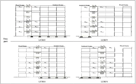
In this section, in order to equip the six-story building designed in the previous section
with the isolator-damper hybrid control system, based on the number of spans, this building was divided into two adjacent frames, which will be called the two-part building from now. Base isolation was done underneath the columns of one frame, while the bottom connections of other frame’s columns were remained fixed and viscous dampers provided the connection of two adjacent frames at same story’s levels.
Table 2. Design parameters of the dampers.
Explanation Parameter
Total damping ratio
ξ𝑑
First natural periods T1.2. T1.1
jth story displacement in the
first mode shape ϕj.1− ϕj.2
ith story mass of the first
building mi
Damping coefficient of the damper in jth story
𝐶𝑑𝑗
Angle of damper 𝜃𝑗
Exponential coefficient 𝛼
Table 3. Error Rate in ETABS and OpenSees
Models.
(a) (b)
Fig. 3. Drifts of ETABS and OpenSees models (a) the base-isolated case, (b the base-fixed case.
Case Building Period in ETABS
Period in OpenSees
Error rates (%)
F.F 6 0.715 0.709 0.84
Table 4. Characteristics of recorded ground motion earthquakes near and far fields.
(a) (b
Fig. 4. The scaled graph of the earthquakes spectrum of (a) the far field, and (b) the near field.
Since the main building frame has 6 spans and seven columns, the isolator-damper hybrid control system has been defined in four different configuration cases. In addition, the other two cases, which are actually more widely used in the
implementation and construction, have been defined and referred as limited cases, in order to comparison and evaluation with the 6 proposed ones. (See Table 5)
Table 5. Characteristics of the six configuration cases.
Configuration cases
limited
Full Base-isolated (A.ISO) Full Base-fixed(F.F)
RSN Rup (km) PGA
Vs30 (m/sec) Year
Station Magnitude
Earthquake Field
953 17.15 0. 52
355.81 1994
Beverly Hills 6.69
Northridge
Far Kobe 6.9 Kobe 1995 609.0 0.51 17.08 1111
1633 12.55
0.51 723.95
1990 Abbar
7.7 Manjil
1086 5.3
0.73 440.54
1994 Sylmar - Olive 6.9
Nothridge
Near Cape Mendocino 7.01 Petrolia 1992 422.17 0.63 8.18 828 143 2.05
0.86 766.77
1978 Tabas
Two-part LF2RI5 LI2RF5
LI3RF4 LF3RI4
The first limited case, referenced by F.F (Full Base-fixed), is same as the original or primary structure, which all of its columns were fixed to the ground. The second limited case, referenced by A.ISO symbol (All Isolators), is a case that all of its columns were isolated and no dampers are used. LI3RF4 is a case in which the isolators are installed underneath each three columns on the left part and four columns on the right part are fixed to the ground. In LI2RF5 case, the isolators are installed underneath each two columns on the left part and five columns on the right part are fixed to the ground. Also, the two cases LF3RI4 and LF2RI5, have the fixed and isolated columns arranged in the opposite manner of the two LI3RF4 and LI2RF5 cases, respectively. In table 5 all configuration cases are displayed separately.
3. Analysis Results
As mentioned previously, four configuration cases of the isolator-damper hybrid control
system as well as two limited cases are investigated to study their seismic responses under ground motion effects. In this section, results of the nonlinear time history analysis of three near-fault and three far-fault earthquakes and the frequency-domain analysis are conducted and presented separately for isolated and fixed parts of all cases.
3.1. Nonlinear time history results
The maximum and root-mean-square (RMS) values of each floor's time history response are computed for three earthquakes (far- or near-field type). According to ASCE7-10 [20], the allowable drift is defined as one-fifth the height of the story (i.e. 0.02h, where
h is the story height).
to limited cases (A.ISO and F.F). However, for all hybrid cases, a reasonable margin to the allowable drift of ASCE7-10 has been complied. In both far and near-fault, the isolated part of LI2RF5 showed the lowest response relative to other cases and also it is about 80% and 70% lower than A.ISO and ASCE7-10 code limitation, respectively. The isolated part of LI3RF4 case has drift 20% upper than A.ISO limited case, but considerably lower response than the allowable drift (about 40%). In other hand, in
fixed parts as shown in Figs. 5(b) and 5(d), LI3RF4 has the lowest response relative to other cases and also it is about 98% lower than A.ISO and ASCE7-10 code limitation. Operations of both parts of the hybrid cases show approximately a direct correlation between increasing numbers of fixed columns (or decreasing numbers of isolated columns) with reducing drifts of base-fixed frames, and increasing drifts of base-isolated frames.
(b)
(c) (d)
Fig. 5. Maximum of mean roof drifts under the far-fault and near-fault earthquakes respectively for (a, c) base-isolated frames and (b, d) base-fixed frames.
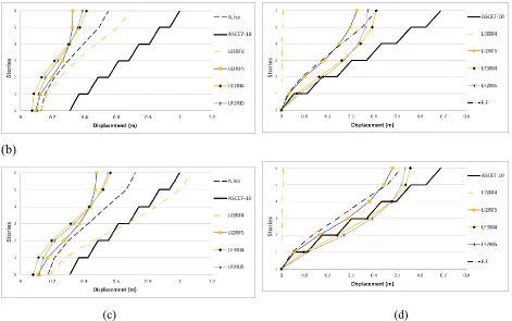
Fig. 6 shows maximum displacement values in different stories. Allowable displacements, based on the ASCE7-10 code, are computed by cumulative relation of allowable story drifts, i.e. ∑𝑗𝑖=10 ∙ 02ℎ𝑖 (where ℎ𝑖 is the height of the ith floor and j is the desired floor level) and in the graphs, they're shown with broken lines in bold black color.
overshoot exceeds the statutory limit. Also, LI2RF5, LF2RI5 and LF3RI4 have respectively the lowest displacements at the upper two floors (about 35% to 25% lower than A.ISO and approximately 60% to 50% lower than code limitation), but in the lower floors, they are in reverse order. It is important to note that, in the base-isolated frame the displacement responses in the near-field earthquakes are greater than those in the far-field ones, however, in both fields graphs
approximately follow the same trend. It can be observed in base-fixed frame as well. In Figs. 6(b) and 6(d), LI3RF4 shows the least responses (about 80% and 98%, relative to A.ISO and permitted limit, respectively) and LI2RF5 is the next priority. Both LF2RI5 and LF3RI4 cases show close displacements but more than F.F case and have inappropriate responses especially in the near field for the lower floors. By the way, LI2RF5 has the most suitable displacement response in Fig. 6.
(b)
(c) (d)
Fig. 6. Maximum of stories displacement under the far-fault and near-fault earthquakes respectively for (a, c) base-isolated frame & (b, d) base-fixed frame.
Comparison of the displacement graphs in Fig. 6, indicates exchanging distribution of displacements between two isolated and fixed parts of hybrid cases by increasing numbers of isolated columns, so that
increases displacements on one part and decreases them on the other part.
mention the limitation of ASCE7-10 code about the separately use of isolators in regions with the condition 𝑆1 > 0 ∙ 6, and state that the use of isolators in the A.ISO limited case has shown unacceptable shear results because the amount of stories' shear and their distribution were approximately the same as the F.F limited case. For instance, in Fig. 7(a) and 7(b), the shear force on the roof for the two cases of A.ISO and F.F are respectively about 237 kN and 298 kN. However, the results of the hybrid control cases are quite appropriate and with lower large margins from both A.ISO and F.F cases. For example, at the building base, LI2RF5 and LI3RF4 respectively, have about 80% and 50% reduction relative to A.ISO and
over 95% and 65% reduction relative to F.F. In Figs. 7(b) and 7(d), it is obviously clear that by increasing the number of base-fixed columns in order of LF2RI5, LF3RI4 and LI2RF5, the amount of shear forces is significantly increased in the fixed parts; while the reverse trend in the isolated parts is notable for these cases (See Figs. 7(a) and 7(c)). Thus, it can be interpreted that changing and increasing the number of base-fixed columns causes the Energy Exchange or Energy rearrangement from the base-fixed frame to the base-isolated frame. Of course, LI3RF4, as an exception, does not seem to have followed this manner.
(b)
(c) (d)
Fig. 7. Maximum root mean square of stories shear under the far-fault and near-fault earthquakes respectively for (a, c) base-isolated frame & (b, d) base-fixed frame.
Also, it can be declared that in spite of the larger shear forces under near-fault earthquakes versus their similar values under far-fault ones (about 5-10% larger in
Graphs in Fig. 8, which has been drawn semi- logarithmic, are the maximum root mean square responses for acceleration of floors under far- and near-fault earthquakes. From Figs. 8(a) and 8(c), it can be stated that all cases of the base-isolated frame experience almost uniform (or better said than the same order) accelerations in all stories. In other words, acceleration changes in the stories are negligible, which is due to the desirable performance of the base isolation system in the base-isolated frame. By considering the acceleration response of the full base-isolated frame (A.ISO) as the basis, it can be seen that LF2RI5 and LF3RI4 cases have responses beyond the A.ISO limited case, while the rest of the cases show a suitable performance in acceleration. Similar behavior is also visible for the
base-fixed frames. It can be seen from Figs. 8(b) and 8(d) that two hybrid cases, LI2RF5 and LI3RF4, in the base-fixed frame experience slight accelerations (less than F.F), especially in the lower stories; while the accelerations of the other cases, i.e. LF2RI5 and LF3RI4, are too far from those of F.F case. It means that the lateral resisting elements of the main structure, in two latter configurations of hybrid control, exhibit plastic behavior and so experience instability. Also, a review of Figs. (6), (7) and (8) together shows that both the base-isolated and base-fixed parts of the hybrid cases merely display their dominant (primary) mode shapes in displacements, shear forces and accelerations. They further correspond to the primary mode shapes of A.ISO and F.F cases, respectively.
(b)
(c) (d)
(b)
(c) (d)
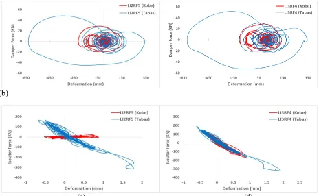
Fig. 9. Hysteresis loops of (a,b) the top floor damper and (c,d) the base isolator, under Kobe and Tabas earthquakes and for LI2RF5 and LI3RF4 cases, repectively.
(a) (b)
Fig. 10. Frequency response functions of (a) the roof displacement 𝑋𝑟, and (b) the roof acceleration 𝑋̈𝑟,
with respect to ground acceleration 𝑋̈𝑔.
For a damper connecting the top floors as well as an isolator used on two cases, LI2RF5 and LI3RF4, when subjected to Kobe and Tabas, respectively as the far- and near-fault earthquakes, nonlinear hysteresis
Also, their displacements and forces have the same trend with close intensity in both cases, LI2RF5 and LI3RF4.
3.2. Frequency-Domain Results
In Figs. 10(a) and 10(b), the frequency response functions 𝐻𝑋𝑟𝑋̈𝑔 and 𝐻𝑋̈𝑟𝑋̈𝑔 of the roof displacement 𝑋𝑟 and the roof acceleration 𝑋̈𝑟 with respect to ground acceleration 𝑋̈𝑔 and versus 𝜔 𝜔⁄ 1, i.e. the ratio between the excitation frequency and the first natural frequency of the main structure (F.F case) are plotted. The frequency response curves are presented for the main structure (F.F), the full isolated case (A.ISO) and partially base-fixed (P.F) and partially base-isolated (P.I) parts of two proposed hybrid cases, LI3RF4 and LI2RF5, which have shown the best performance compared to the other two cases.
As can be seen from Fig. 10(a), the main structure (F.F) experiences maximum peaks of frequency response amplitudes for its natural frequencies, especially for first one. But the plots of other cases exhibit more reduction of displacement peaks in identical frequencies. The minimum peaks of frequency responses are belong to A.ISO and partially isolated frames (PI), except for isolating frequency (about one tenth of fundamental frequency), where they reached about 1.5 and 0.5 time the maximum peak of F.F case, respectively. Furthermore, a significant reduction for base-fixed (PF) frames’ displacement responses is visible, especially in the primary frequency range (about one fifth of F.F displacement).
Form Fig 10(b), the trend similar to the displacement frequency function is also observed for the acceleration frequency function. The only difference, of course, is
the absence of a remarkable peak in the isolation frequency range, for A.ISO and the base-isolated frames.
The following points can also be noted; the proposed hybrid cases in both their base-isolated and base-fixed parts, as well as A.ISO and F.F cases, under frequency analysis have the same unchanged natural frequencies and corresponding mode shapes. In other words, the natural frequencies and mode behaviors of isolated parts are identical to those of A.ISO case and likewise, the modal quantities of fixed parts are identical to those of F.F case (i.e. the main structure). Therefore, it can be inferred that the lateral behaviors of both parts of the hybrid cases are independent of the main structure’s frequencies.
latter case and so has an economic advantage.
4. Conclusion
In this paper, a new energy-dissipating system was introduced to reduce the harmful effects of lateral loads applied to the buildings. As mentioned in the previous sections, it applies two techniques; first, detaching the main structure into two separate frames and then equipping them with an isolator-damper hybrid control system. Configuration of this hybrid system involves isolating a frame from the base and connecting it to its adjacent frame with dampers on the same height floors.The time-domain and frequency-time-domain results for four proposed hybrid cases were compared with the results of limited cases (A.ISO and F.F) and also with the permitted limit of the regulation. The NTHA results, under three far-fault and three near-fault earthquakes, included maximum drifts, maximum displacements and maximum root mean square of the shear forces and accelerations on each floor, as well as hysteretic loop curves for the connecting damper in top floors and the isolator.
The most important finding of this study can be summarized as follows:
1. According to A.ISO results, validity of the ASCE7-10 restriction on the use of complete isolation for specific earthquake conditions (𝑆1> 0.6) was confirmed; however, applying
the proposed hybrid control system removes this code limitation and overcomes the weakness of the fully isolation system. 2. Hybrid cases with less isolated columns, have less seismic responses of displacement, acceleration and shear force in both isolated and fixed parts. Considering correlation
between the absorption energy in a structure with displacement squares and shear forces, it was found that increasing the number of fixed columns (or decreasing the number of isolated columns) caused decreasing the input energy as well as the Energy Exchange or Energy rearrangement from the base-fixed frame to the base-isolated frame.
3. Among four hybrid control cases, both the LI2RF5 and LI3RF4 were considerably better in reducing the responses. It is obvious that LI2RF5, due to fewer numbers of its isolated columns against LI3RF4, has an economic advantage.
4. The seismic performances of both parts of the hybrid cases are independent of the main structure’s frequencies, or in another phrase, structural geometry parameters, such as number and length of spans. It means probably that, the same lateral behavior and results, obtained for this particular structure (with six spans) can be generalized and observed in the other structures with different numbers or length of spans.
5. Both limited cases, F.F and A.ISO, are upper and lower bounds for frequency response functions of the isolated and fixed parts of the hybrid cases, especially near their natural frequencies.
6. Another worthy point is that applying the proposed hybrid control strategy on the conventional structures, leads to greater reductions of responses over a much broader range; consist of all natural frequencies as well as small isolating frequency. Therefore, its good seismic performance is less frequency dependent, especially in the presence of broad-band earthquakes.
directions, the two- dimensional separation is not efficient. It is necessary to consider other detaching and separation techniques for 3D structures and also, their 3D modeling in software is required. This topic will form the basis for further research.
REFERENCES
[1] Naeim, F., & Kelly, J. M. (1999). Design of seismic isolated structures: from theory to practice. John Wiley & Sons.
[2] Kilar, V., & Koren, D. (2009). Seismic behaviour of asymmetric base isolated structures with various distributions of isolators. Engineering structures, 31(4), 910-921.
[3] Afshar, M. A., & Aghaeipour, S. (2016). On inertia nonlinearity in irregular-plan isolated structures under seismic excitations. Journal of Sound and Vibration, 363, 495-516.
[4] Harvey Jr, P. S., & Kelly, K. C. (2016). A review of rolling-type seismic isolation: Historical development and future directions. Engineering Structures, 125, 521-531.
[5] Radkia, S., Rahnavard, R., & Gandomkar, F.A. (2018) Evaluation of the effect of different seismic isolators on the behavior of asymmetric steel sliding structures. Journal of Structural and Construction Engineering (Article In Press) DOI: 10.22065/jsce.2018.114089.1428.
[6] Ni, Y. Q., Ko, J. M., & Ying, Z. G. (2001). Random seismic response analysis of adjacent buildings coupled with non-linear hysteretic dampers. Journal of Sound and Vibration, 246(3), 403-417.
[7] Patel, C. C., & Jangid, R. S. (2010). Seismic response of dynamically similar adjacent structures connected with viscous dampers. The IES Journal Part A: Civil & Structural Engineering, 3(1), 1-13.
[8] Takewaki, I. (2007). Earthquake input energy to two buildings connected by viscous
dampers. Journal of Structural Engineering, 133(5), 620-628.
[9] Hwang, J. S., Wang, S. J., Huang, Y. N., & Chen, J. F. (2007). A seismic retrofit method by connecting viscous dampers for microelectronics factories. Earthquake engineering & structural dynamics, 36(11), 1461-1480.
[10] Li, H., Wang, S. Y., Song, G., & Liu, G. (2004). Reduction of seismic forces on existing buildings with newly constructed additional stories including friction layer and dampers. Journal of sound and vibration, 269(3-5), 653-667.
[11] Passoni, C., Belleri, A., Marini, A., & Riva, P. (2014). Existing structures connected with dampers: state of the art and future developments. In 2ECEES: 2nd European Conference on Earthquake Engineering and Seismology, Istanbul, Turkey, 24-29 August 2014. EAEE (European Association of Earthquake Engineering). [12] Matsagar, V. A., & Jangid, R. S. (2003).
Seismic response of base-isolated structures during impact with adjacent structures. Engineering Structures, 25(10), 1311-1323.
[13] Matsagar, V. A., & Jangid, R. S. (2005). Viscoelastic damper connected to adjacent structures involving seismic isolation. Journal of civil engineering and management, 11(4), 309-322.
[14] Bharti, S. D., Dumne, S. M., & Shrimali, M. K. (2010). Seismic response analysis of adjacent buildings connected with MR dampers. Engineering Structures, 32(8), 2122-2133.
[15] Shrimali, M. K., Bharti, S. D., & Dumne, S. M. (2015). Seismic response analysis of coupled building involving MR damper and elastomeric base isolation. Ain Shams Engineering Journal, 6(2), 457-470. [16] Kasagi, M., Fujita, K., Tsuji, M., &
and building-connection. Heliyon, 2(2), e00069.
[17] Hayashi, K., Fujita, K., Tsuji, M., & Takewaki, I. (2018). A Simple Response Evaluation Method for Base-Isolation Building-Connection Hybrid Structural System under Period and Long-Duration Ground Motion. Frontiers in Built Environment, 4, 2.
[18] Amini, F., Mohajeri, S. A., & Javanbakht, M. (2015). Semi-active control of isolated and damaged structures using online damage detection. Smart Materials and Structures, 24(10), 105002.
[19] American Concrete Institute. (2014). Building Code Requirements for Structural Concrete (ACI 318-14): Commentary on Building Code Requirements for Structural Concrete (ACI 318R-14): an ACI Report. American Concrete Institute. ACI.
[20] American Society of Civil Engineers (ASCE). (2010). ASCE7-10: Minimum Design Loads for Buildings and Other Structures.
[21] Council, B. S. S. (2006). NEHRP recommended provisions: Design examples (FEMA 451). Federal Emergency Management Agency, Washington, DC.
[22] Frankel, A. (1996). USGS national seismic maps: documentation. USGS Open File Report, 96-532.
[23] Kandemir-Mazanoglu, E. C., & Mazanoglu, K. (2017). An optimization study for viscous dampers between adjacent buildings. Mechanical Systems and Signal Processing, 89, 88-96.
[24] FEMA, P. 695 (2009) Quantification of building seismic performance factors. Federal Emergency Management Agency, Washington.