Machines
Von der Fakult¨
at Elektrotechnik
der Helmut-Schmidt-Universit¨
at/
Universit¨
at der Bundeswehr Hamburg
zur Erlangung des akademischen Grades
eines Doktor-Ingenieurs
genehmigte
DISSERTATION
vorgelegt von
Diplom-Informatiker Michael Marcel Eckert
aus Frankenberg(Sa.)
Vorsitzender der Pr¨ufungskommission Prof. Dr. Gerd Scholl Tag der m¨undlichen Pr¨ufung: 31.03.2014
Gedruckt mit freundlicher Unterst¨utzung der HSU-Universit¨at der Bundeswehr Hamburg.
This thesis is the result of my work at the Institute of Computer Engineering at Helmut-Schmidt-University/ University of the Federal Armed Forces Hamburg.
Firstly I am very grateful to Prof. Dr. Bernd Klauer, my Chair, for his support to successfully complete my dissertation. Secondly I would like to thank the remaining members of my dissertation committee Prof. Dr. Scholl and Prof. Dr. Z¨olzer.
Thirdly I would like to thank all my current and former colleagues at Helmut-Schmidt-University for their patience to discuss with me on all the topics related to my thesis: Dominik Meyer, Rene Schmitt, Oliver Seidel, Klaus Hildebrandt and Igor Podebrad.
I would also thank my students that developed a variety of device controllers available in the PRHS framework to improve it’s general purpose usability.
Finally I would like to thank my wife Sandra, my daughter Lena and my son Paul. Without their support and love, this thesis would have never been finished.
1. Introduction 1
1.1. Motivation . . . 1
1.2. Purpose of this Work . . . 3
1.3. Structure of this Work . . . 3
2. Configurable Computing 5 2.1. Configurable Hardware . . . 5
2.1.1. Memory - Look Up Table . . . 5
2.1.2. Multiplexers . . . 6
2.1.3. AND/OR Matrices . . . 7
2.1.4. Simple Programmable Logic Devices . . . 8
2.1.5. Complex Programmable Logic Devices . . . 9
2.1.6. Programming Technologies . . . 10
2.2. FPGAs . . . 10
2.2.1. CLB - Configurable Logic Blocks . . . 11
2.2.2. I/O-Blocks . . . 11
2.2.3. Interconnection System . . . 12
2.2.4. Additional Elements . . . 12
2.2.5. Dynamic and Partial Reconfiguration Capabilities . . . 12
2.3. Reconfigurable Logic in Computer Architectures . . . 13
2.3.1. CPUs and Reconfigurable Logic . . . 13
2.3.2. Devices and Reconfigurable Logic . . . 14
2.3.3. Memories and Reconfigurable Logic . . . 15
2.3.4. Static Islands beside Reconfigurable Logic . . . 16
2.3.5. Extensions and Combinations . . . 16
3. Virtual Machines 17 3.1. Process Virtual Machines . . . 18
3.1.1. Operating Systems . . . 18
3.1.2. Emulators and Dynamic Binary Translators . . . 18
3.1.3. Same-ISA Binary Optimization . . . 19
3.1.4. High-Level-Language VMs . . . 19
3.2. System Virtual Machines . . . 19
3.2.1. Processor Virtualization . . . 20
3.2.2. Virtual Memory Virtualization . . . 21
3.2.3. Input/Output Virtualization . . . 22
3.2.4. Multiprocessor Virtualization . . . 24
4.1.1. FPGA-Ressource Virtualization . . . 27
4.1.2. JOP: A Java Optimized Processor . . . 27
4.1.3. SDVM - Self Distributing Virtual Machine. . . 28
4.2. FPGAs as Dynamic Machine Instantiation Facility . . . 29
4.2.1. Number of Guest Systems . . . 30
4.2.2. Memory Issues . . . 30
4.2.3. Device Issues . . . 34
4.2.4. CPU and System related Questions . . . 40
4.3. Requirements on a Reconfigurable Logic Area . . . 42
4.4. Discussion of the Proposed Idea in Relation to Conventional System VMs . . . 42
4.5. The Need For a Testing Framework . . . 44
5. PRHS Framework - Hardware 47 5.1. General Overview on PRHS Hardware . . . 47
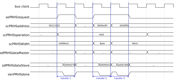
5.2. PRHS Bus Definition . . . 48
5.2.1. PRHS Bus Interface . . . 49
5.2.2. PRHS Bus Protocol . . . 49
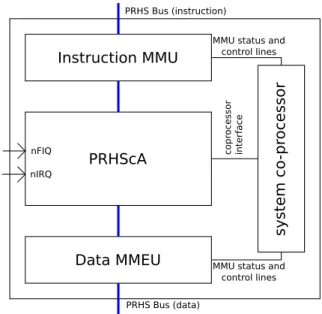
5.3. PRHSpA - PRHS Processor ARM ISA . . . 54
5.3.1. PRHScA - PRHS Core ARM ISA . . . 55
5.3.2. System Co-processor . . . 60
5.3.3. MMU - Memory Management Unit . . . 62
5.4. Base System Devices . . . 62
5.4.1. I/O Devices Fundamentals . . . 63
5.4.2. PRHS Bus Controller - Multiplexing primary and secondary PRHS Bus . . . 65
5.4.3. BusComponentStatus - Managing Device Discovering . . . 67
5.4.4. intchip4prhs - Interrupt Management Device . . . 68
5.4.5. timer4prhs - Timing Measurement in the PRHS Framework . 69 5.4.6. uart4prhs - Basic User Interaction . . . 71
5.4.7. bram4prhs - Block RAM based Memory . . . 72
5.5. PRHS SD Bus Subsystem . . . 73
5.5.1. PRHS SD Bus Definition . . . 74
5.5.2. PRHS Bus to PRHS SD Bus Cache . . . 78
5.5.3. PRHS SD Bus Interconnection System . . . 82
5.5.4. PRHS SD Bus Bridges . . . 86
5.6. Platform Specific Devices . . . 88
5.6.1. pstwo4prhs - Mouse and Keyboard Interfaces . . . 88
5.6.2. sysace4prhs - Compact Flash Card Controller . . . 89
5.6.3. v5emac4prhs - 10/100 Mbit Ethernet Controller for Virtex5 FPGAs . . . 91
5.7.2. reconfIF4prhs - Reconfigurable Module Control Interface . . . 93
5.7.3. Reconfiguration Guard - Address Space Separation and Sen-sitive Signals Gating . . . 94
5.7.4. icap4prhs - internal configuration access port . . . 94
5.8. Composed Hardware Modules . . . 95
5.8.1. base - Basic System . . . 95
5.8.2. baseReconf - Extend Basic System with a PR extension Module 97 5.8.3. baseReconfTop modules - Board Specific Top Modules . . . . 97
6. PRHS Framework - L4PRHS 99 6.1. General Overview on L4PRHS . . . 99
6.2. Processor Specific Adaptations . . . 100
6.3. Machine Specific Adaptations . . . 103
6.4. PRHS Specific Device Drivers . . . 110
6.4.1. Overview on Linux Device Model . . . 110
6.4.2. Block Device Drivers . . . 111
6.4.3. Character Device Drivers . . . 112
6.4.4. Network Device Drivers . . . 114
6.4.5. Partial Reconfiguration Extension related Device Drivers . . . 115
7. PRHS Framework - Software 119 7.1. C Compiler Toolchain . . . 119
7.2. PRHS Bootstrapping . . . 121
7.2.1. Expected Hard Disk Structure . . . 121
7.2.2. First Stage Boot Loader . . . 122
7.2.3. Second Stage Boot Loader . . . 122
7.3. System Base Software . . . 123
8. Proof of Concept 125 8.1. Hardware . . . 125 8.1.1. Idle Configuration . . . 125 8.1.2. UART Configuration . . . 126 8.1.3. Core Configuration . . . 126 8.2. Device Drivers . . . 127 8.2.1. Idle Configuration . . . 127 8.2.2. UART Configuration . . . 127 8.2.3. Core Configuration . . . 127 8.3. Software . . . 128 8.3.1. Idle Configuration . . . 129 8.3.2. UART Configuration . . . 129 8.3.3. Core Configuration . . . 129
8.4. Proof of Concept in Comparison to Main Idea . . . 130
8.4.1. Processor related Results . . . 130
8.4.4. Machine related Results . . . 133
9. Conclusion 135
9.1. Summary . . . 135 9.2. Future Prospects . . . 136 9.2.1. Thoughts on the Pause, Suspend and Resume Problem . . . . 136 9.2.2. Thoughts on FPGA Design Flows . . . 138 9.3. Application Areas for Reconfigurable Logic based System VMs . . . . 138
Literature 145
A. VHDL Coding Conventions 147
A.1. Signal Naming Conventions . . . 147 A.2. Component Instantiation Conventions . . . 148
B. Devices - Platform Overview 149
1.1. Motivation
In 1965 Gordon E. Moore stated: ”The complexity for minimum component costs has increased at a rate of roughly a factor of two per year.”[Moo65] Over the decades this has been transformed to: ”The number of transistors per area will double every 18-24 months”. The well known Moore’s Law. An also well known deduction is: ”calculation performance doubles every 18-24 month”.
The implication ”calculation performance follows transistor density” was practically achieved by using transistors for a variety of additional hardware features to increase clock speeds of integrated circuits. This approach had been successfully used till the very first years of the 21st century. Today modern processor systems perform with clock speeds between one and up to four GHz. In Figure 1.1 the age before the millenium change is labeled as Age of clock speed. Due to different physical effects the clock speeds are facing the so called frequency wall.
To turn more and more transistors still delivered by the road maps of silicon foundries into performance, the total of cores has been increased on processor de-signs. This fact is considered asAge of parallelism in Figure 1.1. It is easy to predict that the curve of the core will also face its wall due to Amdahls law. Assuming this trend will be stable the next few years, a single chip might hold more than 256 processor cores in a few years. This might be beneficial for supercomputing needs, but for the general purpose computer it is oversized.
Configurable circuits are a promising approach to turn increasing transistor totals into performance. This is denoted in Figure 1.1 as Age of configuration. This re-quires significant changes in operating systems, in the areas of software and system engineering. Traditional approaches were focused on optimizing algorithms to per-form on standard parallel hardware. The configware approach is vice versa in the sense that hardware is now optimized to support algorithms in form of accelerator
units. Todays trend is to use configurable computing to add those accelerator units
to existing computer architectures.
Hence, it is expected that future (configuration age) processors contain a propor-tionate amount of cores, whereas the remaining available transistors are used to form reconfigurable areas. In those areas, the accelerator units can be placed on an
Figure 1.1.: Moore’s Law and the consequences for computer architectures. Memory capacities are scaling directly with Moore’s law. So did the clock speeds
until the very early 2000s. Then physical effects limited the clock speeds to 1-4Ghz. [Kla13] expects the same for the total of cores for the mid range future.
To take profit from a still increasing total of transistors configurable computing seems to be a promising technology. (Figure source: [Kla13])
as needed basis [Kla13].
Another area of interest in computer science are virtual machines (VMs). For desk-top computers, system virtual machines received renewed interest during the last decade. Especially after x86 based processors of Intel and AMD were enabled to sup-port native executed system virtual machines. A system virtual machine allows the execution of one or more guest operating systems while the original host operating system is still running. This approach has several advantages:
Robust systems: A failure of a guest machine doesn’t affect the overall system. Enhanced security: System virtual machines are often called sandboxes in the area
of IT-security to emphasize the ability to separate the guest systems against each other.
Resource utilization: Instead of running multiple computers, which are busy most of the time, virtual machines provide a way to enhance the usage of one phys-ical computer, presented as an illusion of being multiple, occasionally used ones.
Mixed OS platforms If the user of a computer system wants to use different soft-ware, only available for different operating systems, it’s much easier to switch between several guest operating system instead of booting the necessary one every time it is needed.
Multi platform development For a software developer virtual machines provide two advantages: Firstly, a VM can be used to emulate different hardware configurations. The second advantage refers to the fact, that testing software on different (virtualized) operating systems is faster as switching between them by means of shutting one down and booting another one.
Migration Migrating to a new operating system can be tested step by step with-out the need to remove the old operating system from a machine or use an additional machine, only required for the migration period.
1.2. Purpose of this Work
This thesis presents the approach of taking advantage of reconfigurable logic by com-bining it with the idea of virtual machines. This combination allows to instantiate additional hardware resources for virtual machines, in opposition to the emulation approach of conventional virtual machines.
In this thesis, the requirements and dependencies among reconfigurable logic and operating systems are investigated to enable the use of virtual machine mechanisms on systems, combining hard-wired (static logic) and reconfigurable logic. To proof the feasibility of this idea, a proof of concept demonstrator is needed. To implement such a proof of concept demonstrator a testing framework, the Partial Reconfigurable Heterogeneous System (PRHS) framework has been developed. This framework is also presented in this thesis. Finally, the benefits of those reconfigurable logic based virtual machines are discussed in theory and in context of the proof of concept demonstrator.
1.3. Structure of this Work
This thesis is structured as follows:
In chapter 2 a brief introduction on (re)configurable computing will be given. Conventional virtual machines will be briefly introduced in chapter 3. This is neces-sary to define a common terminology, as the term virtualization is extensively used in computer science in different senses. Additionally, this chapter is the basis for the theoretical and practical evaluation of the main idea of this thesis.
In chapter 4 the main idea of this thesis will be shown in detail. This includes the deduction of requirements for reconfigurable logic based virtual machines and also a discussion on the theoretical benefits.
In chapter 5, 6 and 7 the developed PRHS framework will be presented. Due to it’s complexity, the hardware, operating system and software parts of the PRHS framework are presented in separate chapters.
The PRHS framework is used to implement a proof of concept demonstrator, as will be shown in chapter 8. This demonstrator is used to show the applicability of reconfigurable logic based system virtual machines.
Chapter 9 summarizes the results of this thesis and gives future prospects regarding the main idea of this thesis.
According to [CH02] (re)configurable computing is intended to fill the gap between hardware and software, achieving potentially much higher performance than
soft-ware, while maintaining a higher level of flexibility than hardware. Therefore, an
overview about the principle mechanisms of (re)configurable hardware is presented in this chapter. Focus lies on Field Programmable Gate Arrays (FPGAs) because they are todays most flexible reconfigurable devices and are in central scope of this thesis.
2.1. Configurable Hardware
Without elaborating too much details, each piece of hardware can be classified into storage elements, like Latches and Flip-Flops, as well as combinational circuits,like gates. By combining those elementary elements, larger circuits with more compu-tational functionality can be implemented.
Configurable hardware summarizes those circuits, whose functionality can be changed after the circuits leave the silicon fabric.
2.1.1. Memory - Look Up Table
A boolean function is a transformation given by
Bm →Bn;B={0,1};m, n∈N
Each boolean function can be implemented by a dedicated combinational circuit. A memory with an address width of m bits and a word width (number of bits per addressable memory cell) of n can implement each of the 2m∗2n possible boolean functions of the form given in the above equation. This can easily be achieved by putting the truth table into the appropriate memory cells.
The following example illustrates this approach. A boolean function of the form:
f(a, b)→(w, x, y, z);a, b, w, x, y, z ∈B={0,1}
is given by the following truth table: a b w x y z 0 0 0 0 0 0 0 1 0 1 1 1 1 0 0 0 1 1 1 1 1 1 1 0
Figure 2.1 shows, how the truth table is mapped into the bits of the memory.
0 0 0 0
0 1 1 1
0 0 1 1
1 1 1 0
addr ess decoder a b w x y z 0 1 2 3 memory cellFigure 2.1.: Truth table mapped into memory.
The contents of a RAM can be altered at runtime and most of today ROMs are also (re)programmable (e.g. EEPROMs). Hence, a memory can be seen as the simplest form of a (user) (re)configurable hardware circuit.
2.1.2. Multiplexers
Look Up Table
The key concept of using a memory as a (re)configurable hardware device is, to put the truth table of the required boolean function into the memory cells. The memories address decoder is used to select the corresponding line of the truth table. This principle can also be achieved by using a multiplexer, where the select inputs correspond to the address bits of the memory and the input lines are the corre-sponding bits of the truth table. As a multiplexer usually only has one output, it is necessary to usen multiplexers in parallel.
Regarding to the example of the previous section, the corresponding multiplexer solution can be found in Figure 2.2.
a b w x y z 0 0 0 1 0 0 0 0 1 0 1 1 1 0 1 1
Figure 2.2.: Truth table implemented by multiplexers.
If the data inputs of the multiplexers are connected to some kind of storing ele-ment (e.g. a Flip-Flop or SRAM cell), this solution can be seen as another kind of (re)configurable circuit for implementing a boolean function.
Shannon Expansion
Another way of utilizing Multiplexers in reconfigurable logic is to take advantage of the Shannon expansion [Sha49] (in the following equation, expansion is about x0):
f(x0, x1, . . . , xn−1) =x0 ∧f(1, x1, . . . , xn−1)∨x0∧f(0, x1, . . . , xn−1)
Applying the Shannon expansion n times for the above equation will result in the disjunctive normal form. This allows to implement the multiplexer look up table solution presented above.
If it is applied onlyn−1 times, the solution is still applicable to multiplexers. The remainingnth literal, that has not been a subject to the Shannon expansion is used as an input to the multiplexer. The other n−1 signals are used as the multiplexer select signals. This approach requires a programmable interconnection matrix, to select the right literals as multiplexer input and select signals.
For the above given example, the results for the solution are given in Figure 2.3.
2.1.3. AND/OR Matrices
According to [HM04], a programmable two-stage AND/OR matrix is the essential component of a Programmable Logic Device (PLD). Such an AND/OR matrix is suitable for implementing boolean functions given in disjunctive normal form. An example for such an AND/OR matrix, implementing the boolean function example of the previous section, is shown in Figure 2.4.
The AND matrix and the OR matrix can be either programmable or are already hard wired when the circuits are leaving the factory. Depending on the possible
0 1 b a 0 1 0 1 0 1 0 1 w x y z programmable matrix programmed connection
Figure 2.3.: Shannon expansion results implemented by multiplexers. Thereby, w is expanded about b;x, y and z are expanded about a.
&
&
&
&
a b≥1
≥1
≥1
≥1
w x y z&
programmable connection and-matrix or-matrix≥1
programmed connectionFigure 2.4.: Example for an AND/OR matrix implementation [HM04].
combinations of programmable/hard wired for the AND and OR matrices, there are three different types of configurable device classes as shown in table 2.11. In-terestingly, memories also fit into this categorization, when the address decoder is interpreted as AND matrix and the memory cells as OR matrix.
2.1.4. Simple Programmable Logic Devices
All the programmable devices mentioned in the previous sections are suitable for implementing boolean functions and therefore can replace dedicated combinational 1If neither AND nor OR matrix are programmable, the device isn’t regarded as configurable at
device class PROM (Programmable ROM), RAM PLA (Programmable Logic Array) PAL (Programmable Array Logic)
AND-matrix hard wired programmable programmable OR-matrix programmable programmable hard wired
Table 2.1.: AND/OR matrix categorization for configurable devices [HM04], [Sca01].
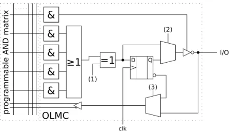
circuits. Still missing is the feature of a storing element like a latch or Flip-Flop to be able to implement finite state machines. In Figure 2.5 an AND/OR matrix is combined with a Flip Flop, several multiplexers and a tri-state gate, forming a so called (output logic) macro-cell (OLMC) of a Simple Programmable Logic Device (SPLD). In addition to the programmable AND-matrix, the pins (1), (2) and (3)
&
≥1
&
&
&
=1
D Q clk (1) (2)&
(3) I/O OLMC pr ogr am ma bl e A ND m at ri xFigure 2.5.: An OLMC example (notional).
are also used for configuring the behavior of a macro cell.
The combination of several such OLMCs with an appropriately sized AND-matrix form a SPLD.
2.1.5. Complex Programmable Logic Devices
Connecting several SPLDs with an interconnection matrix and dedicated input/out-put stages on one chip results in a complex Programmable Logic Device (CPLD) as seen in Figure 2.6.
SPLD
SPLD
SPLD
SPLD
int
er
con
n
ec
tio
n
ma
tr
ix
I/O stage I/O stage I/ O s ta ge I/ O s ta ge Figure 2.6.: A CPLD example [HM04].2.1.6. Programming Technologies
There exist several different programming technologies for CPLDs and FPGAs. (FP-GAs will be introduced in the next section.) The main distinguishing feature for the programming technology is reconfigurability. A programmable logic device is
one time configurable, if it can be programmed only once, after it has left the
sili-con factory. If it is (re)programmable several times, it is called reconfigurable. For the reconfigurable programming technologies, there is an additional distinguishing feature: programming persistence. The programming can either be volatile, if the device has to be reprogrammed after every power down, or non-volatile, if the last programming is still available after a power down of the device. Categorization and corresponding programming technologies are summarized in the following table [HM04]:
category one time configurable non-volatile volatile technology Fuse, Anti-Fuse Flash, EEPROM SRAM
2.2. FPGAs
FPGAs further develop the idea of the CPLDs. Both device classes have an amount of interconnected programmable blocks in common. For Field Programmable Gate Array (FPGA)s this amount is some orders of magnitude higher compared with CPLD. In addition the relation between boolean functions (LUTs) and storage el-ements (Flip Flops) is different for FPGAs and CPLDs. In general, FPGAs have more Flip-Flops in relation to the configurable combinational logic as CPLDs. A FPGA consists of a number of three main elements:
CLB A configurable logic block is the basic element of a FPGA and contains the configurable logic.
I/O-blocks Input-/output-blocks connect the internals of a FPGA to the externals of the chip.
interconnection system The interconnections system connects the CLBs and the I/O blocks with each other. The interconnections are configurable.
The components will be described more detailed in the following subsections.
2.2.1. CLB - Configurable Logic Blocks
The basic element of a FPGA is a so called Configurable Logic Block (CLB). The general structure of a CLB is shown in Figure 2.7.
LUT
i0 i1 in D-FF clk sel outCLB
Figure 2.7.: General structure of a CLB.A CLB consists of a Look-Up-Table (LUT) who’s output might be used as an input to a Flop Flip or as direct output of the CLB. The size of a typical CLB-LUT ranges up to a 6-input LUT on todays FPGAs. The programmable components of the presented notional CLB are the LUT and the select-line of the output multiplexer (marked red in Figure 2.7).
2.2.2. I/O-Blocks
The Input-/Output blocks connect the pins of FPGAs with the internals of the chip. This provides the possibility to configure the pin as an input, as an output or as both of them (tristate, pull-up or pull-down). Additionally, it provides the possibility to wrap the Input/Output voltage levels and technologies (e.g. CMOS or TTL).
2.2.3. Interconnection System
The interconnection system connects the CLBs and I/O blocks of FPGAs. Depend-ing on the technologies, there are three principle possibilities to organize FPGAs as shown in Figure 2.8.
a) b) c)
Figure 2.8.: Organizational structure of a FPGA, a) block oriented, b) line oriented, c) cell oriented [HM04].
block oriented Horizontal and vertical lines connect arrays of CLBs.
line oriented The CLBs are arranged as rows. Between those rows are the horizon-tal connections. Vertical connections are located in a layer above the CLBs. cell oriented There is no CLB-interconnection in the CLB-layer. Horizontal and
vertical connections are located in layers above the CLB-layer.
2.2.4. Additional Elements
In addition to the three main FPGA elements, presented in the previous sections, dedicated hardware components are possible. Common components, also available on todays FPGAs, are Block RAM,Digital Signal Processors (DSPs)and even entire processors (so called hard cores).
FPGA vendors also introduced chips, which include reconfigurable areas with an entire system on chip. (e.g. Zynq[Xil12b])
2.2.5. Dynamic and Partial Reconfiguration Capabilities
Early FPGAs and the corresponding work-flows only allowed to (re)configure the entire FPGA. As next development step,partial reconfiguration was developed, al-lowing only parts of the FPGA to be reconfigured, without touching the remaining parts.
Concerning those remaining parts, two possibilities arise, in how they are handled while the partial reconfiguration (PR) takes place. The static partial reconfigura-tion approach ”freezes” the remaining parts of the FPGA, whereas the dynamic
partial reconfiguration approach allows the remaining parts to keep running when
the reconfiguration process takes place.
If the reconfiguration process is initiated and performed by the remaining part, a
in-system dynamic and partial reconfiguration takes place.
2.3. Reconfigurable Logic in Computer Architectures
Besides the solely usage of a FPGA (e.g. for rapid prototyping), it is usually used within a computer architecture. Starting with the simplified system view of Figure 2.9 different possibilities exist, where to place reconfigurable logic and for what purpose to use it.
CPU(s)
Memory(ies)Device(s)
Figure 2.9.: A simplified system overview on a computer architecture.
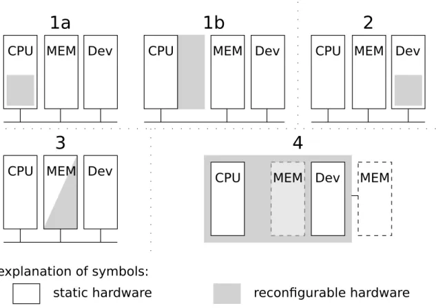
Figure 2.10 gives a summarized overview on the different possibilities how to use reconfigurable logic in a computer architecture. Parts of a system, which are not reconfigurable at all are summarized as static hardware. Further discussion will be done in the subsequent sections.
2.3.1. CPUs and Reconfigurable Logic
This section is related to variant 1a and 1b of Figure 2.10. Variant 1a integrates reconfigurable logic into a processor itself. This results in the possibility to change the number of functional units (ALU, Multiplier, etc.) for super-scalar or VLIW architectures at runtime. Another possibility is to change the ISA of the processor itself at runtime. [Raz94], [NZ04] and [HK09] are academic examples for variant 1a).
Variant 1b provides mechanisms to reconfigure additional processing units (co-processors or (co-processors) besides the static (co-processors. The Convey HC-1 series
CPU MEM Dev CPU MEM Dev CPU MEM Dev
CPU MEM Dev
static hardware reconfigurable hardware
explanation of symbols:
CPU MEM Dev MEM
1a
1b
2
3
4
Figure 2.10.: Variants for including reconfigurable logic into a computer architecture.
(industrial), [HW97] and [Dal99] (academic) are examples, using the co-processor extension mechanism.
Architecture variant 1b is also referenced in literature as tightly coupled reconfig-urable logic.
2.3.2. Devices and Reconfigurable Logic
This section is related to variant 2 of Figure 2.10. The term device isn’t necessarily limited to I/O devices. Also function units, that are accessible as memory mapped or port mapped devices (in difference to variant 1b) are covered by this term. Convey HC-2 series (industrial) and several academic examples (e.g [HH09] or [PP04]) are based on this architecture variant.
This architecture variant is also referenced in literature as loosely coupled reconfig-urable logic.
2.3.3. Memories and Reconfigurable Logic
This section is related to variant 3 of Figure 2.10. As CPU and devices have been investigated for their suitability to use reconfigurable logic among them, memories are investigated in this section.
In general two possibilities arise. The first one is to use reconfigurable logic to im-plement memory cells in it’s pure sense. The second one is to provide reconfigurable logic besides the memory cells.
Reconfigurable Logic as Memory
CLBs, consisting of Flip-Flops and LUTs are presented as central element of FPGAs in section 2.2. The Flip-Flops can be used to form memory cells, the LUTs can be used to instantiate encoding and decoding logic. Hence, memory functionality can be configured into reconfigurable logic.
This approach is extremely resource intensive and even the most modern FPGAs can only form a size limited memory of just a few MByte.2 For this reason the FPGA
vendors started to include dedicated memories (Block RAM) into their FPGAs to get on chip memory at low area costs.3 In summary, FPGAs are not suitable to instantiate large amounts of memory.
Reconfigurable Logic as Memory Supporting Elements
If a memory shall not only hold data, but implement some kind of intelligence, as it is for content addressable memory (CAM, also knwon as associative storage), another possibility to take advantage of reconfigurable logic exists. For a RAM, one ask for data at a given address. For a CAM, it’s the other way around, one asks for the addresses, where specified data can be found. For this reason, CAMs are more complex than RAMs, as they have to include pattern matching and search algorithms in hardware. For a more detailed introduction on CAMs see [PS06]. It is imaginable to instantiate those pattern matching and search algorithms of CAMs in reconfigurable logic and therefore reduce the corresponding area consump-tion as those algorithms can be (re)configured as needed. The idea of implementing CAMs on FPGAs has been described and implemented by several authors like in [UKJCC12] or [GLD00].
2The current largest FPGA of Xilinx (XC7VX1140T) can form 2.2 MB of distributed RAM, if it is used entirely as memory. (See current FPGA family product overviews)
3The current largest FPGA of Xilinx (XC7VX1140T) contains 8.5 MB of Block RAM. (See current FPGA family product overviews)
2.3.4. Static Islands beside Reconfigurable Logic
This section is related to variant 4 of Figure 2.10. In opposite to variants 1 to 3, where reconfigurable logic is used to support static logic, variant 4 turns the principle upside down. On a reconfigurable chip, dedicated (not reconfigurable) hardware is added next to reconfigurable logic. Regarding processors, they are called hard-cores. Examples are Xilinx FPGAs including a PowerPC core.
Additionally, dedicated I/O device logic can be added to the reconfigurable chip. Zynq series of Xilinx [Xil12b] or Altera SoC-FPGAs [Cor13] are examples, where hard-cores and dedicated I/O device logic are integrated onto a chip, who’s remain-ing area is used as reconfigurable logic.
As already discussed in the previous section, reconfigurable logic is not suitable to implement large amounts of memory. Therefore, these architectures usually provide dedicated external memory. The memory controller itself may reside on the FPGA.
2.3.5. Extensions and Combinations
In the previous subsections different approaches of combining reconfigurable logic with conventional computer architectures have been discussed. Combinations of those variants are also possible. The presented variants are all limited to single computers. Extension to multi-computer systems like clusters are also possible and have already been implemented, like the Cray XD1 ([cra04] and [UHT]) (industrial) or Axel Cluster [TL10] and RAMPSoC [GHSB08] (academic).
The concepts of virtualization and virtual machines are widely and extensively used mechanisms in computer science as they provide platform independence, effective resource sharing and security by isolation. They are also part of the main idea of this thesis.
Before starting a discussion about virtual machines, the term machine has to be defined. The meaning is dependent on the perspective.
From the perspective of a process, a machine consists of a logical memory address space, assigned to that machine, along with user level-registers (of the processor) and instructions that allow the execution of program code, associated with the process. I/O is only visible for a process through an operating system. Therefore, for a process a machine is constituted by the underlying hardware, the operating system and additional software providing necessary interfaces for the process (see Figure 3.1a). Hardware OS Virtualizing software Application process Process virtual machine Application process Guest Runtime Host Hardware OS Virtualizing software Application process Guest VMM Host System virtual machine OS Application process
a)
b)
Figure 3.1.: Process and System virtual machines [SN05a].
From the perspective of an operating system, an entire system runs on an underlying machine. The system is an execution environment for applications (processes), man-aging the sharing of the available hardware resources between those applications. Hence, the machine is defined by the underlying hardware characteristics alone (see fig 3.1b).
For these given reasons, there are two types of virtual machines in general: process virtual machines and system virtual machines. A process VM exists to execute a process. The (process) machine is constituted by hardware, operating system and an optional virtualization software. A system VM provides a complete environment to execute a (guest) operating system. The system machine is constituted by hardware and a virtualization software.
The virtualizing software, that implements a process VM, is often termed runtime
software. The virtualizing software in a system VM is typically referred to as the
Virtual Machine Monitor (VMM).
This chapter is based on verbatim excerpts and summaries of [SN05b] and [SN05a].1
3.1. Process Virtual Machines
Process VMs provide a virtual programming interface (application programming interface (API) and standard libraries) for user applications.
3.1.1. Operating Systems
Operating Systems (OS) are the oldest form of process virtual machines. They give each process the illusion of having a complete machine for their own. The OS supports this illusion by managing resources (processor(s), devices, memory) and enforce time-sharing of theses resources among the different processes. In conse-quence an operating system provides a replication of the underlying hardware for each concurrently executed program. If the operating system is regarded as process virtual machines host, there is no need for a dedicated virtualization software. The OS itself is the virtualization software in this case.
3.1.2. Emulators and Dynamic Binary Translators
A challenging problem occurs, if a program shall be executed on machine that has a different ISA than the intended ISA, this program was originally compiled for. The ISA of the program has to be emulated by the process executing environment.
Interpretationis a straightforward way to implement this emulation. The interpreter
program fetches, decodes, and emulates (almost each single) instruction of the guest ISA. This process is very slow, as emulating one instruction of the guest ISA might require several host ISA instruction.
Dynamic binary translationis an approach to speed up the translation process by not
translating the guest program instruction by instruction, but on the basis of blocks of consecutive instructions. By saving already translated blocks, and re-using them if necessary, the relatively high overhead of translation can be reduced.
3.1.3. Same-ISA Binary Optimization
Dynamic binary translation, as described above, can include code optimization to reduce performance loss. This capability enables to implement VMs, wherein the guest and host ISA are the same, with optimization of a program as a VM’s sole purpose. Same ISA dynamic binary optimizers use profile information collected during the interpretation or translation phase to optimize the binary executable on-the-fly.
3.1.4. High-Level-Language VMs
A key object for process VMs is cross-platform portability. Ifm∈Nprograms have to be used onn ∈N different (operating) systems, several problems occur:
• Different operating systems use different system calls and application pro-gramming interfaces (APIs). Therefore, the sources have to be prepared for compiling them for different operating systems.
• m×n compilation steps are necessary to compile each of them programs for all n operating systems.
To solve these time consuming problems, high-level-language VMs have been intro-duced. In summary a new intermediate application programming interface (API) is defined which is used by programs. To allow those programs to be executed on the different operating systems, a run-rime-environment is introduced. The run time environment has to be compiled for each of them targeted operating systems. This is usually done by the run time environment developer, not necessarily the software developers. Each of the n programs have to be compiled for the run time environment without the necessity to differentiate between a lot of APIs.
Examples for Run Time Environments are the Java Virtual Machine or the .net Framework Run Time Environment.
3.2. System Virtual Machines
In a system VM, the VMM primarily provides platform replication. The central issue is dividing a set of hardware resources among multiple guest OS environments. The VMM manages and has access to all the hardware resources. A guest OS and it’s application processes are then managed under hidden control of the VMM. For this reason, the relationship between the VMM and a guest OS is analogous to the relationship between an operating system and an application in a conventional
system. In the latter, the OS typically works in a privilege level higher than the one of the applications (e.g. system-mode vs. user-mode of the processor), as shown in Figure 3.2 b). A virtual machine system, in which the VMM operates in a privilege
Hardware OS Hardware VMM Hardware Host OS Hardware Host OS Applications Guest OS Guest Apps VMM Guest OS Guest Apps VMM Guest OS Guest Apps Privileged modes Nonprivileged modes a) Traditional uniprocessor system b) Native VM system c) User-mode hosted VM system d) Dual-mode hosted VM system
Figure 3.2.: Native and Hosted VM systems [SN05b].
mode higher than the mode of the guest virtual machine, is callednative VM system. In literature, native VM systems and especially the VMM are also known asType 1
Hypervisor (see [Tan07]).
In ahost VM system the VMM is built upon the already available functionalities of
a host operating system. Whether or not the VMM is allowed to run even parts of it (e.g. in form of device drivers) in a more privileged mode, there’s a differentiation
into user-mode hosted VM systems and dual-mode hosted VM systems as given in
Figure 3.2 c) and d). Which one to choose mainly depends on the possibility to modify host OS functionality. In literature hosted VM systems and especially the VMM are also known as either Type 2 Hypervisor or Paravirtualization depending on the applied virtualization techniques (see [Tan07]).
Which system VM type to choose, isn’t a question of preference. The choice mainly depends on the ”features” of the used hardware and especially the used ISA which itself is predominated by the processor. Hence, different virtualization aspects re-lated to processor, memory and devices will be discussed in the following sections. These aspects are important for the later discussion of the main idea of this thesis.
3.2.1. Processor Virtualization
The key aspect of virtualizing a processor lies in the execution of the guest operating system instructions including both, system-level and user-level instructions. As can be easily seen in Figure 3.2, the guest operating system runs entirely in non-privileged mode, regardless if it is a native or a hosted VM. Therefore, system-level instructions (also known assensitive instruction) are of special interest, as the guest OS can’t execute these, but needs to have the perception of doing so.
There are two general ways to virtualize a processor:
Emulation The methods emulation and dynamic binary translation have already been presented in the process VM section. However, they are the only appli-cable methods, if the needed guest ISA is different to the ISA implemented by the hardware.
Even if host and guest ISA would be the same, emulation and dynamic binary translation can be used to replace the sensitive instruction of the guest system with special calls to the VMM, emulating or interpreting these instructions. This is the typical use case for hosted VM systems.
For Type-2 Hypervisors, the replacement is done at runtime. If the replace-ment of sensitive instructions isn’t done at runtime of the guest system, but at compile time, the technique is called paravirtualization. It is only applicable, if the source code of the guest operating system is accessible and modifiable. Direct Native Execution If host and guest ISA are the same, it is imaginable to
execute the guest OS directly ”as is” on the processor running in user mode. However, the problem of dealing with the guest OS’s sensitive instruction remains.
Popek and Goldberg ([PG74]) stated, that direct native execution is only pos-sible, when the set of sensitive instructions is a subset of the privileged
instruc-tions. A privileged instruction is an instruction, that causes a trap if executed
in non-privileged mode. Under this assumption, each natively executed sensi-tive guest instruction will trap to the VMM. The VMM will then emulate the guests sensitive instruction, providing the guest OS the perception of running in a privileged mode.
This ”simple” requirement for virtualizing a processors ISA was not fullfilled for general purpose x86 based desktop computers till 2005, when AMD intro-duced SVM (Secure Virtual Machine) and Intel VT (virtualization technology) [Tan07]. Till this time some sensitive instruction had been just ignored by the processor, when executed in user-mode. Direct native execution is used by Type-1 Hypervisors.
3.2.2. Virtual Memory Virtualization
In a system VM environment, each of the guest VMs has its own set of virtual memory tables. Address translation in each of the guest VMs transforms addresses in its virtual address space to locations in real memory – this real memory would correspond to the physical memory on a native platform; in a VM platform, however, this is not the case. Rather, in a system VM environment, a guest’s real memory address has to undergo a further mapping to determine the address in physical
memory on the host hardware. Note that there is a clear distinction between real memory and physical memory – terms often used interchangeable in other contexts. Physical memory is the hardware memory. Real memory is a guests VMs illusion of physical memory; an illusion supported by the VMM, when it maps a guest’s real memory to physical memory. It is this real to physical mapping that implements the virtualization of memory in a VM system. ([SN05b] section 8.3.1)
Regardless the type of system VM, native or hosted VMM, there are two methods of virtualizing the virtual memory of a guest OS, which depend on the way the corresponding Memory Management Unit (MMU) enforces the implementation of virtual memory:
Virtualizing Architected Page Tables If the architecture of a page table is defined by the ISA, and the operating system and underlying hardware (MMU) coop-erate in maintaining and using it, we talk about architected page tables. In this case, the TLB is maintained only by the hardware and not visible to the OS. In the case of a TLB miss, the MMU ”walks” the page tables to get the appropriate TLB entry, or signal a permission or page fault to the OS.
Virtualizing architected page tables is done by implementing so called shadow
page tables. Accesses to the page table areas of main memory are sensitive
instructions. Hence, each access to a page table has to trap to the VMM (regardless if hosted or native). The VMM has to update the ”real” page tables appropriately. See [SN05b] section 8.3.2 or [Tan07] section 8.3.5 for details.
Virtualizing Architected TLBs On an architected TLB, the TLB is directly man-aged by the operating system. This TLB has to be virtualized now. The VMM has to hold a virtual TLB for each guest and also manage the ”real” TLB. So each TLB access of a guest OS is sensitive now and has to be handled by the VMM (regardless if hosted or native) to keep the virtual TLB copies up-to date and set the real TLB correctly. See [SN05b] section 8.3.3 for details.
3.2.3. Input/Output Virtualization
The proliferation of I/O devices is also a problem for conventional operating systems, which have developed abstractions to support a wide variety of devices and device types. It is possible to adapt many of those techniques for use in system virtual machines.
The virtualization strategy for a I/O device consists of 1. constructing a virtual version of the device and then 2. virtualizing the I/O activity directed at that device.
When a guest system requests to use the virtual device, the request is intercepted by the VMM. The VMM converts the request to a request of the underlying physical device before it is finally carried out.
Virtualizing Devices
The technique used for virtualizing a device depends on whether it is shared and, if so, the way in which it can be shared. Following are the common categories for devices (see [SN05b] section 8.4.1 for more details):
Dedicated Devices Some I/O devices, by their very nature, must be dedicated to a particular guest or at least switched from guest to host on a very long time scale. Examples of dedicated I/O devices are the display, keyboard, mouse and speakers. However, a guest VM request to such a device will trap to the VMM, which can then issue the request. Interrupts of the device will always trap to the VMM, which can hand them over to the dedicated guest VM.
Partitioned Devices For some devices, such as a disk, it is convenient to partition the available resources among the virtual machines. A very large disk, for example, can be partitioned into several smaller virtual disks that are made available to a virtual machine as dedicated device. To emulate an I/O request for the virtual device such as a disk, the VMM has to translate the parameters for the underlying physical device.
Shared Devices Some devices, such as a network adapter, can be shared among a number of guest VMs at a fine time granularity. A request by a guest VM to use the device is translated by the VMM to a request for the physical device through a virtual device driver.
Spooled Devices A spooled device is shared, but at a much higher granularity than a device such as a network adapter. An example of a device that is often spooled is a printer.
Nonexistent Physical Devices Virtualization makes it possible to provide support for virtual devices ”attached” to a virtual machine for which there is no correspond-ing physical device. The device itself is emulated by the VMM.
Virtualizing I/O Activity
On conventional (non-virtualization) operating systems, I/O abstraction is layered, resulting in different activities at the different layers. Therefore, the following levels, where I/O vitualization can take place, exist.
Virtualizing at the I/O Operation Level The privileged nature of I/O operations makes them easy for the VMM to intercept, because they trap in user mode. How-ever, once intercepted, it may be difficult for the VMM to determine exactly, what I/O action is being requested. The VMM has to ”reverse engineer” the multiple issued requests and deduce the complete I/O action a guest VM wants to perform.
Virtualizing at the Device Driver Level If the VMM can intercept the call to the virtual device driver, it can convert the virtual device information to the corre-sponding physical device and redirect the call to a driver program for the physical device. This scheme requires the VMM to have knowledge about the guest operating systems internal device driver interfaces.
Virtualizing at the System Call Level This approach brings the previous one to the boil. Instead intercepting device driver calls, I/O activity may be already intercepted at system call level. The VMM would need system call routines, that shadow the system call routines available to the user (of a guest VM). This is again, a very guest OS specific task, which requires more guest OS internals understanding than just device drivers.
3.2.4. Multiprocessor Virtualization
The previous system VM discussion focuses on uniprocessor system. Another inter-esting area, where system virtual machines are of interest are large shared-memory multiprocessors (SMP). Here, an important objective is to partition the large sys-tem into multiple smaller (multi- or even uni-)processor syssys-tems by distributing the hardware resources, available in the SMP system. Two general possibilities for partitioning can be found:
Physical partitioning The physical resources of one VM are disjoint from the re-sources of the others. This provides a high degree of isolation.
Logical partitioning The underlying hardware resources are time-multiplexed be-tween different partitions and the associated virtual machines. Compared to physical partitioning, resource utilization is enhanced at the cost of hardware isolation benefits.
Both partitioning techniques require software controlled hardware support to enforce the partitioning.
In the previous chapters, (re)configurable computing and virtual machines are pre-sented separately. In this chapter both ideas will be combined. First of all, related work will be discussed. Finally, the main idea of this thesis will be presented, oc-curring problems will be deduced and theoretical solutions for those problems will be shown as well.
4.1. Related Work
This section is dedicated to related work in the area of combining virtualization and configurable logic. For better understanding the differences of the systems and to draw a clear distinction to the main idea of this thesis, it is necessary to emphasize the different interpretations and meanings of the words virtualization
and (re)configuration among the different authors.
4.1.1. FPGA-Ressource Virtualization
A lot of publications (e.g. [HH09] [PP04]) were issued on using a FPGA as an addi-tional hardware resource, such as general purpose I/O resources, but for acceleration purposes. This technique is called virtualization because a device is virtualized by an operating system (device driver), but has to be considered separately from virtual machines.
Another area of interest for researchers is the virtualization of the FPGA itself. A common idea in this field is to introduce an abstraction layer between the hardware description and the targeted FPGAs to make the FPGA design flow more flexible, faster and device independent. Examples are [FP98], [HSE+00] and [MK11].
4.1.2. JOP: A Java Optimized Processor
This section is based on [SKKR11] and [Sch03]. JOP is a hardware implementation of the Java Virtual Machine (JVM) targeted for small embedded systems with
time constraints. It is implemented as a soft core for usage in a FPGA. The main features of JOP are as follows:
1. Fast execution of Java bytecode1 without the need for an Just-In-Time
com-piler.
2. Predictable execution time of Java bytecode. Small core, that fits in a low cost FPGA.
3. Configurable resource usage through HW/SW co-design.
4. Flexibility for embedded systems through FPGA implementation.
Due to the variation in complexity of Java bytecode, not every JVM instruction can be implemented in hardware (e.g. new orinvokestatic). JOPs solution for this problem is to execute only a subset of the bytecode native (on hardware) and trap more complex ones. These complex instructions are then handled by micro programs .
For the JOP project FPGAs have been used to implement a Java processor. It does not use further (re)configuration capabilities of FPGAs as it will be proposed by the main idea of this work. As Java is a process virtual machine (see previous section), the JOP approach is different to the system virtual machine approach of this thesis.
4.1.3. SDVM - Self Distributing Virtual Machine.
The self distributing virtual machine (SDVM) is an adaptive, self configuring and self distributing virtual machine for clusters of heterogeneous, dynamic computing resources [HEW05]. It was designed to feature undisturbed parallel computation while adding and removing processing units from computing clusters by implement-ing a middleware operatimplement-ing system.
This OS provides a unified view of an application onto the underlying changing hardware environment. The SDVM is therefore to be classified as a process virtu-alization platform. This is different to the main idea of this thesis, where system VMs are used.
In [HW08] the authors of the SDVM present the usage of FPGAs to implement a changing hardware environment providing additional capabilities to SDVM. There-fore, it is named SDVMr when used with FPGAs. The reconfigurable logic areas are used in two ways within SDVMr:
• Adopt the available degree of parallelism (number of processing elements), according to the needs of an application and the available FPGA resources. 1The instructions of the JVM
The processing elements are a combination of a processor, Block RAM, a timer and an interrupt controller. Such a single, reconfigurable logic based processing element of SDVMr is not capable of running a full fledged operating system
as it doesn’t provide enough memory. This is an important difference to the proposed main idea of this thesis, as will be presented in the remainder of this chapter.
• Extent already available processing units with special functions (accelerator units). This is just another FPGA resource virtualization method.
4.2. FPGAs as Dynamic Machine Instantiation
Facility
In this section, the main idea of this thesis is discussed. The main idea is to:
Exploit the possibilities of reconfigurable logic to instantiate hardware supported system virtual machines.
This includes the following paradigms:
1. Reconfigurable logic is used on purpose and by principle to instantiate entire machines with the option to run a full fledged operating system on each of those machines. Those instantiated systems can be seen as a guest system in terms of system virtual machine concepts. (instantiation paradigm)
2. All dedicated resources of the overall system are managed by the host oper-ating system (Virtual Machine Manager), as is done by conventional virtual machine managers. This is an essential requirement to see the overall system as virtualization system. (virtualization paradigm)
If the first paradigm is not full filled, a conventional virtual machine is brought onto a FPGA. If the second paradigm is not full filled, two separate and independent systems reside on one FPGA; the only benefit would be the instantiation of one system by the other.
Figure 4.1 gives a simplified overview on the presented idea:
The arising questions, problems and the corresponding possible solution are dis-cussed in the following.
CPU MEM Dev
static host hardware
CPU
MEM
Dev
reconfigurable guest hardware
instantiation
supervison
host OS guest OS
Figure 4.1.: Simplified overview on the main idea.
4.2.1. Number of Guest Systems
The number of guest systems is generally not limited. Limitations arise from the size of the available reconfigurable logic area and the area required for instantiating a guest machine.
Additionally, the formulated idea is recursive by principle. Recursion depth also depends on the available reconfigurable logic area.
4.2.2. Memory Issues
Concerning the memory of the guest machine, some questions/problems arise: 1. How much memory is needed by the guest system? Can this amount of memory
be provided by the reconfigurable area?
2. How is the virtualization paradigm of the main idea (all resources are managed by the host operating system) enforced for the guest’s memory?
These questions and possible solutions are discussed in detail in the following.
Providing enough Physical Memory for the Guest System
In section 2.3.3 the instantiation of memory in reconfigurable areas has been dis-cussed. It has been stated, that it isn’t reasonable to use reconfigurable logic to instantiate memory, but use Block RAM, also provided by todays FPGAs. If the Block RAM (or to be more precise, the resulting available amount of memory), usable in the reconfigurable area is sufficient for the guest system, no additional
memory resources have to be provided externally to the reconfigurable area.
For most embedded operating systems this assumption might hold. For full fledged desktop or server operating system the few MBytes of Block RAM, embedded in FPGAs, will not be sufficient to even hold the operating system in memory solely. Therefore, it is recommended to provide the possibility of accessing the overall sys-tems main memory to the guest system. From a traditional computer architectures perspective, this can be regarded as a dedicated DMA channel of the reconfigurable area.
A single shared memory controller can be a performance bottleneck for the host and several instantiated guest machines. Hence, it would be beneficial if the over-all system provides more than one memory controller. The specific number is an engineering trade-off depending on the expected average number of guest systems running simultaneously.
Relation between the Host Operating System and Guest Memory
After the guest hardware is instantiated, the guest operating system needs to be started. Before it can be started, it has to be loaded to the appropriate position in the guest systems memory. This can either be accomplished by the host operating system or some kind of guest boot-loader executed on the guest processor.
Nevertheless, guest OS or boot-loader have to get into the guest machines mem-ory, controlled by the host operating system (to fulfill the virtualization paradigm). For this reason a connection between the host hardware and the guest memory is necessary to enable the host system to load software into the guests memory.
1. In the case of a shared main memory, this connection exists by design.
2. In the case of Block RAM based memory, embedded in the reconfigurable area, a dedicated connection between host system bus and this memory has to exist.
Guest Virtual Memory Virtualization
Up to now memory in it’s physical hardware representation has been investigated. Operating systems support virtualization of physical memory for giving an applica-tion the percepapplica-tion of having it’s own memory. This virtual memory concept has to be supported by both - guest and host operating system.
Based on the above given arguments, a memory, accessible by both - the guest and host system is assumed in the following. It doesn’t matter if this is the overall
system memory or a memory, embedded in the reconfigurable logic area(s).2
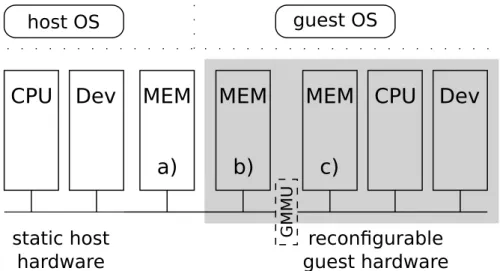
Approaches to virtualize virtual memory are constituted in section 3.2.2 including the differentiation of virtual, real and physical memory. On conventional system virtual machines, the real to physical mapping for the guest VM is enforced by the same Memory Management Unit(s), as host OS and guest OS are executed on the same processor(s). (See [SN05b] chapter 8.3. for further details.) As opposed to this, on virtualization systems, following the main idea of this thesis, host OS and guest OS run on different processors (as a consequence of paradigm 1). Hence, other mechanisms to implement real to physical memory mapping for guest systems are necessary. To support this mapping, additional hardware, the Guest Memory
Management Unit (GMMU) is introduced, as shown in Figure 4.2.2.
CPU Dev
static host hardwareCPU Dev
MEM
reconfigurable guest hardware host OS guest OS GM MUMEM
MEM
a)
b)
c)
Figure 4.2.: Introducing a Guest Memory Management Unit (GMMU). The memory can be the physical main memory of the overall system (a) or a memory instantiated in the reconfigurable area itself (b). Memory c) is not accessible by the host system, because it’s behind the GMMU from the host’s perspective. Therefore, memory c) is not subject of virtual memory virtualization.
The newly introduced GMMU can either be given in the static hardware part of the overall system (only if no reconfigurable logic based, host accessible memory is used; Figure 4.2.2 b)), or be instantiated in reconfigurable logic. If instantiated in static logic, the used interface and protocol for the guest machine’s system bus is fixed. If the GMMU is instantiated in reconfigurable logic, the guest machine’s system bus isn’t fixed at all, providing more flexibility for the guest machine’s characteristics. The implementation complexity depends on the way, the real memory of the guest system is constituted in physical memory. For the further discussion, the following 2The discussion is presented with one guest system. The presented solutions would also apply to
assumptions are made to rely on the essentials of the proposed solutions:
1. The real and the physical address space for the memory of a system is con-tiguous.
2. The real and the physical address space for the memory of a system starts at address 0.
Both assumption can easily be resolved. The latter one by introducing an offset for the start address. The former one by replicating the presented solutions for each separate memory area.
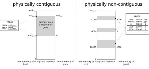
In general, there are two possibilities to solve the problem of translating a guest’s real addresses to the physically associated ones, as shown in Figure 4.3 and further explained in the following. Both solutions are adapted solutions of the real to physical mapping problem for multiprocessor virtualization as presented in [SN05b] chapter 9. = physical memory real memory of host startguest endguest memory area allocated for guest real memory of guest 0 endphys 0 endreal startguest endguest GMBR GMLR GMMU =physical memory real memory of host real memory of guest 0 endphys 0 1000 3000 20000 34000 3C000 0 34000 real
addressphysicaladdress size/type 1000 20000 3000 3C000 1 2 1 GMMU
physically contiguous physically non-contiguous
Figure 4.3.: Options to solve the problem of translating a guest’s real addresses to the physically associated addresses.
contiguous chunk of memory This solution assumes the physical memory associ-ated with the guest system to be contiguous. This assumption allows the GMMU to be very easy and straightforward. It just contains two registers, defining the first (Guest Memory Base Register, GMBR) and last address (Guest Memory Limit Register) of the physical memory area to be used by the guest system. For its simplicity its convenient to be implemented in re-configurable logic.
page based chunks of memory (non-contiguous) The contiguous chunk of mem-ory solution lacks some problems because of it’s simplicity. There is no
de-pendency regarding the MMU of the host system. Hence, the memory area, associated with the guest system mustn’t be swappable by the host system. Additionally, no differentiation regarding memory protection is possible, for example to mark some regions of the guest’s memory as read only for the guest. This would be possible by introducing a GMMU, that can be seen as an ex-tension of the host’s MMU (part of the host machine’s CPU). Therefore, the GMMU has to implement the same memory management mechanisms as the host MMU. For this host ISA dependency and their complexity it is more suit-able to implement this type of GMMU in the static hardware part of the overall system. Nevertheless, it can also be implemented in reconfigurable logic. A GMMU based on this solution operates similar to an Input/Output Memory
Management Unit (IOMMU) used in todays processors (see [ByMK+06] for
an introduction on IOMMUs).
4.2.3. Device Issues
In this section, device virtualization related questions are discussed. As a starting point, devices are classified into two categories:
System vital, non sharable devices: These devices are essential for the function-ality of the host or a guest system. Hence, sharing of such devices is usually senseless, as for example for an interrupt management controller.
Sharable devices: All other devices.
For the presented main idea, only shareable devices are of interest for further discus-sion. A discussion about devices is a discussion about interfaces. In the following, a device is assumed to be physically structured as given in Figure 4.4.
device controller glue logic pure I/O interface system bus interface controller interface
Figure 4.4.: General structure of a device. A device has three interfaces:
• A system bus interface for connecting a device to the processor (via the system bus).
• A controller interface for providing a common interface and protocol for a device on a logical level, that is independent to the system, a device shall be connected to.
• A (pure)I/O interface, representing the ”analog” wires of a device. (For an RS-232 device these are the Tx, Rx and control lines. For a hard disk, these
are the wires connected to the mechanical parts (e.g. rotors)).
A device controller’s task is to transform and interpret the controller interface (and protocol) to I/O interface signals. Glue Logic’s task is to transform the machine specific system bus interface and protocol to the controller specific interface and protocol.
At this point two questions arise:
1. Which interface should be shared between guest and host system? 2. How is this sharing implemented?
Interface Sharing
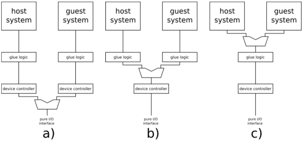
As a device has three different interfaces, three levels of device interface sharing are imaginable, as explained by referencing Figure 4.5:
device controller pure I/O interface host system guest system glue logic device controller glue logic device controller pure I/O interface host system guest system
glue logic glue logic
device controller pure I/O interface host system guest system glue logic
a)
b)
c)
Figure 4.5.: Levels of sharing device interfaces a) shared pure I/O interface; b) shared controller interface; c) shared system bus interface.
shared pure I/O interface If the I/O interface itself is shared between host and guest machine, two device controllers need to be instantiated, resulting in unnecessary area consumption, whether or not these device controllers are instantiated in static or reconfigurable logic. This possibility is therefore only recommended for machines which use the same I/O interface but need different device controllers.
shared controller interface This solution implies the instantiation of two glue logic blocks. This is required, if guest and host machine implement different system buses.
where host and guest implement identical system buses to avoid unnecessary duplication of glue logic.
All three levels of sharing are possible. For the main idea of this thesis, the shared controller interface (Figure 4.5b)) variant is recommended due to the following rea-sons:
1. Assuming that enough I/O lines are available, there is no need to use the same lines in a different fashion (by using different device controllers). Additionally, taken into care the virtualization paradigm, the device provided to the guest should be the ”same” as used by the host machine. ”Same” is related to a device’s behavior implemented by the device controller. Hence, the shared pure I/O interface solution (Figure 4.5a) is not recommended. Furthermore, most devices provide only the device controller interface. For those devices the shared pure I/O interface solution isn’t applicable at all.
2. The main idea of this thesis strongly implies the possibility to instantiate a guest system bus different to the host’s one. The shared system bus interface solution (Figure 4.5c) doesn’t allow this, as there is only one glue logic element, providing one system bus interface.
Organizing Device Sharing
Another question concerning device sharing is, where to place the different parts of a device, in static or in reconfigurable logic?
The subsequent can be seen as a general rule:
1. All parts, that are used/needed by guest and host in the same way and there-fore are physically identical, shall be implemented in static logic to reduce reconfigurable area consumption.
2. All parts, that are not used the same way, and therefore are subject of be-ing exchanged/replaced when a switch is necessary, shall be instantiated in reconfigurable logic.
Following the recommendation of the previous section to prefer interface sharing at the device controller interface level, this implicates:
1. The device controller, is part of the static logic.
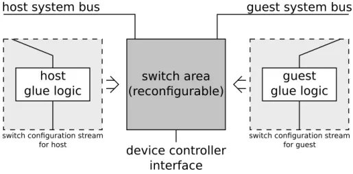
2. The guest systems glue logic shall be instantiated in reconfigurable logic. This prevents the necessity to have a guest system bus interface outside the recon-figurable area. This is important, because guest’s system bus is variable as a consequence of the instantiation paradigm.
![Figure 2.4.: Example for an AND/OR matrix implementation [HM04].](https://thumb-us.123doks.com/thumbv2/123dok_us/9594480.2837288/16.892.194.698.425.756/figure-example-matrix-implementation-hm.webp)
![Figure 2.6.: A CPLD example [HM04].](https://thumb-us.123doks.com/thumbv2/123dok_us/9594480.2837288/18.892.215.672.144.420/figure-a-cpld-example-hm.webp)