Development of a Microcontroller Based Car Speed Controller
Jonathan A. Enokela David O. Agbo
Department of Electrical and Electronics Engineering, Federal University of Agriculture, P.M.B. 2373, Makurdi, Benue State, Nigeria
E-mail of the corresponding author: [email protected]
Abstract
Nigeria and many countries of the world have been experiencing an increase in road traffic accidents much of which can be attributed to human errors such as over speeding. The car speed controller discussed in this work is designed to automatically control the speed of a car so that the car’s speed will not exceed the speed limit that has been set for a particular zone by a regulating body such as the Federal Road Safety Commission (FRSC) in Nigeria. The car speed controller operates by taking inputs from a set of three switches that can set speed limits in kilometers per hour of 40, 80, and 120 respectively. Each setting of the switch is compared with the actual speed of the car that is derived from the car’s speedometer. If the speed of the car exceeds the setting, an actuator is called into operation such that the car’s speed is not allowed to exceed the set limit for the zone. A microcontroller was programmed to take inputs from the switches and the speedometer; depending on the settings the microcontroller turns on light emitting diodes (LEDs) and displays appropriate messages on the screen of a liquid crystal display (LCD). In the simulation model a stepper motor was controlled by the microcontroller through a motor driver to represent the adjustment of speed in the real environment. The program for the microcontroller was written using mikroC development environment and hardware simulation was carried out with the aid of Proteus Design Suite Version 8.0. The speed settings for a zone can be altered to suite the choice of a regulatory agency. The installation of the car speed controller in vehicles will not only give early warnings to drivers but will prevent over speeding thus leading to the reduction in cases of road traffic accidents.
Keywords: Car Speed Control, Speed Governor, Microcontroller, Road Safety
1. Introduction
Nigeria and the generality of the countries in the world lose a great number of their citizens in cases of road traffic accidents every year (Omidiji & Ibitoye 2010). The report by the Federal Road Safety Commission (FRSC) of Nigeria in 2013 shows that as much as 32% of all accidents that occurred that year were attributed to speed related issues (Federal Road Safety Corps 2013). Different types of technologies have been deployed over the past three decades with a view to controlling the speed of automobiles in order to reduce the cases of fatal accidents. Akihiko et al. (1990) patented an automatic car speed controller whose driving circuit is operated by the difference between the actual car speed and the memorized car speed; the difference signal is used to operate an electromagnetic clutch. A similar system is also reported in Akihiko et al. (1992). The systems discussed in Akihiko et al. (1990) and Akihiko et al. (1992) have been rendered obsolete by newer and improved car manufacturing technologies. More modern systems that use electro-hydraulic braking systems and electronic control of throttles are reported by Santoshi et al. (2015), Eswaramoorthy & Araunkumar (2014), and Saivignesh et al. (2015).
Bianco et al. (2013) used the notation of the Unified Modeling Language (UML) to theoretically model a car speed regulator. An electronic system to control car speed using two variable resistors for generating speed control signals that are processed and transformed into a digital signal for controlling the driving speed of an electric car is discussed in the work by Byum (1998). A system that uses the Radio Frequency Identification (RFID) for identification of traffic signals on the road and also for infrastructure to vehicle communication is reported by Perez et al. (2010). This elaborate system not only controls the speed of vehicle and shows its
10
operate the braking or the throttling of the car; this aspect is however successfully simulated in the work using a dc motor. The system uses visual indicators i.e. light emitting diodes (LED) and writes messages on the screen of a liquid crystal display (LCD) to alert the driver of the necessity to stay within prescribed speed limits. An audible alarm is also triggered when the driver exceeds the speed limit. The system described in this work is simple to operate and is also much cheaper than the other systems that have been earlier described in the literature review.
2. Materials and Methods
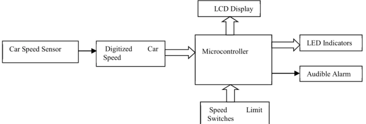
The block diagram of the system is depicted in figure 1. The inclusion of a microcontroller into the system makes it to be a stand-alone type of system that is capable of taking decisions to keep the system functioning properly. The microcontroller receives input signals from the speed limit switches and the digitized actual car speed. In this work three switches are used to set the speed limits at 40 km/hr, 80 km/hr, and 120 km/hr. These speed limits may be altered as desired. The actual car speed may be measured by using several methods one of which is the detecting of the pulses generated by the ignition system (Linscott, 2001). A more accurate method involves the use of sensors such as the Hall effect based sensor (Perez et al. 2010 & Vehicle Speed Sensors 2003).
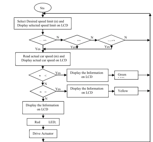
The system operates by comparing the digitized car speed with the value of the speed limit set by the user. Depending on the result of the comparison a decision is taken to light up the appropriate LED and also to write a message on the screen of the LCD. An audible alarm is sounded if the set speed limit is exceeded by the driver. The flowchart of the program executed by the microcontroller is shown in figure 2. This shows that the microcontroller polls the input sensors and depending on their states an appropriate decision is taken after which the microcontroller goes back to monitoring the sensors in a continuous loop.
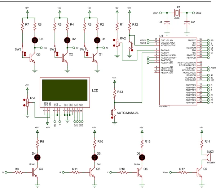
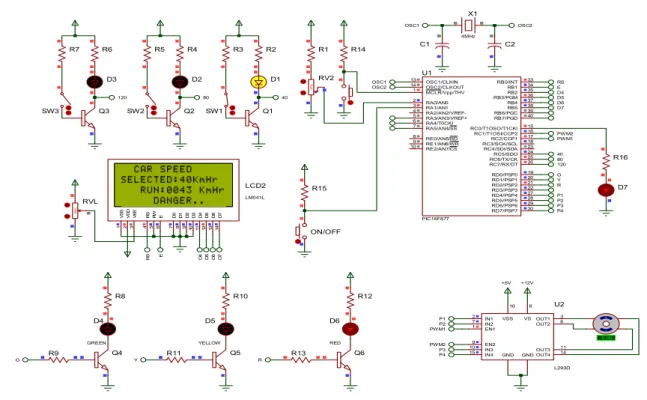
The circuit used for the simulation of the operations of the car speed controller was built in the environment of Proteus Design Suite Version 8.0 (Labcenter Electronics 2014) and is shown in figure 3. A variable resistor RV2 shown in figure 3 is used to represent the actual speed of the car. One of the transistor switches (Q1-Q3) is used for one of the desired speed limits. The microcontroller is programmed to turn on the green, red, or yellow LED as appropriate and to also write a message on the screen of the LCD. An audible alarm system is turned on by the microcontroller when necessary.
Figure 1. Block Diagram of Automatic Car Speed Controller System Car Speed Sensor Digitized Car
Speed Microcontroller LCD Display Audible Alarm LED Indicators Speed Limit Switches
Figure 2. Flowchart of Program for the Automatic Car Speed Controller Yes Yes N o N o N o n=12 Yes Yes Yes N o N o Sta
Select Desired speed limit (n) and Display selected speed limit on LCD
n=40
Read actual car speed (m) and Display actual car speed on LCD
n < n = Green LED Yellow LED Drive Actuator Red LED; n=80
Display the Information on LCD Display the Information on LCD
Display the Information on LCD
12
Figure 3. Schematic Diagram of the Simulation Circuit of the Speed Controller
3. Results and Discussions
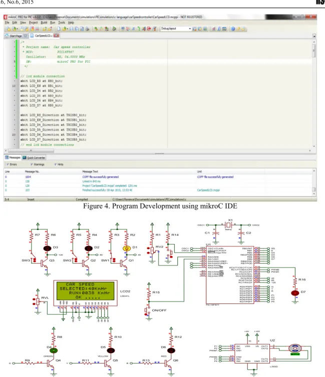
The program for the microcontroller was written in C language and was then compiled into an executable file using the mikroC IDE Version 6.0 (MikroElektronika 2013). A software simulation was carried out with the simulator built into the mikroC IDE to ensure that the program variables and registers changed as desired. The executable file was next imported into the Proteus Design Suite IDE where the hardware circuit shown in figure 3 was constructed and simulated. The program development in mikroC IDE is shown in figure 4. Figures 5 and 6 show the simulation results for the case where the car speed is less than the set speed limit and another where the car speed is greater than the set speed limit, respectively. Table 1 shows the three possible conditions of the set speed switches and the outputs of the microcontroller. Upon successful completion of the software simulation, the system’s hardware was constructed on a vero board and hardware simulation was further carried using MPLAB ICD 2 In-Circuit debugger (Microchip Technology Inc. 2006). The process is shown in figure 7.
1 1 % RV2 C1 C2 OSC1 OSC2 Q1 40 Q2 80 Q3 120 Q4 Q5 G R +5V SW2 SW3 D4 Green D5 Red RA0/AN0 2 RA1/AN1 3 RA2/AN2/VREF-4 RA4/T0CKI 6 RA5/AN4/SS 7 RE0/AN5/RD 8 RE1/AN6/WR 9 RE2/AN7/CS 10 OSC1/CLKIN 13 OSC2/CLKOUT 14 RC1/T1OSI/CCP2 16 RC2/CCP1 17 RC3/SCK/SCL 18 RD0/PSP0 19 RD1/PSP1 20 RB7/PGD 40 RB6/PGC 39 RB5 38 RB4 37 RB3/PGM 36 RB2 35 RB1 34 RB0/INT 33 RD7/PSP7 30 RD6/PSP6 29 RD5/PSP5 28 RD4/PSP4 27 RD3/PSP3 22 RD2/PSP2 21 RC7/RX/DT 26 RC6/TX/CK 25 RC5/SDO 24 RC4/SDI/SDA 23 RA3/AN3/VREF+ 5 RC0/T1OSO/T1CKI 15 MCLR/Vpp/THV 1 U1 PIC16F877 SW1 Alarm 120 80 40 RS E D4 D5 D6 D7 G Y R D 7 1 4 D 6 1 3 D 5 1 2 D 4 1 1 D 3 1 0 D 2 9 D 1 8 D 0 7 E 6 R W 5 R S 4 V S S 1 V D D 2 V E E 3 LCD 5 0 % RVL +5V +5V D 7 D 6 D 5 D 4 E R S D1 D2 D3 +5V AUTO/MANUAL +5V P1 P2 R1 R3 R5 R7 R6 R4 R2 R8 R10 R9 R11 R12 R13 P3 P4 Q6 Y D6 Yellow +5V R15 R16 Q7 Alarm +5V R14 R17 BUZ1 BUZZER
Figure 4. Program Development using mikroC IDE
Figure 5. Simulation Result for Car speed less than the set speed limit
15% RV2 X1 4MHz C1 C2 OSC1 OSC2 OSC1 OSC2 Q1 40 Q2 80 Q3 120 Q4 Q5 G Y SW2 SW3 D4 GREEN RA0/AN0 2 RA1/AN1 3 RA2/AN2/VREF-4 RA4/T0CKI 6 RA5/AN4/SS 7 RE0/AN5/RD 8 RE1/AN6/W R 9 RE2/AN7/CS 10 OSC1/CLKIN 13 OSC2/CLKOUT 14 RC1/T1OSI/CCP2 16 RC2/CCP1 17 RC3/SCK/SCL 18 RD0/PSP0 19 RD1/PSP1 20 RB7/PGD 40 RB6/PGCRB5RB4 393837 RB3/PGMRB2 36 35 RB1 34 RB0/INT 33 RD7/PSP7 30 RD6/PSP6 29 RD5/PSP5 28 RD4/PSP4 27 RD3/PSP3 22 RD2/PSP2 21 RC7/RX/DTRC6/TX/CKRC5/SDO 2625 24 RC4/SDI/SDA 23 RA3/AN3/VREF+ 5 RC0/T1OSO/T1CKI 15 MCLR/Vpp/THV 1 U1 PIC16F877 SW1 PW M1 120 80 40 RS E D4 D5 D6 D7 G Y R D 7 14 D 6 13 D 5 12 D 4 11 D 3 10 D 2 9 D 1 8 D 0 7 E 6 R W 5 R S 4 V S S 1 V D D 2 V E E 3 LCD2 LM041L 50% RVL D 7 D 6 D 5 D 4 E R S D1 D2 D3 ON/OFF P1 P2 PWM1 +5V +12V IN1 2 OUT1 3 OUT2 6 OUT3 11 OUT4 14 IN2 7 IN3 10 IN4 15 EN1 1 EN2 9 VS 8 VSS 16 GND GND U2 L293D P1 P2 R1 R3 R5 R7 R6 R4 R2 R8 R10 R9 R11 R14 R15 R16 P3 P4 P3 P4 PWM2 0.00 Q6 R D6 RED R12 R13 PW M2 D5 YELLOW D7
14
Figure 6. Simulation Result for Car speed greater than the set speed limit
Figure 7. Programming the microcontroller and Hardware Debugging Process
1 7 % RV2 OSC1 OSC2 Q1 40 Q2 80 Q3 120 Q4 Q5 G Y SW2 SW3 D4 GREEN RA0/AN0 2 RA1/AN1 3 RA2/AN2/VREF-4 RA4/T0CKI 6 RA5/AN4/SS 7 RE0/AN5/RD 8 RE1/AN6/WR 9 RE2/AN7/CS 10 OSC1/CLKIN 13 OSC2/CLKOUT 14 RC1/T1OSI/CCP2 16 RC2/CCP1 17 RC3/SCK/SCL 18 RD0/PSP0 19 RD1/PSP1 20 RB7/PGD 40 RB6/PGCRB5 39 38 RB4 37 RB3/PGM 36 RB2 35 RB1 34 RB0/INT 33 RD7/PSP7 30 RD6/PSP6 29 RD5/PSP5 28 RD4/PSP4 27 RD3/PSP3 22 RD2/PSP2 21 RC7/RX/DT 26 RC6/TX/CKRC5/SDO 25 24 RC4/SDI/SDA 23 RA3/AN3/VREF+ 5 RC0/T1OSO/T1CKI 15 MCLR/Vpp/THV 1 U1 PIC16F877 SW1 PW M1 120 80 40 RS E D4 D5 D6 D7 G Y R D 7 1 4 D 6 1 3 D 5 1 2 D 4 1 1 D 3 1 0 D 2 9 D 1 8 D 0 7 E 6 R W 5 R S 4 V S S 1 V D D 2 V E E 3 LCD2 LM041L 50 % RVL D 7 D 6 D 5 D 4 E R S D1 D2 D3 ON/OFF P1 P2 PW M1 +5V +12V IN1 2 OUT1 3 OUT2 6 OUT3 11 OUT4 14 IN2 7 IN3 10 IN4 15 EN1 1 EN2 9 VS 8 VSS 16 GND GND U2 L293D P1 P2 R8 R10 R9 R11 R15 R16 P3 P4 P3 P4 PW M2 0.00 Q6 R D6 RED R12 R13 PW M2 D5 YELLOW D7
Table 1. Set Speed Switches Conditions and Microcontroller Decisions
Switches
Conditions Set Car
Speed Limit
Microcontroller Output
S1 S2 S3
H H L 40 km/h Any of Green, Yellow, or Red LED may be turned on depending on actual car speed; Appropriate message is displayed on LCD; Alarm is on and stepper Motor turns 90̊ when car speed is greater than set speed.
H L H 80 km/h Any of Green, Yellow, or Red LED may be turned on depending on actual car speed; Appropriate message is displayed on LCD; Alarm is on and stepper Motor turns 180̊ when car speed is greater than set speed.
L H H 120 km/h Any of Green, Yellow, or Red LED may be turned on depending on actual car speed; Appropriate message is displayed on LCD; Alarm is on and stepper Motor turns 270̊ when car speed is greater than set speed.
Note that in table 1; L = Low Logic Level Signal and H = High Logic Level Signal.
4. Conclusions
The automatic car speed controller system has been designed and implemented using a microcontroller. Due to the few number of components used the system has a high degree of reliability. This fact also makes the system to be low cost thus making it suitable for deployment in developing countries. The system has been designed to be purely advisory to the driver since the control of the throttle or the braking system has not been physically implemented. The successful simulation of this aspect using a dc motor, however, shows the feasibility of its implementation.
References
Omidiji, A.A. & Ibitoye, S.A. (2010), “Crime and Road Crashes Prevention in Public Transportation System in Nigeria: the Case Study of Kwara, Kogi and Ekiti States”, 24th ARRB Conference- Building on 50 years of Road and Transport Research, Melbourne, Australia.
Federal Road Safety Corps, Federal Republic of Nigeria Annual Report (2013), “Road Crash Statistics”, [Online] Available: http://frsc.gov.ng/2013%FRSC%20Annual%20Report.pdf (February 10, 2015) Akihiko, T., Iwaoka, T., Yamaguchi, Y. & Danzaki, T. (1990), “Automatic Car Speed Controller with Detection
of Abnormality of the Electromagnetic Clutch”, United States Patent Number 5014201. [Online] Available: http://www.patents.com/us-5014201.html (December 10, 2014).
Akihiko, T., Iwaoka, T., Yamaguchi, Y. & Danzaki, T. (1992), “Automatic Car Speed Controller”, United States Patent Number 5107947. [Online] Available: http://www.freepatentsonline.com/5107947.pdf (December 10, 2014).
Santoshi, G.V.L., Hima, B.N. & Uma, R.K. (2015), “Intelligent Vehicle Control Based on Identification of Road and Traffic Signal Operated RFID Transponders”, International Journal of Engineering Research and Applications, National Conference on Developments, Advances, and Trends in Engineering Sciences
(NCDATES). pp. 40-45. [Online] Available:
http://www.ijera.com/special_issue/NCDATES/ECE/PART-5/ECE%20120-4045.pdf (February 13, 2015).
Eswaramoorthy, P. & Arunkumar, M. (2014), “Intelligent Vehicle Control Based on Identification of Road Signs by Solar Powered RFID Transponders”, International Journal of Research in Engineering and Technology, 3, 85-89.
16
Kameswari, U.J., Satwik, M., Lokesh, A. & Reddy, G.V. (2011), “A Design Model for Automatic Vehicle Speed Controller”, International Journal of Computer Applications, 35, 19-24.
Paine M. (2008), “Comments on Draft Protocol for Speed-Limitation Devices”, [Online] Available: http://www.mpainesyd.com/idisk/Public/ANCAP%20speed%20limiter%20comments%20mar08.pdf (February 25, 2015).
Carsten, O. & Tate, F. (2005), “Intelligent Speed Adaptation: The Best Collision Avoidance System?”, Proceedings of the 17th Conference on the Enhanced Safety of Vehicles, Netherlands. [Online] Available: http://tinyurl.com/26cfod (February 25, 2015).
Paine, M., Paine, D., Griffiths, M. & Germanos, G. (2008), “In-Vehicle Intelligent Speed Advisory Systems”, [Online] Available: http://www-nrd.nhsta.dot.gov/pdf/nrd-01/esv/esv20/07-0247-w-pdf (January 25, 2015).
Linscott, R. (2001), “Automotive Speed Indicator”, [Online] Available: http://www.circuitdb.com/?p=398 (January 25, 2015).
Vehicle Speed Sensors (2003), [Online] Available: www.jagsthatrun.com/v8-chapters/v8-tpi-speed-sensors.pdf (August 21, 2014).
Labcenter Electronics (2014), Proteus Design Suite Version 8.0. [Online] Available: http://www.labcenter.com/ (October 21, 2014).
Mikroelektronika (2013), mikroC. [Online] Available: www.mikroe.com (October 21, 2014).
Microchip Technology Inc. (2006), MPLAB ICD 2 In-Circuit Debugger. [Online] Available: http://www.microchip.com/DevelopmentTools/ProductDetails.aspx?PartNO=dv164005 (July 19, 2010).