and Object Life Cycles
Ksenia Ryndina1,2, Jochen M. K¨uster1, and Harald Gall2
1
IBM Zurich Research Laboratory, S¨aumerstr. 4
8803 R¨uschlikon, Switzerland
{ryn,jku}@zurich.ibm.com
2Department of Informatics, University of Zurich, Binzm¨uhlestr. 14
8050 Zurich, Switzerland [email protected]
Abstract. Business process models and object life cycles can provide two different views on behavior of the same system, requiring that these models are consistent with each other. However, it is difficult to reason about consistency of these two types of models since their relation is not well-understood. We clarify this relation and propose an approach to establishing the required consistency. Object state changes are first made explicit in a business process model and then the process model is used to generate life cycles for each object type used in the process. We define two consistency notions for a process model and an object life cycle and express these in terms of conditions that must hold between a given life cycle and a life cycle generated from the process model.
Keywords:consistency, business process model, object life cycle, activ-ity diagram, state machine, UML.
1
Introduction
Business process models are nowadays a well-established means for representing
business processes in terms of tasks that need to be performed to achieve a certain business goal. In addition to tasks, business process models also show the flow ofbusiness objects in a process. Complete behavior of business objects is usually modeled using a variant of a state machine called anobject life cycle(see e.g. [5]). Object life cycle modeling is valuable at the business level to explicitly represent how business objects go through different states during their existence.
There are situations where it is beneficial or even required to use both process models and object life cycles. Consider an insurance company that uses business process models for execution and also maintains explicit business object life cycles. Life cycles may serve as a reference to employees for tracking progress of business objects. For instance, in response to an enquiry about the state of a submitted claim, an employee can explain the current claim state to the customer in the context of the entire claim life cycle that shows all the possible states and transitions for claims. Another example is encountered in compliance checking, where existing business process models are benchmarked against best practice models (e.g. ACORD [2] and IFW [4]) given as object life cycles. Given a best T. K¨uhne (Ed.): MoDELS 2006 Workshops, LNCS 4364, pp. 80–90, 2007.
c
practice object life cycle, it is required to ensure that an existing business process model is compliant with it.
When both business process models and object life cycles are used, it is re-quired that these models areconsistent with each other. Inconsistencies can lead to unsatisfied customers or compliance violations. For example, a customer may be discontent if he/she is incorrectly informed about the processing that still needs to be done before his/her claim is settled. On the other hand, inconsisten-cies between an existing process model and a best practice object life cycle lead to compliance violations that can cause legal problems for a company.
Consistency of object-oriented behavioral models, such as scenarios and state machines, has already been extensively studied [9,10,16,18]. However, the re-lation between business process models and object life cycles is not yet well-understood, which makes it difficult to reason about their consistency.
In this paper, we present our approach to establishing consistency of a busi-ness process model and an object life cycle. In Section 2, we introduce subsets
of UML2.0 Activity Diagrams (UML AD) and State Machines (UML SM) [3]
chosen for business process and object life cycle modeling, respectively. In Sec-tions 3 and 4, we describe our proposed solution that comprises a technique for object life cycle generation from a process model and two consistency notions that can be checked using the generated life cycles. Finally, we discuss related work in Section 5, and conclusions and future work in Section 6.
2
Business Process Models and Object Life Cycles
UML AD is one of the most widely used languages for business process modeling. We consider process models in a subset of UML AD that includesaction nodes
andcontrol nodes(decision, merge, fork, join, start1, flow final and activity final nodes). All these nodes can be connected with control and object flows. Input
and output pins are used to model connection points that allow object flows
to be attached to nodes, with the exception of start nodes that may not have outgoing object flows. Each object pin has aninState attribute that allows one to specify the possible states of objects passed through this pin. Data inputs and outputs of processes are modeled using input andoutput parameters. Our experience with case studies has shown that in practice most process models are created using this subset of UML AD. Therefore, currently we do not consider more advanced elements such as loop nodes and parameter sets, and further assume that hierarchy in process models can be flattened. The reader is referred to the UML AD specification [3] for further information about the language.
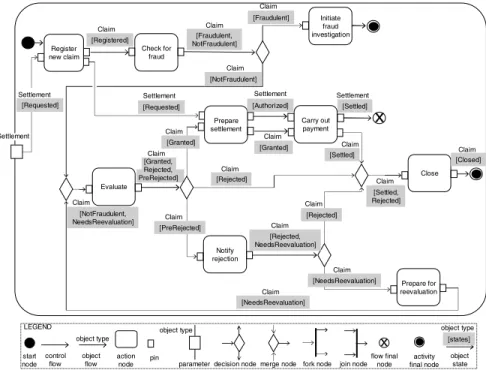
Figure 1 shows an example business process model for a Claims handling
process from the insurance industry that is represented in the chosen subset of UML AD. In this diagram, we can see that theClaims handling process starts when a Settlement in state Requested is received by the process. Next, a new
Claim object is created in state Registered by the Register new claim action.
1
These are calledinitial nodesin UML AD, but renamed here to avoid confusion with
Check for fraud Evaluate Initiate fraud investigation Prepare settlement Notify rejection Prepare for reevaluation Close Claim Claim Claim Claim Claim
Claim [Granted] [Settled] [Fraudulent] [NotFraudulent] [Granted] [PreRejected] [Rejected] [Registered] [Fraudulent, NotFraudulent] [NotFraudulent, NeedsReevaluation] [Authorized] [Settled] [Rejected, NeedsReevaluation] Carry out payment [Settled, Rejected] [Closed] [NeedsReevaluation] Claim [NeedsReevaluation] Claim
x
x object type object type start node control flow object flow actionnode pin parameter decision node merge node fork node join node flow final node LEGEND Claim Claim Claim Claim Settlement Claim Settlement Claim Claim Claim object type object state [states] [Rejected] Claim Register new claim Settlement [Requested] Settlement [Requested] Settlement [Granted, Rejected, PreRejected] activity final node
Fig. 1.Claims handling business process model
TheClaimfurther goes through a number of processing steps that change its state and at the end of the process it is either found to be fraudulent, or it is rejected or settled and subsequently closed.
In Figure 1 we use a slightly tailored graphical representation of the chosen UML AD subset. We indicate object type above an object flow and not above each pin, because we make a simplifying assumption that an object flow can only connect two pins of the same type. We also assume that given two connected object pins (output pin and input pin), the states associated with the output pin are accepted by the input pin, i.e. the set of states of the output pin is a subset of the set of states of the input pin. In Figure 1 we indicate the states associated with the output pin on the connecting object flow.
Associating states with object pins is optional in UML AD, but required in our approach, as this explicit information about object states allows us to establish a relation between a business process model and object life cycles.
For modeling object life cycles, we use a subset of the UML SM language. This subset comprisesstates, with oneinitial stateand one or morefinal states, and
transitions connecting the states. Transitions that are initiated by a particular triggering event can be labeled with atrigger label. As our main application is in a business environment, we choose a simple notation for object life cycles, without considering composite and concurrent states of state machines.
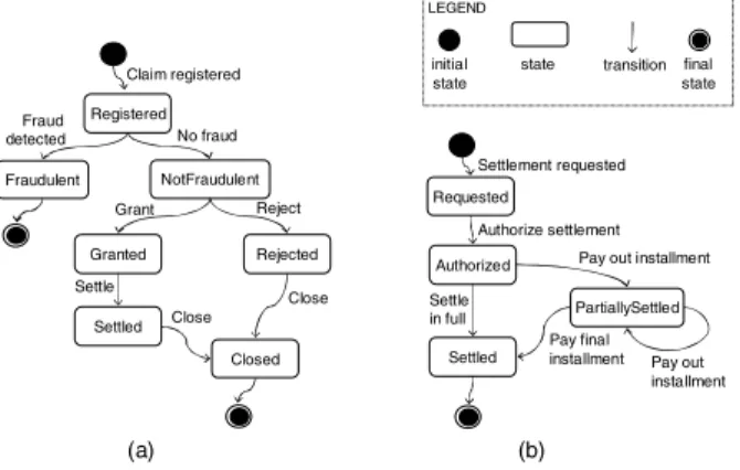
Figure 2 shows two example life cycles forClaimandSettlementobject types. In (a), it can be seen that all objects of typeClaim go through stateRegistered
directly after the initial state and pass through either Fraudulent or Closed
states before they reach a final state. In (b), it is shown that after aSettlement
isAuthorized, the payment for theSettlement can either be made in full or in a number of installments. Registered Fraudulent NotFraudulent Granted Rejected Settled Closed Claim registered No fraud Fraud detected Reject Grant Settle Close Close Authorized Settled PartiallySettled Authorize settlement Settle in full
Pay out installment
Pay out installment Pay final installment (a) (b) LEGEND initial state
state transition final state
Requested
Settlement requested
Fig. 2.Object life cycles: (a)Claim(b)Settlement
In this paper we use the following definition for an object life cycle, adapted from the definition of a UML State Machine in [14]:
Definition 1 (Object life cycle). Given an object typeo, its object life cycle OLCo= (S, sα, SΩ, L, T)consists of a finite set of statesS, wheresα∈S is the initial stateandSΩ ⊆Sis the set of final states; a finite set oftrigger labels L;
a set of labeled transitions T ⊆ S ×L∪ ⊥ ×S, where for each transition
t= (s1, l, s2),s1 is the source state ands2 is the target state.
We assume that an object life cycle is well-formed when the initial state has no incoming transitions, a final state has no outgoing transitions, and all other states have at least one incoming and at least one outgoing transition.
TheClaims handling process model in Figure 1 and the life cycles in Figure 2 are concerned with behavior of the same object types:ClaimandSettlement. We need to define what it means for these models to be consistent and how to check their consistency. According to an existing methodology for managing consis-tency of behavioral models [6,8], the consisconsis-tency problem must first be identified by determining theoverlapbetween the given models. Then, model aspects that contribute to the consistency problem must be mapped into a suitablesemantic
domain, whereconsistency conditions can be defined and checked.
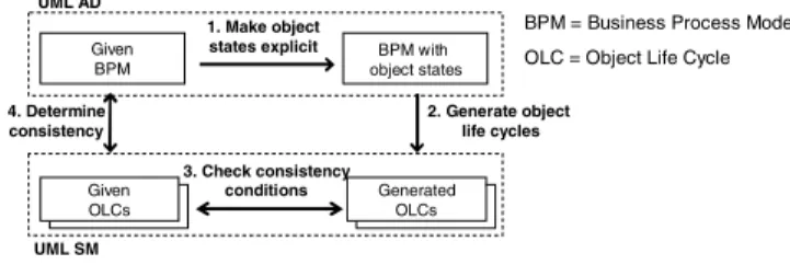
An overview of our proposed solution is shown in Figure 3. In Step 1, we make the overlap between a business process model and object life cycles explicit by adding object state information to the process model using theinStateattribute of object pins (as in Figure 1). Next in Step 2, we generate a life cycle for each
Given BPM BPM with object states Given OLCs Generated OLCs 3. Check consistency conditions 2. Generate object life cycles UML AD UML SM 1. Make object states explicit 4. Determine consistency
BPM = Business Process Model OLC = Object Life Cycle
Fig. 3.Solution overview
object type used in the process. This generation step takes us to the UML SM as the semantic domain, where we can then define and check consistency between the generated life cycles and the given ones (Step 3), which in turn allows us to determine the consistency between the business process model and the given life cycles (Step 4). The next two sections describe the generation of life cycles from a process model and the proposed consistency notions, respectively.
3
Generation of Object Life Cycles
An object life cycle generated from a given business process model for a particular object type should capture all possible state changes that can occur for objects of this type in the given process. Initial and final states also need to be identified for each generated life cycle.
Given a business process modelP where each object pin is associated with a non-empty set of states, we generate an object life cycle for each object type used inP. For an object typeo, we first create an object life cycleOLCoP that
contains only the initial state. Then, for each unique state associated with object pins of typeo, a state is added toOLCoP. Transitions and final states are added
toOLCoP according to the generation rules shown in Figure 4.
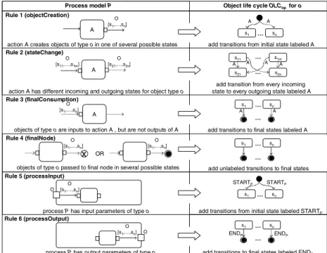
Each row in Figure 4 represents a high-level generation rule, where the left-hand side shows patterns that are matched in the process modelP and the right-hand side shows what is created in the generated object life cycle OLCoP.
Consider for exampleRule 2 (stateChange), which is applicable when some actionAhas input and output object pins of typeo. When states of the output object pin are not the same as those of the input object pin, we deduce that actionAchanges the state of objects of typeo. InOLCoP, a transition from each
incoming state to each possible outgoing state for objects of typeois added, for all cases where the outgoing state is different from the incoming state. These transitions are labeledA to indicate that they are triggered during the execu-tion of this acexecu-tion. InRules 5and6, the generated transitions are given special labels (STARTP and ENDP) to indicate that these transitions are triggered as the process begins and ends execution, respectively. The rules ensure that the generated object life cycles are well-formed, provided that all object pins in the given process model are associated with non-empty state sets. All the generation rules are explained in detail in a longer version of this paper [13].
A
action A creates objects of type o in one of several possible states add transitions from initial state labeled A
A
O [s11,…,s1m]
s11 s1m
s21 s2n
action A has different incoming and outgoing states for object type o
A A A A
Rule 1 (objectCreation)
Rule 2 (stateChange)
Process model P Object life cycle OLCoPfor o
objects of type o passed to final node in several possible states
Rule 4 (finalNode)
add unlabeled transitions to final states
s1
add transition from every incoming state to every outgoing state labeled A
process P has output parameters of type o
Rule 6 (processOutput)
add transitions to final states labeled ENDP O [s1,…,sn] s1 … sn A A O [s21,…,s2n] … … O [s1,…,sn] sn … x s1 … sn … … ENDP O [s1,…,sn] O END P
process P has input parameters of type o
s1 O
[s1,…,sn]
add transitions from initial state labeled STARTP
Rule 5 (processInput) sn … O STARTP STARTP O [s1,…,sn] OR Rule 3 (finalConsumption) A
objects of type o are inputs to action A , but are not outputs of A add transitions to final states labeled A
O [s1,…,sn]
s1 … sn
A A
…
Fig. 4.Rules for object life cycle generation
Figure 5 shows life cycles forClaim andSettlement object types (right-hand sides of (a) and (b), respectively) generated from the Claims handling process model in Figure 1 according to the generation rules presented in this section.
In the next section we show how generated object life cycles are used for defining consistency conditions to establish whether a given process model is consistent with a given life cycle for a particular object type.
4
Consistency of Object Life Cycles
We identify two consistency notions for a given business process model and an object life cycle:life cycle compliance andcoverage. A given process model is compliant with a given life cycle for a particular object type, if the process initiates only those state transitions for objects of this type that are defined in the given life cycle. Compliance allows objects of the given type to traverse only a part of their given life cycle in the process. On the other hand,coveragerequires that objects traverse the entire given life cycle in the process, but additional transitions not defined in the given life cycle may also be incurred in the process. Depending on the circumstances, one or both of these consistency notions may be required to hold. For example, if theClaims handling process (Figure 1) is used for execution and theClaim life cycle (Figure 2 (a)) is referenced by em-ployees for interpreting the state ofClaimobjects, both compliance and coverage
must hold. If the process is not compliant with the life cycle and takesClaim
objects into states not shown in the life cycle or performs different transitions, this will disconcert the employees. On the other hand, customers will be incor-rectly informed and thus unsatisfied if the process does not provide a coverage of the life cycle. An example of this occurs if a customer expects aClaim in state
Granted to eventually reach stateSettled according to the given life cycle, but this never happens in theClaims handling process.
We next give more precise definitions of compliance and coverage, providing consistency conditions that must hold between a life cycle generated from a process model for a particular object type and a given life cycle for that type. We first give two definitions that simplify the expression of consistency conditions that follow. Definitions 2 and 3 can be applied to any two object life cycles: OLCo= (S, sα, SΩ, L, T) andOLCo = (S, sα, SΩ , L, T).
Definition 2 (State correspondence).Astate correspondenceexists between a states∈Sand a states ∈S, if and only if one of the following holds:s=s,
s=sαand s=sα, ors∈SΩ ands∈SΩ .
Definition 3 (Transition correspondence). A transition correspondence
exists between a transition t = (s1, s2)∈ T and a transition t = (s3, s4)∈T
if and only if there are state correspondences betweens1 ands3, and betweens2
ands4.
In Definition 2, we define astate correspondence between two states in different object life cycles if the states are equal (i.e. have the same name), if they are both initial states or they are both final states. In Definition 3, we define a tran-sition correspondence between two transitions if there are state correspondences between their sources states and between their target states.
In Definitions 4 and 5,P is a given process model,OLCo= (S, sα, SΩ, L, T) is a given life cycle for object typeoandOLCoP = (SP, sαP, SΩP, LP, TP) is the
life cycle generated fromP foro.
Definition 4 (Life cycle compliance). A business process model P is com-pliantwith an object life cycle OLCo if and only if for each transitiontP ∈TP
that is not labeled STARTP or ENDP, there exists a transition t∈T such that
there is a correspondence betweentP andt.
According to Definition 4, life cycle compliance requires that each transition in the generated object life cycle has a transition correspondence to some transition in the given life cycle. However, there are two exceptions to this consistency condition: transitions labeled STARTP and ENDP in the generated object life cycle. These transitions are generated when the given process modelP has input or output parameters of object type o. We do not place restrictions on these transitions, thus allowing objects of typeo to be received by and passed from the given process in any state and not necessarily a state following the initial state or preceding a final state.
Definition 5 (Life cycle coverage). A business process model P provides a coverageof an object life cycle OLCo if and only if all of the following
con-ditions hold between OLCo and OLCoP: (a) For each transition t ∈ T there
exists a transitiontP ∈TP such that there is a correspondence betweentandtP,
(b) There are no transitions labeled STARTP or ENDP inTP.
Condition (a) in Definition 5 requires every transition in the given object life cycle to have a transition correspondence to some transition in the generated life cycle. Furthermore, condition (b) requires that the given process does not have input or output parameters of the given type, hence objects of this type must be created and reach their final states within the process boundaries.
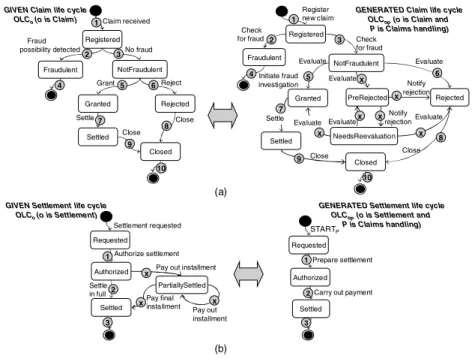
We next illustrate the notions of life cycle compliance and coverage using ex-amples. Figure 5 shows the given object life cycles for theClaimandSettlement
object types on the left and the object life cycles generated from theClaims han-dlingprocess on the right. Transitions that have a correspondence between them are marked with the same number, while transitions without a correspondence are marked with a cross.
Registered Fraudulent NotFraudulent Granted Rejected Settled Closed Claim received No fraud Fraud possibility detected Reject Grant Settle Close Close Registered Fraudulent NotFraudulent Granted PreRejected Settled Closed Check for fraud Check for fraud Evaluate Evaluate Settle Close NeedsReevaluation Rejected Notify rejection Notify rejection Evaluate Close Register new claim Initiate fraud investigation Evaluate Evaluate 1 1 2 2 3 3 4 4 5 5 6 6 7 7 8 8 9 9 Evaluate Authorized Settled Carry out payment Prepare settlement Requested STARTP Authorized Settled PartiallySettled Authorize settlement Settle in full
Pay out installment
Pay out installment Pay final installment Requested Settlement requested 1 1 2 2 3 3
GIVEN Claim life cycle OLCo (o is Claim)
GENERATED Claim life cycle OLCoP(o is Claim and
P is Claims handling) (a) (b) x x x x x x x x x 10 10
GIVEN Settlement life cycle OLCo (o is Settlement)
GENERATED Settlement life cycle OLCoP(o is Settlement and
P is Claims handling)
Fig. 5.Consistency ofClaim andSettlement object life cycles
The Claim life cycles in Figure 5 (a) satisfy all the consistency conditions
for life cycle coverage. Condition (a) from Definition 5 is satisfied since all the transitions in the given Claim life cycle have a correspondence to transitions in the generatedClaim life cycle, and condition (b) is satisfied since the
Therefore, theClaims handling process provides a coverage of the givenClaim
life cycle. However, theClaims handling process is not compliant with this life cycle, due to transitions in the generated life cycle without transition correspon-dences to transitions in the given life cycle. Figure 5 (b) shows that theClaims handling process is compliant with the givenSettlement life cycle, but does not provide a coverage for it.
5
Related Work
A related research area isobject life cycle inheritance, where consistent special-ization of behavior is required (see e.g. [5,11,14]). Currently, our main goal is to establish a link between business process models and object life cycles, and life cycle inheritance is not in focus. However, sometimes it may be required that the relation between a given process model and an object life cycle is a certain type of specialization. Thus, it would be beneficial for our approach to make use of the consistency notions already defined for life cycle inheritance.
Another related area is synthesis of state machines from scenarios [18,16], where scenario specifications are used to generate state machines for the ob-jects that participate in these scenarios. There are several significant differences between process models and scenarios however, e.g. process models do not gen-erally describe alternative scenarios and show the flow of objects between tasks rather than interaction between objects via messages modeled in scenarios. In state machine synthesis, it is possible that a synthesized state machine contains so-calledimplied scenarios [15,12], i.e. behaviors that are not valid with respect to the original scenario specifications. A similar phenomenon can occur in our life cycle generation step, which we plan to investigate further as future work.
Our consistency notions are related to the concepts of equivalence and re-finement of formal process specifications [7]. However, as discussed in [17], it is challenging to apply the existing definitions to languages such as UML AD and SM, as they do not have an agreed formal semantics. As future work we intend to establish a relation of our consistency notions to the existing equivalence and refinement definitions and investigate which are most appropriate in practice.
6
Conclusion and Future Work
Consistency of business process models and object life cycles needs to be en-sured in situations where process models manipulate business objects with an explicitly modeled life cycle. In this paper we have presented our approach to establishing this consistency. Our main contributions include a precise definition of two consistency notions, namely life cycle compliance and coverage, and a supporting technique for the generation of object life cycles from process models that enables consistency checking. With regards to tool support, we have devel-oped a prototype as an extension to the IBM WebSphere Business Modeler [1] that allows us to capture object states in business process models, generate life cycles from process models and check the consistency conditions.
As future work, we intend to validate the proposed approach using a larger case study. We also plan to extend the approach to enable compliance and cov-erage checking forseveral process models that use objects of the same type and a life cycle for this type. Further future work includes an investigation of im-plied scenarios in the context of our life cycle generation and establishing a clear relation between our proposed consistency notions and the existing equivalence and refinement definitions.
References
1. IBM WebSphere Business Modeler. http://www-306.ibm.com/software/integra
tion/wbimodeler/.
2. ACORD Life & Annuity Standard. ACORD Global Insurance Standards, Final Version 2.13.00, September 2005.
3. UML2.0 Superstructure, formal/05-07-04. OMG Document, 2005.
4. IBM Industry Models for Financial Services, The Information Framework (IFW) Process Models. IBM General Information Manual, 2006.
5. J. Ebert and G. Engels. Specialization of Object Life Cycle Definitions. Fach-berichte Informatik 19/95, University of Koblenz-Landau, 1997.
6. G. Engels, J. M. K¨uster, L. Groenewegen, and R. Heckel. A Methodology for
Specifying and Analyzing Consistency of Object-Oriented Behavioral Models. In
Proceedings of the 8th European Software Engineering Conference - ESEC’01, pages
186–195. ACM Press, 2001.
7. A.-W. Fayez. Comparative Analysis of the Notions of Equivalence for Process
Spec-ifications. InProceedings of the 3rd IEEE Symposium on Computers &
Communica-tions - ISCC’98, page 711, Washington, DC, USA, 1998. IEEE Computer Society.
8. J. M. K¨uster. Consistency Management of Object-Oriented Behavioral Models.
PhD thesis, University of Paderborn, March 2004.
9. J. M. K¨uster and J. Stehr. Towards Explicit Behavioral Consistency Concepts in
the UML. In Proceedings of the 2nd International Workshop on Scenarios and
State Machines: Models, Algorithms and Tools - ICSE’03, 2003.
10. B. Litvak, S. Tyszberowicz, and A. Yehudai. Behavioral Consistency Validation of
UML Diagrams.1st International Conference on Software Engineering and Formal
Methods - SEFM’03, page 118, 2003.
11. M. Schrefl and M. Stumptner. Behavior-Consistent Specialization of Object Life
Cy-cles. ACM Transactions on Software Engineering and Methodology, 11(1):92–148,
2002.
12. H. Muccini. An Approach for Detecting Implied Scenarios. In Proceedings of
the Workshop on Scenarios and State Machines: Models, Algorithms, and Tools -ICSE’02, 2002.
13. K. Ryndina, J. M. K¨uster, and H. Gall. Consistency of Business Process Models
and Object Life Cycles. InProceedings of the 1st Workshop on Quality in
Model-ing co-located with MoDELS 2006, Technical report 0627, Technische Universiteit
Eindhoven, 2006.
14. M. Stumptner and M. Schrefl. Behavior Consistent Inheritance in UML. In
Pro-ceedings of Conceptual Modeling - ER 2000, volume 1920 ofLNCS, pages 527–542.
Springer-Verlag, 2000.
15. S. Uchitel, J. Kramer, and J. Magee. Detecting Implied Scenarios in Message
Sequence Chart Specifications. InProceedings of European Software Engineering
16. S. Uchitel, J. Kramer, and J. Magee. Synthesis of Behavioral Models from
Scenar-ios. IEEE Transactions on Software Engineering, 29(2):99–115, 2003.
17. M. von der Beeck. Behaviour Specifications: Equivalence and Refinement Notions.
InVisuelle Verhaltensmodellierung verteilter und nebenl¨aufiger Software-Systeme,
8. Workshop des Arbeitskreises GROOM der GI Fachgruppe 2.1.9 Objektorientierte Software-Entwicklung, Universit¨at M¨unster, 2000. Technical report 24/00-I.
18. J. Whittle and J. Schumann. Generating Statechart Designs from Scenarios.
In Proceedings of the 22nd International Conference on Software Engineering