Covenant Journal of Informatics & Communication Technology. Vol. 5 No. 1, June, 2017
An Open Access Journal Available Online
Design and Implementation of a Low-Cost Low
Interaction IDS/IPS System Using Virtual Honeypot
Approach
Olamilekan Shobayo
1,2& Marcos Rodrigues
11
Sheffield Hallam University, Sheffield, United Kingdom
2
Covenant University, Ota, Nigeria Contact(s). [email protected], [email protected],
Abstract— Network attacks have become prominent in the modern-day web activities and the black hat community have also gain more sophistication with the tools used to penetrate poorly guarded or unguarded networks. Network security administrators have also moved swiftly to counter the threats posed by the attacker with different network intrusion detection and monitoring tools. Low interaction honeypots were developed to entice hackers without causing any serious downtime to the production network, so that their activities and the way they access the network can be studied with a minimal setup cost. In this work, a low interaction virtual honeypot using the Honeyd daemon to lure attackers to the network and alert the attacker's activities in the network using the Snort IDS. The data captured is analysed based on the protocol and port used. It is then validated by analysing the attacker's activities once it is logged and accessed through Wireshark protocol analyser.
Keywords/Index Terms—Low Interaction Honeypot, High Interaction Honeypot, Intrusion Detection and Prevention, Traffic monitoring
1. Introduction
According to the survey carried out by (Richardson, 2010), Cyber-attacks have become a pertinent issue that have cost organisations worldwide an estimated $150 million stating that much of attack targeted to organisations ranks from Malware infection 67%, Fraudulently represented as a sender of phishing mail 37%, laptop or mobile hardware theft or loss 34% and Denial of service 17%.
During the past decade, there has been
numerous network security tools
developed for organisations which includes Firewalls and NIDS. Firewall for example, helps protect these organisations by preventing an attacker from gaining access to the internal network and tools such as NIDS allows organisations to detect and identify attacks, provide mechanisms that react to the detected attacks or at the barest 48
Marcos Rodrigues& Olamilekan Shobayo CJICT (2017) 5(1) 48-64
minimum, reduces the effect of the attack. But because attackers always come with new tricks and these tools lacks the functionality of detecting or fending off the newer attacks and the collection of more information about the attacker's activities, skills and methods. For example, Signature based IDS's does not contain the attack signature of a newer attack in its signature database, therefore it will allow an attack to get through to the network if its signature is different from the one contained its database.
Nowadays, for organisations to protect their networks and build efficient security systems, it is necessary for network security system developers to gain the attackers knowledge and attack plots (Anuar, et al., 2006). Many non-profit organisations and educational institutions have spent time to research into cyber-attacks and analyse the methods and tactics used by the so-called Black hat community which act
against organisations production
network.
An important network tool that is used by different organisation to monitor the Black hat community is the Honeypot. According to (Provos & Holz, 2008), a honeypot is a closely monitored computing resource that we want to be probed, attacked or compromised. It is a form a decoy system that is set up to detect or confuse unauthorised attempts on information systems. Honeypots also allows us to analyse how attackers
explore system and network
vulnerabilities. Because honeypots have no production values it constitutes an extra cost when it is being set up in a production network because of the extra network components that is required for
the setup. As suggested by (Ayeni, Alese and Omotosho 2013) Intrusion detection has become a very delicate matter over the last few years within the broad realm of network security. With so much advancement in hacking, if attackers try hard enough, they will eventually succeed in infiltrating the system. Therefore, there is a need to constantly or periodically monitor what is taking place on a system and look for suspicious behaviour. Vulnerabilities in common security components such as
firewalls, security patches, access
control and encryption are inevitable, so
hackers take advantage of these
shortcomings to infiltrate the system. (Sabah & Vandana, 2013) To reduce cost, low interaction honeypots were developed which will simulate the
network components instead of
incurring the cost of setting up the high interaction counterpart with lesser sophistication and richness of data as the alternative forgone. This report focuses on the low interaction technique for honeypot deployment.
2. Background and related work
Network attacks as defined by
(Ghorbani, et al., 2010) ―is a set of malicious activities to disrupt, deny, degrade or destroy information and service resident in computer networks‖. Streaming of data through a network is the main source of attack on that network and its aim is to disrupt the traffic going through that network and making the network vulnerable to other attacks by reducing its integrity and confidentiality. Network attacks ranges
from an individual receiving an
obnoxious email from another
individual to attack on the components of a network, important information and
Marcos Rodrigues& Olamilekan Shobayo CJICT (2017) 5(1) 48-64
critical data. Examples of attacks on
computers include email viruses,
worms, Trojan horses, unauthorised access, amending data on a system by taking advantage of a bug on the software. To perpetrate these attacks, the methods used by the attackers can be generalised into Masquerading, Social Engineering, Vulnerability Scanning and functionality abuse.
Social Engineering attack is used to mislead its prey by persuading them aggressively to give their authentication
details (Amitabh, et al., 2004).
Examples are email phishing and Trojan Horse; Masquerading attack is when the attacker poses as a legitimate user in a network to gain higher privileges than they should i.e. logging in as an administrator into a network which they are not. This is achieved by bypassing the means of authentication with stolen logon passwords and user identities; Vulnerability scanning methods are software bugs attached to a legitimate program which the attacker uses to obtain access illegally to a system. Examples include improper handling of temporary files, race conditions and buffer overflows.
In order to manage honeypot system using web interface, (Anuar, et al., 2006) created Honeyd@WEB. Through web interface, Honeyd@WEB was used to design a low-involvement (low-interaction), production, dynamic and manageable honeypot. It combines techniques such as "Deception ports" on
production network to simulate
honeypot services which are used in place of well-known services such as HTTP, POP, DNS and FTP and "proximity Decoys" where honeypots decoys are situated very close to the
production host i.e. in the same local subnet. The main purpose of their research was to detect real systems and
the Honeyd@WEB solution was
deployed in the internal network to detect internal attackers.
Similarly, they also used the
Honeyd@WEB to detect firewalls that are not configured properly and to detect worms and Trojans.
(Vollmer and Manic 2014), created a deceptive virtual host (low interaction honeypot) by combining 3 components namely:
- Network Entity Identification (NEI).
- Dynamic Virtual Host (DVH)
configuration.
- Virtual Host Instantiation (VHI).
The NEI component is used to monitor the network traffic by extracting the source, destination and activities of each port. They evaluated tools like P0f, Ettercap, Snort, TCPdump and Ntop to provide network host identification. The DVH component is configured using Honeyd as it provides autonomous configuration with low expenses as
compared to the manual (High
interaction honeypot) configuration. Its main objective is to automatically configure and update a random amount of virtual host dynamically based on the data it gathered from the actual host using Ettercap. The DVH components was described in 4 sections namely OS selection, OS name mapping, MAC creation and Network service emulation. The VHI and update component is used to instantiate the virtual host. They created an initial configuration file and made changes to the configuration file of the virtual host running under Honeyd while the system is running.
Marcos Rodrigues& Olamilekan Shobayo CJICT (2017) 5(1) 48-64
(Kaur and Saini 2013), created a Honeynet to analyse network traffic and prevent attacks on protocol and port basis. The Honeynet was deployed to capture keystrokes of the attacker's activities and the captured data was analysed for the purpose research. Honeyd was used as the low interaction honeypot to create virtual host and
simulate some services on them
including TCP, UDP and ICMP. For the high interaction honeypot, a real host running on Windows XP SP2 operating system was used and Sebek-win-3.0.5 was also used as the data capture tool. A Honeywall is also configured in the setup with all three NIC's attached to the Honeywall system used at once. The Honeywall connected the Honeynet (Low and High interaction honeypot) and the production network in a bridge mode. This bridge mode made it very difficult for the attacker to detect the honeypot.
The Honeywall was configured not to have any IP address except for the interface connected to the management machine. This feature enables the Honeywall to appear in a stealth mode and transparently control and detect all information that moves across it. When malicious activities are detected, it is forwarded to the Honeynet machines i.e.
(the Low and High interactions
honeypots) and the activities are logged and the data captured are analysed. HPing3 was used to launch attacks on
the honeypots from a computer
connected to the production network, the attacks launched includes: SYN flag, DoS, Smurf attack and flooding by using IP spoofing. The honeypots could capture the launched attacks and the
types of attacks were shown using the Sebek software.
3. System Architecture
The architectural model of the
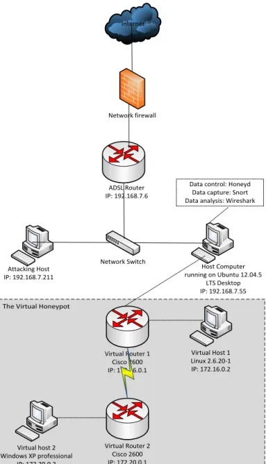
implemented virtual honeypot network is shown in Figure 1 and it is achieved using the Honeyd software to simulate the virtual hosts that can be interactive with an attacker and used to provide arbitrary services like TCP, UDP and ICMP to deceive the attacker into thinking that it is communicating with a real computer on a real network.
Although the Honeyd software can also be configured to log the activities of the attacker, the Snort IDS/IPS software was used for the logging of these activities because it provides a more
powerful analysis and signature
categorisation of the attacker's activities. Both software provides both logging and analysis characteristics and to make this work more robust, the Wireshark network protocol analyser was selected to give detail analysis of the attacker’s activities on the network by monitoring the inflow and outflow of data across the host computer on the interface connected to the internet which is also configured as the same port where the honeypot and the IDS/IPS in listening to.
The system architecture in Figure 1 shows the experimental design of the proposed technique for the deployment of the IDS/IPS system. As seen from the diagram, the IDS system is placed behind a firewall. The firewall helps filters traffic between a protected (internal) network and an unprotected (external) network. This also helps to make the attacker thinks he is attacking a real network.
Marcos Rodrigues& Olamilekan Shobayo CJICT (2017) 5(1) 48-64
It also keeps unwanted packets from
entering the protected network.
Honeypots can either be placed in the front of a firewall, in the DMZ, or behind a firewall. When dealing with IDS/IPS networks, as suggested by (Annamma , et al., 2011) it is always a good practice to setup the honeypots behind the firewall to appear as a legitimate network to the intruder. Therefore, for this design, I have chosen to implement the Honeypot behind the firewall to be in accordance to industry
standard and to preserve the
authentication of the Honeypot concept.
3.1. Virtual Honeypot Implementation
The virtual host is used to simulate network delay and packet loss rate. The simulated network consists two virtual host and two Cisco routers. The virtual
router 1running as Cisco 2600 series personality is used to separate the network 192.168.7.0/24 and the network 172.16.0.0/24. Virtual router 2 also running on the cisco 2600 personality is
used to separate the network
172.16.0.0/24 and the network
172.20.0.0/24. Virtual router 1 access address is 172.16.0.1 and the virtual router 2 access address is 172.20.0.1. The virtual host 1 in the 172.16.0.0/24
network with the IP address
172.16.0.2/24, running on the Linux 2.6.20-1 as the personality, while the virtual host 2 is on the network 172.20.0.0/24 network with the IP address 172.20.0.2/24 and running Windows XP professional as its personality.
Marcos Rodrigues& Olamilekan Shobayo CJICT (2017) 5(1) 48-64
FIGURE 1. IMPLEMENTED SYSTEM ARCHITECTURAL DESIGN
The Virtual Honeypot
Internet Virtual Host 1 Linux 2.6.20-1 IP: 172.16.0.2 Network Switch Network firewall Virtual Router 2 Cisco 2600 IP: 172.20.0.1 Virtual Router 1 Cisco 2600 IP: 172.16.0.1 Virtual host 2 Windows XP professional IP: 172.20.0.2 ADSL Router IP: 192.168.7.6 Attacking Host IP: 192.168.7.211 Host Computer running on Ubuntu 12.04.5 LTS Desktop IP: 192.168.7.55 Data control: Honeyd
Data capture: Snort Data analysis: Wireshark
3.2Configuring the Honeyd
When configuring the Honeyd software to set up the virtual honeypot, it must be ensured that IP forwarding is disabled on the host computer that houses the Honeyd (Provos & Holz, 2008).If IP forwarding is enabled, then IP packets which the Honeyd receives for the virtual honeypots are forwarded to another computer in the 192.168.7.0 network where the host computer is
located. In order to disable IP
forwarding, the command below was issued on the host computer:
echo 0 > /proc/sys/net/ipv4/ip_forward Before running Honeyd, it was ensured that the host computer can answer to all ARP requests which are sent by the router for the IPs of the virtual honeypots. This is achieved using the farpd tool for spoofing the ARP requests (Provos, 2008). It listens on the host network interface, i.e. the 192.168.7.0 network interface and responds with the MAC address of the Honeyd for the
received ARP requests on the
corresponding IP addresses. The
incoming packets can be received through the Honeyd network interface with the help of the farpd. It allows for easy monitoring and capturing traffics
which are sent to the virtual honeypots. This is achieved by running the
following command on the host
computer:
farpd <IP address of virtual honeypot]> -i eth0
where eth0 is the physical network interface of the host computer. shell), TCP port 20 (FTP), TCP port 88 (Kerberos authentication system) and UDP port 161 (SNMP). These ports are set to open for the attacker to establish connections to the virtual honeypot network only and it's not made to run any scripts or log any activities as these activities are implemented with the snort IDS system. The drop action is used to drop the entire packet to the port by default. Honeyd runs as a background process and as a user nobody which provides the security embedded within the Honeyd framework. In order to run the Honeyd configuration from the
honeyd.conf file, the following
command was issued on the host computer
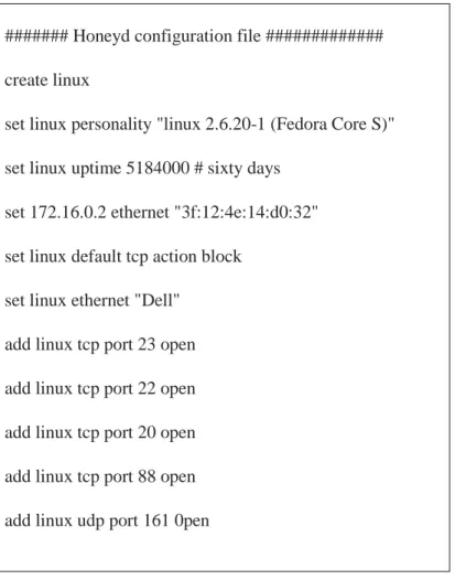
Some part of the main commands used in the Honeyd configuration file to set up the virtual honeypot network is shown in table 1:
Marcos Rodrigues& Olamilekan Shobayo CJICT (2017) 5(1) 48-64
TABLEI. HONEYD CONFIGURATION COMMAND
The create command creates a template whose personality is 'linux' and it binds the honeypot's IP address to the personality. The set and add commands is used to change the configuration of the personality. The set command helps to assign the personality "linux 2,6.20-1 (Fedora Core S)" from the Nmap fingerprinting file. The uptime of the host shows how long the system has been running. The uptime was spoofed to be equal to 60 days i.e. 5184000 seconds to give enough room from the time of writing the configuration of the virtual honeypot to the time when the attack will be simulated. The add command opens the ports on the
virtual honeypot, and specifies which services should run on each port. For the attacker to feel that it is attacking a real system on a real network, the open action is used to open most of the well-known ports such as the TCP port 23 (telnet), TCP port 22 (secure:
# honeyd -d -i eth0 172.16.0.0/16 172.20.0.0/16 -f/etc/honeypot/honeyd.conf At this point, Honeyd start listening on eth0 interface and answering to the packets for the network address 172.16.0.0/16 and 172.20.0.0/16 respectively of the configured virtual honeypots.
####### Honeyd configuration file #############
create linux
set linux personality "linux 2.6.20-1 (Fedora Core S)"
set linux uptime 5184000 # sixty days
set 172.16.0.2 ethernet "3f:12:4e:14:d0:32"
set linux default tcp action block
set linux ethernet "Dell"
add linux tcp port 23 open
add linux tcp port 22 open
add linux tcp port 20 open
add linux tcp port 88 open
add linux udp port 161 0pen
Marcos Rodrigues& Olamilekan Shobayo CJICT (2017) 5(1) 48-64
Ping, Nmap, telnet and traceroute tools was used to test that the Honeyd installation is working as configured and also to see if it is correctly receiving network traffic.
3.3 Configuring the Snort IDS
According to (Roesch, et al., 2015), Mostly all network cards have features named "Large Receive Offload" (lro) and "Generic Receive Offload" (gro). With these features enabled, the network card performs packet reassembly before they become processed by the kernel. Therefore, it is recommended to turn off both the LRO and GRO because Snort will truncate packets larger than the default snaplen of 1518 bytes. To disable
LRO and GRO the following command was run on the host computer:
sudo apt-get install -y ethool sudo ethool -K eth0 gro off sudo ethool -K eth0 lro off
After snort was installed, some files and directories which are required by snort were created and permissions were set on the files. Snort keeps all configurations and rule files in etc/snort, and all alerts generated by Snort will be logged to /var/log/snort. This is achieved running the following commands on the host network
sudo groupadd snort
sudo useradd snort -r -s /sbin/nologin -c SNORT_IDS -g snort sudo mkdir /etc/snort
sudo mkdir /etc/snort/rules
sudo mkdir /etc/snort/preproc_rules
sudo touch /etc/snort/rules/white_list.rules /etc/snort/rules/black_list.rules /etc/snort/rules/local.rule
sudo mkdir /var/log/snort
sudo mkdir /usr/local/lib/snort_dynamicrule sudo chmod -R 5775 /etc/snort
sudo chmod -R 5775 /var/log/snort
sudo chmod -R 5775 /usr/local/lib/snort_dyamicrules sudo chown -R snort:snort /etc/snort
sudo chown -R snort:snort /var/log/snort
sudo chown -R snort:snort /usr/local/lib/snort_dynamicrules
In order to write the configuration for
snort to capture the ongoing
communications with the different protocols configured on the Honeyd, the
Snort configurations file at
etc/snort/snort.conf. When snort is run with this file as an argument, it tells snort to run in NIDS mode.
Before Snort is ran, some edits were made to the default configuration file by commenting out of individual rule files that are referenced in the snort configuration file. The following line of command was used to out all the ruleset in the snort.conf file
sudo sed -i 's/include \$RULE_PATH/#include \$RULE\_PATH/ ' /etc/snort/snort.conf
Marcos Rodrigues& Olamilekan Shobayo CJICT (2017) 5(1) 48-64
In order to change the configuration file, Gedit text editor was installed and the following command was used to edit the snort.conf file
sudo gedit /etc/snort/snort.conf
Because the attack sequence to be alerted by the Snort software were to be simulated, the Snort rules to capture the costumed attack signatures as written in the local.rule configuration file. The
local.rule file was enabled by
uncommenting the #include
$RULE_PATH/local.rule. Once the
configuration file is ready, Snort will verify that the file is valid and all the necessary files that it references were correct.
Currently, Snort does not have any loaded rules i.e., the rule files referenced in snort.conf is empty. The Snort rule
was written into the
etc//snort/rules/local.rule. By
uncommenting the #include
$RULE_PATH/local.rule on the Snort configuration file, Snort was instructed that the local.rule files should be loaded. When Snort loads the file on start up, it will see the rule that was created and the rule will be implemented on all traffic incoming and outgoing on the eth0 interface.
To alert every ICMP packets that is moving through the eth0 interface, the following command was written into the
etc/snort/rules/local.rule file alert ICMP any any -> $HOME_NET any (msg:"ICMP alert" ; sid :10000001; rev:001;) The diagram in Figure 2 shows the captured message on the Snort console.
FIGURE 3. SHOWING THE RULE PORT COUNT
As seen from the Figure 2 above, the Snort IDS have could detect rules for any ICMP, UDP and TCP packets that is
destined for the host computer through the eth0 interface. Snort was then started in the NIDS mode, and was told to
Marcos Rodrigues& Olamilekan Shobayo CJICT (2017) 5(1) 48-64
output any alert directly to the console. Snort was run from the command line
using the following flags :
-A console The 'console' option prints fast mode alert to stdout
-q Quiet mode. Don’t show banner and status report
-u snort Run Snort as the following user after startup
-g snort Run Snort as the following group after startup
-c /etc/snort/snort.conf The path to the snort.conf file
-i eth0 The interface to listen to
The command issued according to the flag listed above is shown thus: sudo /usr/local/bin/snort -A console -q -u snort
-g snort -c /etc.snort/snort.conf -i eth0
3.4Configuring the Wireshark
The host system is configured with a DEB-based distribution, i.e. the Ubuntu 12.04.4 LTS operating system, Wireshark was installed from system repositories through the terminal window and the following commands were used:
Sudo apt-get install wireshark
4. Validation of Result
In this section, some validation test was carried out to verify the workability of the implemented system by carrying out different attack simulation on the system setup.
Hping3 (Sanfilippo, 2010) was used to launch simulated attack on the virtual honeypot setup to test the functionality of the system. The simulation does not actually project a hacking scenario, it proves to be effective in checking how the virtual honeypot works, how the Snort IDS logs the simulated attack sequence and how the data is captured using the Wireshark network protocol analyzer. The hping3 was installed in the attacking host shown in the diagram in Figure 1. Attacks to simulate the
launching TCP, UDP and ICMP packets are being directed to the honeypot setup. The command that is used to carry out the attack sequence is the hping3 command. It requires administrative privileges to run it from the attacking host machine. The attacking host machine is presumed to be located on the production network i.e. it simulates that an attacker has hacked into the production network and has gained access to the network facilities with the rights to communicate with every computer on the production network including the virtual honeypots setup with the aim of bringing down the network and causing downtime.
A general hping3 command that can be used to send attacking packets to a host is shown below
#hping3 <victim IP> -V –c 1000000 –d 512 –S –w 32 –flood –rand-source
Also, to spoof the source IP address, the –a command option can be used. When the spoofing option is used, the source IP of the attacker is concealed, albeit the honeypot system still detects the attack. The command option used by hping3 is shown below.
4.1 Scenario 1: Use of TCP SYN Flag to Flood the Host Machine
The command used to create a TCP SYN flag flood on the attacker’s machine is shown below
#hping3 <Victim’s IP> -V -c 10000 –d 512 –S –w 32 --flood Immediately the command is run from
the attacking host, connection is setup with the honeypot and data is being received through the TCP protocol. To receive TCP connection with the host computer, it uses the SYN flag and an acknowledgement is received for the connection. As soon as a connection is established, the command allows TCP packets to flood the host (victim’s)
computer. These activities are captured and logged against the Snort IDS rule and the result
is output to its console. The Wireshark application is also started to listen on the
eth0 interface where the virtual
honeypot (Honeyd) and the Snort IDS is also configured. The figure 3 below shows the data that was logged and captured
.
FIGURE 3. SNORT ALERT OF THE TCP FLOOD
V Verbose-mode c Packet-count d Data-size S SYN flag w Window-size 59
Data from Figure 3 show that TCP packets are being sent from a source IP address of 192.168.7.211 which shows that the attacker is on the same subnet as
the honeypot system. Once the
command to run the Snort IDS is started, the TCP packed flood begins to be logged on the console. The first line from the figure shows how both host
negotiates connections with every
packet sent and every alert logged. An acknowledgment is also received at the
reverse end of the communication. The host system established the connection using a dynamically assigned port number which it held for the length of the communication, while the assigned outgoing TCP port of the attacking host increases with a value of 1 for the next establishment of connection. The log
also shows the output message
configured on the local.rule file of the Snort IDS, showing both the sequence number and the priority level of the rule.
FIGURE 4. WIRESHARK CAPTURED TCP DATA
The Wireshark provides more insight to the TCP attack flood, when it is filtered to express TCP transactions only. The details from the frame number 37 selected above depicts a sent TCP frame from the attacker’s machine. It shows the attacking host MAC address and the type of computer from which the attack is propagated (in this case a VMware machine). This data can help to track the location of the attacker and to prosecute them. It also shows the aggregated
amount of flow, source byte, source packet, and destination flow and destination packets. The large amount of TCP flow confirms the flooded data from source to destination.
4.2 Scenario 2: Use of UDP Packets to Flood the Host Machine
The command used to launch the UDP flood attack on the honeypot system in this scenario is shown below:
#hping3 <Victim’s IP> -V -c 10000 –d 512 –S –w 32 -2 --flood
The difference from the command used to flood the TCP packets is the -2 command. It is the hping3 command hat is used to flood UDP packets. The default command without the -2 will only launch TCP packets. Since UDP
does not require a connection
establishment like the TCP, the
attacking host starts sending packets immediately the command is run. The Snort IDS alert is shown in Figure 5.
FIGURE 5. SNORT CAPTURE OF UDP FLOOD PACKETS
The Snort IDS logs an ICMP packet every time a UDP packet is sent to the honeypot system. The hping3 tool uses the ICMP to generate a form of connection with the host before flooding it with the UDP packet. The destination port is 0 but all the unassigned port numbers between 0-65535 was used by
the attacking host to flood the UDP packets.
The Wireshark capture also depicts both the ICMP and UDP packets and the highlighted UDP packet also shows the time the packet is sent in seconds, the source and destination address of the UDP packet. The Figure 6 below shows the Wireshark capture
FIGURE 6. WIRESHARK UDP FLOOD CAPTURE
4.3 Scenario 3: Use of ICMP Packets to Flood the Host Machine
The command used to launch the ICMP flood attack on the honeypot system in this scenario is shown below:
#hping3 <Victim’s IP> -V -c 10000 –d 512 –S –w 32 -1 --flood
The -1 command of the hping3 was used to generate the ICMP packet in this scenario. The Snort IDS capture is shown Figure 7.
FIGURE 7. SNORT CAPTURE OF THE ICMP FLOOD
As seen from figure 7, the rule captured the ICMP packets coming from the attacking host computer and it was
logged on the console of the Snort IDS. The source, destination and port numbers are shown as well.
Marcos Rodrigues& Olamilekan Shobayo CJICT (2017) 5(1) 48-64
5. Conclusion
In this paper, a virtual honeypot setup
that combines Intrusion Detection
System has been presented. It can capture all types data proposed to be used to attack the network which includes TCP, UDP and ICMP, and it also gives a lot of information about the attacking protocols via the Wireshark network analyzing tool. Alerts from the Snort IDS console and captures from Wireshark reveals the protocols the attacker is using.
Honeypots whether physical or virtual are meant to emulate real production networks at a level of operation, mostly deploying the protocols that attackers find interesting to obliterate. It is not of full guarantee that a network would be attacked or spoofed and most of the security defense system might just end up being redundant. This option will be sure to provide a cheaper solution for the decoy system.
References
Roesch, M., 2015. Snort. [Online]
Available at:
https://www.snort.org
Amitabh, M., Ketan, N. & Animesh, P., 2004. Intrusion Detection in
Wireless Ad Hoc Ntwork. IEEE
wirless communications, Issue 04, pp. 48-60.
Annamma , A., Runuka, P. B. & Abhas, A., 2011. Design and Efficient Deployment of Honeypot and
Dynamic Rule Based Live
Network Intrusion Collaborative
System. International Journal of
Network Security & its
Application, III(2), pp. 52-65. Anuar, N. B., Zakaria, O. & Yao, C. W.,
2006. Honeypot Through Web (Honeyd@WEB): The Emeging
of Security Application
Integration. Informing Science
and Information Technology,
III(1), pp. 47-56.
Ghorbani, A. A., Lu, W. & Tavallaee,
M., 2010. Network Intrusion
Detection and Prevention. 1st ed. Boston: Springer Verlag.
Kaur, G. & Saini, J. S., 2013.
Implementation of High
Interaction Honeypot to Analyse
The Network Traffic and
Prevention of Attacks on
Protocol/Port Basis. International
Journal of Computer Application,
LXII(16), pp. 22-29.
Provos, N., 2008. Development of the
Honeyd Virtual Honeypot.
[Online]
Available at:
http://www.honeyd.org/
Provos, N. & Holz, T., 2008. Virtual
Honeypots: From Botnet Tracking to Intrusion Detection. 1st ed. Boston: Pearson Education, Inc..
Richardson, R., 2010. 2010/2011
CSI/FBI Computer Crime and
Security Survey. [Online]
Available at:
http://gatton.uky.edu/FACULTY/ PAYNE/ACC324/CSISurvey2010 .pdf
[Accessed 12 June 2015].
Roesch, M., Green, C. & Caswell, B.,
2015. The Snort project: Snort
2.9.7.3. [Online] Available at: https://s3. Amazon ws.com/snort-
org-site/production/document_files/fil
Marcos Rodrigues& Olamilekan Shobayo CJICT (2017) 5(1) 48-64
es/000/000/086/original/snort_ma nual.pdf
Sabah, S. & Vandana, D., 2013. Roaming Honeypots Along With IDS in Mobile Ad-Hoc Networks.
International Journal of
Computer Application, LXIX(23), pp. 15-21.
Sanfilippo, S., 2010. Hping Manpage.
[Online] Available at:
http://www.hping.org
[Accessed 15 February 2017]. Vollmer, T. & Manic, M., 2014.
Cyber-Physical System Security with
Deceptive Virtual Host for
Industrial Control Networks.
IEEE Transanctions on Industrial Informatics, X(2), pp. 1337-1347.
Wang, J. & Zeng, J., 2011. Construction of large-scale Honeynet Based on
Honeyd. Procedia Engineering,
2011, Vol.15, pp.3260-3264,
XV(1), pp. 3260-3264.
Weizhe , Z., Hui , H. & Tai-hoon , K.,
2013. Xen-based Virtual
Honeypot System for Smart
Device. Springer Science and
Business Media, III(2), pp. 1-18. Zhou, Z., Chen Zhongwen, Z., Zhou
Tiecheng, Z. & Guan Xiaohui, Z., 2010,. The study on Network Intrusion Detection System of
Snort. International Conference
on Networking and Digital
Society, II(1), pp. 194-196.