USING UML TO MODEL DISTRIBUTED SYSTEM ARCHITECTURES
M. Nikolaidou12, N. Alexopoulou12, A. Tsadimas12, A. Dais2, D. Anagnostopoulos1{[email protected], [email protected], [email protected], [email protected], [email protected]}
1 Harokopio University of Athens, 2 Department of Informatics and Telecommunications,
El. Venizelou Str, 17671Athens, Greece University of Athens, Panepistimiopolis, 15771, Athens, Greece
Abstract
Distributed system configuration is a complex process, since it involves solving interrelated issues, corresponding to different configuration stages usually supported by automated or semi-automated independent tools. A common model for distributed system representation in all configuration stages enables the identification of unclear application specific dependencies between discrete stages. It should also be easily realized in various software tools used to automate discrete configuration stages and facilitate the designer to efficiently provide system specifications. We propose to use UML to model all aspects of distributed system configuration process by extending and integrating different diagram types. Alternative views of the system emphasizing specific configuration stages are offered through the realization of extended UML diagrams. Rational Rose software platform is used for implementation purposes. Keywords
Distributed System Model, UML 2.0 extension, Distributed System Configuration, XML
1. INTRODUCTION
As distributed systems become more complex, there is a constant effort to provide a common interface for all application users [20]. The J2EE architecture [1] contributes towards this direction, since it provides a common user application interface through the Web both at Intranet and Internet level. Significant vendors, such as BEA, IBM and Oracle [9], provide software development platforms, such as WebLogic [2], WebSphere [21] and Oracle Application Server [16], which support both J2EE and custom architectures and facilitate application integration. Such platforms contribute to distinguishing application logic from the user-interface and enable users to access any application through a common interface using a web client. Thus, they contribute to distributed system configurability and extendibility.
Even though, vendors actively promote information system development using the aforementioned software platforms, the proposed solutions, although expensive, often do not provide the desired performance [18]. A potential cause is that, configuration issues, although interrelated, are solved in isolation. Distributed system configuration is a complex process, since it involves solving interrelated issues, as application configuration (e.g. process/data allocation and replication), network configuration and performance evaluation, corresponding
to different configuration stages. A systematic approach for distributed system configuration is presented in [12]. In order to ensure distributed system performance, their configuration dependencies must by identified and explored. Since the underlying network topology affects application configuration, the relationship between resource allocation policy and network architecture should be easily explored, thus models used for the representation of distributed system architectures within each stage should be exchangeable. Configuration stages are supported by automated or semi-automated tools [3, 5, 10, 11, 18]. In order to provide exchangeable models, the modeling framework adopted within each stage should be realizable in various software tools. A common model representing distributed systems in all configuration stages will facilitate model exchange and ensure interoperability between software tools supporting each stage. This model must support distributed system representation in a multi-layered fashion and enable description of any kind of application, thus be extendable. It should also be easily realized in various software tools used to automate discrete configuration stages and facilitate the designer to efficiently provide system specifications.
As system designers are usually familiar with UML [15], we decided to use UML notation to model all aspects of distributed system configuration process in a multi-layered fashion by integrating different diagram types [4]. Although, UML is mainly used for software engineering (e.g. when designing and implementing application components), UML concepts may be applied in system engineering as well (e.g. when allocating application components to hardware resources and designing the system architecture). In [6, 8], UML sequence diagrams facilitate the description of client-server architectures emphasizing process triggering. However, the description of internal process functionality is not facilitated, while the dependencies between applications and network are be modeled. Thus, alternative system views must be provided facilitating their identification.
The rest of the paper is organized as follows: In section 2, we briefly discuss the proposed distributed system configuration framework. Configuration stages are identified and basic properties of the proposed
meta-model are presented. In section 3, we focus on distributed system modeling using UML. Alternative model views, corresponding UML diagrams and UML 2.0 extensions are described. Emphasis is given to application description. Conclusions reside in section 5.
2. DISTRIBUTED SYSTEM CONFIGURATION FRAMEWORK
Distributed systems are composed of distributed
applications and the underlying network. Distributed
applications are currently built based on client-server models and consist of multiple tiers [19]. The underlying network consists of heterogeneous Intranets and Internet connections usually integrated through TCP/IP protocol stack. Users have their own workstation (diskless or not), while server processes are executed on dedicated server nodes.
The proposed distributed system configuration stages and their interaction are analytically described in [12, 14].
Functional configuration (stage 1) corresponds to the
description of system specifications. Logical and physical
configuration (stages 2 and 3) deal with application
configuration (process/data allocation and replication policies) and network design respectively. As resource allocation and network configuration problems cannot be independently solved, stages (2) and (3) are repeatedly invoked until an acceptable solution is reached. System configuration phase must facilitate the performance
evaluation (stage 4) of the proposed solution prior to
implementation. If system requirements are not satisfied, logical and physical configuration are re-initiated. Stages 2 and 3 are usually automated by software tools as those described in [11, 5, 18, 3]. Stage 4 is usually performed using discrete event simulation [13, 7].
We decided to adοpt UML to represent distributed systems, since a) it is a widely accepted standard and most system designers are familiar with it, b) it allows the graphical representation of specifications and c) it facilitates the automated implementation of model extensions. Three alternative views are utilized emphasizing specific requirements of each configuration stage. Application view is used to describe functional specifications (e.g. application logic and user behavior).
Site view facilitates the definition of system access points
and the resource allocation and replication. Resources (e.g. processes and data) and the way they interact are already described through application view. Physical view
provides for network infrastructure modeling. The site and physical view correspond to application and network architecture respectively, thus they are interrelated. This interrelation must be reflected to the corresponding UML diagram entities to ensure distributed system performance. Both site and physical views are decomposed into hierarchical levels of detail. At the
lower level, network nodes are related to process/data replicas.
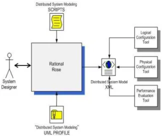
A UML profile is introduced to implement the distributed system model. This profile, called “Distributed
System Modeling”, is imported within Rational Rose
platform ([17]), which acts as the user interface for the system designer (figure 1). In order to model all aspects of distributed system configuration process, different UML diagrams are integrated and properly extended. Additional functionality needed to manipulate the model was embedded within Rose platforms (as addins). Functional configuration is strongly related to model definition. Thus, it is performed within Rose environment. Application, Site and Physical views are created within Rose by the designer as extended UML diagrams. Additional functionality is embedded within Rose, as custom scripts, to facilitate the description of specific distributed system characteristics.
Figure 1: Distributed System Representation Framework
Logical and physical configuration stages are semi-automated using heuristics by appropriate decision-support software, for example IDIS [11]. They aim at filling specific properties of site and physical view respectively. To evaluate distributed system performance, the discrete event simulation tool described in [13] can be used. The simulator uses as input the overall distributed system model, after the construction of application, site and physical view. Thus, there is a need for data exchange between Rose and the tools used to automate these stages. XML was adopted for this purpose. The model created by the designer through Rose is exported in XML in order to be used by the proper configuration tool and imported again in order for the designer to view corresponding results. Additional functionality is embedded within Rose to enable view management and invocation of external software tools.In the following, we focus on UML extensions needed to efficiently model distributed system architectures.
3. DISTRIBUTED SYSTEM MODEL USING UML In the following, we discuss alternative model views and corresponding modeling issues. UML diagrams are used to represent different aspects of the distributed system model suitable for each view. Distributed system entities are depicted as UML model elements included in the corresponding diagram, properly extended to include additional properties and support additional constraints.
The stereotype mechanism was efficient to create the
distributed system meta-model.
Physical view refers to the aggregate network. Network is a composite entity, which is repeatedly refined to represent network topology. Network nodes are either
workstations allocated to users or server stations, running
server processes. Specifically, nodes consist of one
processing, one storage and one communication element.
UML deployment diagrams are commonly used to represent network architectures [6]. In the proposed model, physical view is represented as a deployment diagram. No additional stereotypes are needed to represent network architecture, thus physical view is not further discussed. Instead, we focus on application architecture and functionality representation. The corresponding model supported during configuration stages is presented in figure 2, as a UML class diagram.
type={user_ defined, application} or
name={processing, diskIO}
<<Application View >>
<<User Profile Actor>>
<<Inv okes>>
<<Component Implemantation Graph>>
<<Operation Activ ity>>
<<Operation Dictionary>> Operation_Usage order label Operation Dictionary Operation name ty pe parameterlist 0..1 1 +incoming 0..1 +target 1 {ordered} 0..1 1 +outgoing0..1 +source 1 Transition ty pe{join, f ork, simple}
Activity_Operation id parameterlist v aluelist targetprocess 1 0..1 +target 1 +incoming 0..1 1 0..1 +source 1 +outgoing 0..1 1 1 1 1 SiteView Invocation id label User_Profile name instances Component_Implementation id Site name Component_Interface name 0..1 1 +incoming 0..1 +target 1 0..1 1 +outgoing 0..1 +source 1 1 1 1 1 Application View Process_Component name ty pe{serv er,client} instances 1..* 1..*
<<Elementary Use Case>>
<<Intermediate Use Case>> <<Aplication Use Case>> <<Uses>>
<<Site View >> <<Site Package>> <<Serv er Component>>
<<Client Component>>
<<Serv er Package>> <<Component Use Case>>
<<Client Package>>
Figure 2: Distributed Application Model All classes of the model are related to stereotypes defined within different system UML views. Stereotypes are illustrated by shaded boxes. The model classes retrieve data from the stereotypes, excluding though the representation information. Based on this class diagram, distributed system models, generated using Rational Rose, are exported and imported in XML format.
3.1. Application View
Application view comprises all the applications supported by the distributed system, as well as the interactions among them. Applications are conceived as sets of
interacting processes and data repositories (i.e. files) accessed by them. A process, which can be either server or client, consists of components, each representing the specific set of tasks (or operations) executed when the process is activated in a certain way (based on its input parameters). Thus, components stand for all alternative activation ways. Component implementation consists of simple tasks occurring upon process activation, called
operations. These are selected from a predefined
operation set, that is, the operation dictionary.
User behavior is also described in the application view, through user profiles activating clients. Each profile includes user requests, which invoke specific components of client processes operating on the user’s workstation. 3.1.1 Representation Model
An example of application view is presented in figure 3. In this example, a user (a student) initiates a simple search in a library OPAC, thus performs a database search through the appropriate CGI in the web server. UML use case diagram was extended for application view representation. Client and server processes are modeled as package stereotypes, depicted by rounded rectangles respectively labeled. Process components are illustrated using a double-lined use case icon. Arrows between use cases, denote the interaction among components and hence among processes. User profiles are illustrated using UML actor icon. Each use case conceals the internal actions occurring when the process is activated through the respective component interface.
Figure 3: Application View Example
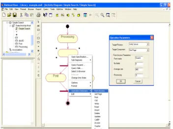
Internal actions are illustrated by a UML activity diagram which appears, as shown in figure 3, when selecting the corresponding name from a menu that opens up when right clicking on a component use case. Actions included in this activity diagram are selected from the operation dictionary through a submenu (figure 4). Depending on the operation selected, a form appears containing the parameters of the specific operation. Through this form, the system designer may specify a value for every parameter.
Figure 4: Process Component Representation In figure 4, the UML activity diagram for the Simple
Search component of Web Client process is depicted. The
form_access (form_name, no_fields, avg_fsize,
processing) operation concerns accessing, activating and
processing of a web form. For the operations that invoke other components, the target process component is specified through the same form. This information enables the automatic generation of arrows among components in the external part of the application view when the activity diagram window is closed. Arrows are labeled using the name and the id of the operation initiating process activation.
3.1.2 UML Extensions
Figures 5 and 6 represent UML 2.0 extensions (additional stereotypes are depicted in a shaded manner) defined for the external and internal representation of processes in the Application View.
Packages in UML constitute a general grouping mechanism. Therefore, server and client processes are conceived as packages, as they both group components. They are defined as stereotypes of Package by the name
ProcessPackage. As shown in the figure 3, the
corresponding view elements are rounded rectangles with the corresponding label. Components are conceptually related to use cases, as a use case in UML is a kind of classifier, representing a coherent unit of functionality provided by a system. Thus, the stereotype
ComponentUseCase is defined as a specialization of
UseCase. The stereotype Invokes concerns the
relationship among components. If, for example, component Simple Search invokes component Get Page
(figure 3), it is entailed that Simple Search requires Get Page in order to be accomplished. This implies a dependency relationship among operations, as opposed to use cases in UML use case diagrams which may be connected to each other only by Extend, Include and
Generalization relationships. Thus, we have defined
Invokes relationship as a stereotype of UML Dependency
and more specifically of Usage. Usage is a kind of dependency in which one element requires another for its full implementation. This is exactly the case with the relationship between components. The stereotype Invokes
includes two additional attributes, namelythe operationId
and the operationName, i.e. the id and name of the internal action that initiates the invocation.
Usage RedefinableElement Classifier <<UseCaseModel>> UseCase <<Invokes>> <<ApplicationView>> Model Element Dependency 1..* * +supplier 1..* +supplierDependency * 1..* * +client 1..* +clientDependency * Actor Package <<UserProfileActor>> <<ProcessPackage>> ActivityNode <<ComponentInterfaceUseCase>>
Figure 5: Use Case Diagram Extension to represent the Application View
The stereotype UserProfileActor is a specialization of the Actor classifier of the UML meta-model with additional properties, as activationProbabilities. ApplicationView,
formed of ProcessPackages, UserProfileActors,
ComponentUseCases and Invokes relationships among
them, constitutes a stereotype of Model. Component implementation is represented through an activity graph, hence the relation between ActivityNode and
ComponentUseCase in figure 5.
Each component implementation maps to a UML activity with the differentiation that it is not composed of activities in general, but specifically of operations that have been defined in the Operation Dictionary (figure 6).
ComponentImplementation is formed of
OperationActivities. The stereotype OperationActivity
extends the semantics of ActivityNode with the additional properties valueList and targetProcessComponent. These properties have been described in the previous section (see § 3.1.1).
Figure 6: Activity Graph Extension to represent Component Implementation
3.2 Site View
Defining the access points of the system is supported through the site concept. The term site is used to characterize any location (i.e. a building, an office, etc.). As such, a site is a composite entity which can be further analyzed into subsites, forming thus a hierarchical structure. User profiles and processes are associated with atomic sites, i.e. sites which cannot be further decomposed, constituting therefore the lowest level of the hierarchy. In essence, the hierarchy indicates where (in which location) each process instance runs and each user profile is placed.
The site view is represented using UML component diagrams. Introducing progressive site refinement and linking site range to network range, enables the identification of dependencies between application configuration and network topology. Thus, component diagrams representing site view and deployment diagrams representing physical view are interrelated. This is facilitated by the relationship between node and component model entities already supported in core UML meta-model.
3.2.1 Representation Model
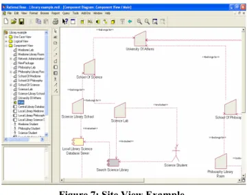
As indicated in figure 7, sites are modeled using UML packages. At the lowest level, server and client processes are illustrated as UML components, the shaded ones standing for client processes, while UML actor icon is used to represent user profiles.
UML dependencies are used to represent relationships among processes (i.e. between UML components in this view), between a user profile and a process, and among sites of different level, while connections between sites and processes or user profiles are illustrated using Include
relationships (arrows with a solid line).
The system designer may specify the number of replicas used for each process through the
numberOfInstances property. For a user profile, this
property indicates the number of users of the specific category (e.g. students) working in a particular site. This information may be entered by the system designer through an appropriate tab included in component specification appearing when double-clicking it.
Figure 7: Site View Example 3.2.2 UML Extensions
The hierarchical site structure indicates a grouping of sites when moving from lower levels to the root of the hierarchy. As such, we have defined site as a stereotype of Package, named SitePackage (figure 8). SitePackages
relate to each other through an Abstraction relationship, a dependency which relates two elements or sets of elements representing the same concept at different levels of abstraction. Sites constitute a more detailed view of their parent site, while root site is the most abstract one.
Figure 8: Component Diagram Extension to represent the Site View
Processes are modeled as UML components, since they are essentially pieces of software. Hence,
ServerComponent and ClientComponent are defined as
stereotypes of UML Component. ServerComponents and
ClientComponents are connected through Dependency
relationships, like components in the respective UML diagrams. These stereotypes extend the semantics of Component by including the additional attribute
numberOfInstances. User profile has been defined as a
stereotype of Actor, named UserProfileActor, including the same attribute.
SitePackages are related to ServerComponents,
ClientComponents and UserProfileActors by Include
relationships. SitePackages, ServerComponents,
ClientComponents and UserProfileActors, along with
their interrelations, compose a SiteView which is itself a stereotype of Model.
4. CONCLUSIONS
We proposed a UML profile, enabling a holistic approach for distributed system configuration. The alternative views supported ultimately result in a consistent distributed system representation which allows efficient system configuration and guarantees system performance. Application view provides for a coherent representation of system functionality. Physical and Site views facilitate progressive process/data allocation taking into account dependencies between network infrastructure and application architecture. The representation of distributed systems concepts as UML model entities contributes considerably to the simplification of model extension/customization, since system designers are usually familiar with UML constructs. We currently further elaborate the Rational Rose add-ins and implement the XML converters in all the tools automating configuration stages.
5. REFERENCES
[1] Armstrong E., et al., The J2EE 1.4 Tutorial, Sun
Microsystems, 2004.
[2] BEA, BEA WebLogic Application Server 8.1 Overview,
White paper, 2003.
[3] Gomaa H., Menasce D., Kerschberg L., “A Software Architectural Design Method for Large-scale Distributed
Information Systems”, Distributed System Engineering
Journal, Vol. 3, No 3, IOP, 1996.
[4] Gomaa H. and Shin M., “Multiple View Meta-Modeling
of software Product Lines”, in Proceedings of the 8th
International Conference on Engineering Complex Computer Systems, IEEE Computer Press, 2002.
[5] Graupner S., Kotov V., Trinks H., “A Framework for Analyzing and Organizing Complex Systems”, in
Proceedings of the 7th International Conference on
Engineering Complex Computer Systems, IEEE Computer Press, 2001.
[6] Kaehkipuro P., “UML-Based Performance Modeling Framework for Component-Based Distributed Systems”,
Lecture Notes in Computer Science 2047, Performance Engineering, Springer-Verlag, 2001.
[7] Law A.M. and McComas M. G., “Simulation Software of Communications Networks: The State of the Art”, IEEE
Communications Magazine, Vol 4, No 3, IEEE Computer Press, 1994.
[8] Mirandola R, Cortellessa V., “UML Based Performance
Modeling in Distributed Systems”, Lecture Notes in
Computer Science 1939, UML2000, Springer-Verlag,
2000.
[9] Natis Y., Pezzini M. Iiyima K., Magic Quadrant for
Enterprise Application Servers, 2004, Research Note, Gartner Research, 2004.
[10] Nezlek G.S., Hemant K.J., Nazareth D.L., “An Integrated Approach to Enterprise Computing Architectures”,
Communications of the ACM, Vol 42, No 11, ACM
Press,1999.
[11] Nikolaidou Μ., D. Lelis, D. Mouzakis, P. Georgiadis, “A
Discipline Approach towards the Design of Distributed
Systems”, Distributed System Engineering Jοurnal, Vol.
2, No 2, IOP, 1995.
[12] Nikolaidou M., D. Anagnostopoulos, “Exploring Web-based Information System Design: A Discrete-Stage
Methodology and the Corresponding Model”, Lecture
Notes on Computer Science 2681, Advanced Information Systems Engineering (CAISE’03), Springer Verlag, 2003. [13] Nikolaidou M. and Anagnostopoulos D., "A Distributed
System Simulation Modelling Approach", Simulation
Practice and Theory Journal, Vol. 11, No 4, Elsevier Press, 2003.
[14] Nikolaidou M., D. Anagnostopoulos, “Web-Based System Engineering: Web-Based Application Configuration Based Upon Restrictions Imposed By Network Architecture”,
Proceedings of 16th Conference on Intelligent and
Adaptive Systems and Software Engineering (IASSE 2003), ISCA, 2003.
[15] OMG Inc, OMG Unified Modeling Language
SuperStructure Specification, Version 2.0, October 2004.
[16] Oracle Co, Oracle Application Server 10g: High
Availability, Oracle White Paper, January 2004.
[17] Rational Software Corp, Using the Rose Extensibility Interface, White Paper, 2001.
[18] Savino-Vázquez N.N. et al., “Predicting the behaviour of three-tiered applications: dealing with distributed-object
technology and databases”, Performance Evaluation Vol.
39, no 1-4, Elsevier Press, 2000.
[19] Shedletsky J. and Rofrano J., “Application Reference
Designs for Distributed Systems”, IBM System Journal,
Vol. 32, No 4, 1993.
[20] Serain D., Middleware, Springer-Verlag London, Great
Britain, 1999.
[21] Willenborg R., Brown K., Cuomo G., “Designing WebSphere Application Server for performance: An evolutionary approach”, IBM System Journal, Vol 43, No 2, 2004.