1
Performance and Evaluation
OfMicrocontroller based Multilevel Sun
Tracking Solar Photo Voltaic System
A Thesis submitted to the
Dept. of Electrical & Electronic Engineering, BRAC University
in partial fulfillment of the requirements for the
Bachelor of Science degree in Electrical & Electronic Engineering
Tania Ahmed
SyedaEshita Ashraf
MasruraTamanna
2
Declaration
We do hereby declare that the thesis titled ―Performance and Evaluation Of Multilevel Solar Panel Photo Voltaic System‖ submitted to the Department of Electrical and Electronics Engineering of BRAC University in partial fulfillment of the Bachelor of Science in Electrical and Electronics Engineering, is our original work and was not submitted elsewhere for the award of any other degree or any other publication.
Date: Supervisor __________________________________ DrMdMosaddequr Rahman __________________________ Tania Ahmed Student ID: 10221058 __________________________ SyedaEshita Ashraf Student ID: 10121057 __________________________ MasruraTamanna Student ID: 10221019
3
Acknowledgement
We would like to extend our profound gratitude to our thesis advisor Dr. MD. Mosaddeque Rahman Associate Professor, BRAC University, who has blessed us with his kind assistance and dedicated involvement in every step throughout the accomplishment of this paper. We are deeply grateful for his help, professionalism, valuable guidance and encouragement throughout the course of this work. Moreover, we would like to thank our parents and friends for inspiring us.
4
Abstract
Solar energy systems have emerged as a viable source of renewable energy over the past two or three decades, and are now widely used for a variety of industrial and domestic applications. Such systems are based on a solar collector, designed to collect the sun’s energy and to convert it into either electrical power or thermal energy. Solar energy is predictable to play a great role in the infrastructure as a distributed source, due to the fact that it is an easily available renewable source of energy. In a country like Bangladesh where electricity generation has become an immense job since it has been suffering from a huge crisis despite of the fact that several natural grid has been added to the national power grid but still it is not enough. The country lags behind than its expected production capacity. The main focus of the project is to design and implement a system sufficient enough to generate electricity, take less space and will be highly efficient for urban areas in Bangladesh. Solar tracking system is the most appropriate technology to enhance the efficiency of the solar cells by tracking the sun. A microcontroller based design methodology of an automatic solar tracker is presented in this paper. The proposed system comprises of three panels stacked one upon another at a fixed distance from each other so that the overall system ends up with a minimum space which is suitable for urban areas that has very low floor space. The panels are supported by a metal rod fixed at tilt angle equal to the latitude among north-south direction facing north-south. (23°) The panels rotate throughout the day from sunrise to sunset via motors equipped with them controlled by microcontroller which enables rotation of the three panels at hourly intervals on a fixed horizontal axis to track the sun and maximize power generation. The system escorted by an actuator that changes the entire position of the three panels after midday when the sun moves toward west. The anticipated system will provide a useful solution to electricity problems in urban areas where space is limited.
5
T
able of
C
ontents
ACKNOWLEDGEMENTS ... 3 ABSTRACT ... 4 TABLE OF CONTENTS………5 FIGURE LIST ... 7 1. INTRODUCTION ………..1 1.1 MOTIVATION... 1 1.2 PROJECT OUTLINE ... 1 1.3 PROJECT OBJECTIVE ... 21.4 SCOPE OF THE PROJECT ... 3
2 SYSTEM DESCRIPTION ... 11
2.1 PHOTOVOLTAICTECHNOLOGY ... 11
2.2 SOLAR PANELS... 12
2.3 SERVOMOTOR ... 14
2.4 POLULUMINIMAESTRO ... 16
2.5 ARDUINO8 ... Error! Bookmark not defined.8 2.51 ARDUINO UNO ... Error! Bookmark not defined.9 2.52 ARDUINO MEGA ... Error! Bookmark not defined. 2.53 WHY ARDUINO MEGA IS SUITABLE FOR OUR SYSTEM?Error! Bookmark not defined. 2.54 WHYARDUINOMEGAUNSTEADOFMICROCONTROLLER?ERROR!BOOKMARK NOT DEFINED. 2.55 REAL TIME CLOCK(RTC) ... Error! Bookmark not defined. 2.56 WIRING IT UP WITH ARDUINO ... Error! Bookmark not defined. 2.57 BATTERY ... 25
2.58 BATTERY HOLDER ... Error! Bookmark not defined. 2.59 ACTUATOR ... ERROR!BOOKMARK NOT DEFINED. 2.60 RELAY BREAKOUT BOARD ... Error! Bookmark not defined. 2.61 CRYSTAL ... Error! Bookmark not defined. 2.62 SUN TRACKER ... 21
2.63 NEEDOFASUNTRACKER ... 22
2.64 SOLARTRACKERFUNDAMENTALS ... 29
2.65 DIFFERENTTYPESOFTRACKING ... 22
2.66 TYPESOFSOLARTRACKER ... 32
3 CALCULATION FOR SYSTEM SIZE ... 37
3.1 INTRODUCTION ... 37
3.2 SOLARPANELCALCULATION ... 37
3.21 SOLARMODULETYPICALPERFORMANCECHARACTERISTICS ... 38
3.3 CALCULATINGTHEDISTANCEBETWEENPANELS ... 39
3.4 SOLARANGLECALCULATION ... 40
3.5 CALCULATIONOFSUNRISEANDSUNSETTIMEERROR!BOOKMARK NOT DEFINED.
6
4.1 INTRODUCTION... 42 4.2 CONTROL CIRCUIT DIAGRAM ... ERROR!BOOKMARK NOT DEFINED.
5 SOFTWARE IMPLEMENTATION ... 49
6 CONCLUSION ... ERROR! BOOKMARK NOT DEFINED.4
7
Figure List
Figure 1: Initial Position of the system……… ……….….9
Figure 2: I-V and P-V characteristics of photovoltaic cells……….….………..13
Figure 2.1: Types of solar panel... 15
Figure 3: Servo Motor…………... 15
Figure 4: How the servo motors are connected with the solar panels in oursystem.………...…..16
Figure 5: Pin diagram of Mini Maestro 12……….………..…...17
Figure 5.1: Arduino (a) Arduino Uno (b) Arduino Mega ………..……17
Figure 6: The connection of the real time clock with the Arduino………..…… …18
Figure 7: A 3V lithium battery……….……….….…….19
Figure 8: Battery holders……….…..…..20
Figure 9: An electronic actuator in our system………...25
Figure 10: Relay and its symbol………..……….……...30
Figure 11: The relays used in our system …………..………...34
Figure 12: Crystal………...39
Figure 13: AC plug in charger……….40
Figure 14 Block Diagram of the charge controller circuit……….…...41
Figure 153Watt Solar Panels……….…...42
Figure 16: Finding distance between two panels………... ...44
Figure 17:Solar angles used in power calculations for PV panels………..…………...46
Figure 18:The time correction EoT is plotted in the figure below………..………… ...46
Figure 19: The block diagram of the operation of the whole proposed system……….………...46
Figure 20: The circuitry of our proposed system………...46
Figure 21: Empty sketch book of the Arduino 1.0.3 version ………...……….………...46
8
CHAPTER 1
Introduction
1.1 Motivation
Energy is the major factor for the development of a nation. A massive amount of energy is extracted, distributed, converted and consumed in the global society daily. 85% of energy production is dependent on fossil fuels.With extensive growth of population, Bangladesh is facing an acute shortage of electricity. Since urban areas are densely populated with high rising buildings with minimal space left and hence setting up photovoltaic system is quite a big hassle. Our system approaches a sensible solution to this problem. The design of setting up panels one top of another reduces system space and allows several systems to be installed in parallel. The position of Bangladesh is between 20.30 - 26.38 degrees north and 88.04 - 92.44 degrees east which is an ideal location for solarenergy consumption. In our country 4 to 6.5 KWh per square meter and maximum amount of radiation is available in summer. Therefore Bangladesh is the suitable place for installation and experimenting our system efficiently.
1.2 Project Outline
The project is about designing a system that will automatically track sun and convert it into solar power from sunrise to sunset. Each of the panels is equipped with a servo motor which in turn is controlled by the microcontroller in the Arduino. The Arduino Mega is a microcontroller board based on the ATmega1280. It has 54 digital input/output pins (of which 14 can be used as PWM outputs), 16 analog inputs, 4 UARTs (hardware serial ports) and a 16 MHz crystal oscillator. The panels are initially set at 7.5 degree facing east. This is due to the fact that the sun moves 15° in the sky at sunrise and microcontroller sends signal to the servo motors to rotate the panels by 15° as well. As a result the panels will be a total of 7.5° ahead of the sun and each time the sun moves by 15°, the panels will be rotated by another 15°. From sunrise to sunset the panels will be rotated 11 times from 7.5 degree to 172.5 degree in discreet levels of 15 from east to west. All these mechanisms are controlled by Arduino. Here we have used The Mini Maestro which is a highly versatile (and compact) servo controller and general-purpose I/O boards. Mini Maestro
9
controls and provides power to the three servo motors making this servo controller well suited for high-precision animatronics, and built-in speed and acceleration control make it easy to achieve smooth, seamless movements without requiring the control source to constantly compute and stream intermediate position updates to the Mini Maestro. At sunset the panels will be reset to their original position for the next day along with the actuator.
When the sun reaches the angle of ϕ, the angle at which maximum exposure from the sun is achieved by both the top and lower panels without being shaded by one another. The system is incorporated with a linear actuator which determines the position of the system when the sun passes its maximum angle at noon. The actuator shifts the entire system to the opposite side thus the top and bottom panel gets maximum exposure. The middle panel is deactivated keeping it in vertical position until the sun moves past the zenith towards west. This position avoids shading of the bottom panel.
The entire system will not operate continuously rather it will track the sun by rotating the panels at discreet steps 11 times a day by 15°. However, the panels will track sun continuously as a result of which there will be a 1% loss to the energy production of the total incident energy. Furthermore, the servo motors will operate a small fraction of the total time and hence energy consumption is very low probably a small fraction of the total energy used by the system.
10
1.3 Scope of the Project
The scope of the project is to construct a prototype of three panels one upon another at fixed distance connected to servo motors. The various components required in designing the prototype of the system includes Arduino, Mini Maestro (motor shield), RTC(Real Time Clock), Relay Break out board, 12V actuator and battery for power supply. All the named components are controlled by programming from the microcontroller in the Arduino.
1.4 Project Objective
As technology is advancing the consumption of power is steadily rising, as a result sufficient and reliable source of electricity is a major prerequisite for a living standard and prosperity of a nation. Present generation of electric power in Bangladesh is not sufficient to meet the consumers growing demand. So it is not possible to ensure a constant supply of electric power to all consumers throughout the country. As long as our earth exists, the sun is there to give us unlimited solar energy. It is completely up to us how we are going to utilize this abandonedenergy.Every hour, sun gives the same amount of energy to the world that the whole world uses in an entireTherefore we could use this vast amount of resources by implementing solar photo-voltaic systems. But the conventional PV modules are less efficient and they require a lot of floor space. In urban areas the energy demand is sky high but there is a shortage of space as most of the buildings arenow high-rise apartments. So space is a major concern for setting up solar PV modules in urban areas where rooftop space is small. For solving this problem this paper describes a way for setting up PV modules in a modern and scientific way.
11
CHAPTER 2
System Description
Introduction
The proposed system consists of solar panels mounted one top of another. Each of the panels is connected with servo motors driven by microcontroller built in Arduino. The sun tracking system starts with a Real Time Clock that calculates time, the clock/calendar provides seconds, minutes, hours, day, date, month, and year information. The microcontroller reads time from RTC and compares the sunrise and sunset times from the set of equation fed into the microcontroller and sends signal to the motor to rotate the panels. The actuator is activated around midday after the sun passes the angle ϕ which is the maximum position for the upper and lower panels for full exposure. At sunset the whole system resets coming back to its original orientation via the actuator.
2.1 Photovoltaic Technology
The most abundant and convenient source of renewable energy is solar energy, which can be harnessed by photovoltaic cells. Photovoltaic cells are the basic of the solar system. The word photovoltaic comes from ―photo‖ means light and ―voltaic‖ means producing electricity.
Therefore, the photovoltaic process is ―producing electricity directly from sunlight‖. The output power of a photovoltaic cell depends on the amount of light projected on the cell. Time of the day, season, panel position and orientation are also the factors behind the output power. The current-voltage and power-voltage characteristics of a photovoltaic cell are shown in the Figure below:
12
Figure: 2 I-V and P-V characteristics of photovoltaic cells
2.2 Solar Panels
A solar cell (also called a photovoltaic cell) is an electrical device that converts the energy of light directly into electricity by the photovoltaic effect. It is a form of photoelectric cell, defined as a device whose electrical characteristics—e.g. current, voltage, or resistance—vary when exposed to light. If a number of photovoltaic cells are assembled together it forms solar modules which generate electrical power from sunlight. Multiple cells in an integrated group, all oriented in one plane, constitute a solar photovoltaic panel.
The efficiency of solar panels goes hand in hand with purity, but the processes used to enhance the purity of silicon are expensive. Since electricity generation efficiency and space efficiency is our primary concern we should select such a solar panel which will best suit these two major requirements. Cost is also a major factor to be considered.
There are a number of different types of solar panels and there are differences between these various types of panels, that are worth knowing about but, in the end, it is the total overall power that makes the biggest difference. There are mainly three different types of solar panels namely
13
1.Monocrystalline Silicon Solar Cells
2. Thin-Film Solar Cells (TFSC) (Amorphous Silicon Solar Cells)
3. Polycrystalline Silicon Solar Cells
Figure: 2.1 (a) Monocrystalline solar cells; (b) Polycrystalline solar cells; (c) Amorphous solar cells
a
Monocrystalline solar cells are made out of silicon ingots, which are cylindrical in shape. Monocrystalline solar panels have the highest efficiency rates since they are made out of the highest-grade silicon and Monocrystalline silicon solar panels are space-efficient but Monocrystalline solar panels are the most expensive. Since cost efficiency is one of the major factors to be considered so it does not make it suitable for the system to be designed.
Because the output of electrical power is low, solar cells based on amorphous silicon have traditionally only been used for small-scale applications such as in pocket calculators. However, recent innovations have made them more attractive for some large-scale applications too. Using amorphous silicon mass production is simple but amorphous solar panels are in general not very useful for in most residential situations. They are cheap, but they also require a lot of space and the efficiency of amorphous modules to convert sunlight to electricity is half of polycrystalline or mono crystalline panels so it is not a good choice to choose amorphous silicon for the system to be implemented.
Recent advantages in the polycrystalline solar panels have made them more and more similar in efficiency as their Monocrystalline brother. There greatest advantage is that they usually come at
14
a smaller price and are efficient panels and don’t have problems with shade from buildings or nearby trees. Since the maximum efficiency is one of the major aims of our system and in urban areas shades from neighboring building is a common problem it is strongly recommended to use polycrystalline solar panel for our system to be designed.
2.3 Servo Motor- MG995
Servo refers to an error sensing feedback control which is used to correct the performance of a system. This is a powerful, low-cost, reliable, simple, high quality continuous full-rotation servo motor. This servo is able to take in 6 volts and deliver 66.7 oz-in. of maximum torque at 70r/min. They are equipped with a servo mechanism for precise control of angular position. The RC servo motors usually have a rotation limit from 90° to 180°. Some servos also have rotation limit of 360° or more. But servos do not rotate continually. Their rotation is restricted in between the fixed angles. We are using three servo motors in our system. The servo motors are not directly connected to the arduino but to the pololuminimaestro 12. The pololu will run the three servo motors of our system.
Features:
Voltage: 4.8-6.0 Volts
Torque: 45.8/66.7 oz-in. (4.8/6.0V)
Speed: 60/70 r/min (4.8/6.0V)
Rotation: 360°
Dual Ball Bearing
4 Plastic Gears + 1 Metal Gear
25T Spline
15
(a) (b)
Figure: 3 (a) A MG995 servo motor (b) the parts of the servo motor
The servo connector has three wires - Brown, Red and Orange. Brown connects to the ground of the Arduino. Red connects to the 5V on the Arduino. Orange connects to the I/O pin on the Arduino, in this case digital pin 9. Jumper wires are used to connect between the female connectors on the servo cable and Arduino headers.
16
In our project three servo motors are used for rotating three solar panels. The sun rises in the east and sets in the west. Similarly our project will start working from east and will stop at west. Initially the three solar panels are oriented and inclined facing east when the servo motor willstart working it will rotate the panel 15 degree stepwise from east to west in 12 times. When the sun sets the system will stop working as well as the servo motor.
2.4 Pololu Mini Maestro
The Mini Maestros are highly versatile (and compact) servo controllers and general-purpose I/O boards. They support three control methods: USB for direct connection to a computer, TTL serial for use with embedded systems and internal scripting for self-contained, host controller-free applications. The channels can be configured as servo outputs for use with radio control (RC) servos or electronic speed controls (ESCs), as digital outputs, or as analog/digital inputs.
A free configuration and control program is available for Windows and Linux, making it simple to configure and test the device over USB, create sequences of servo movements for animatronics or walking robots, and write, step through, and run scripts stored in the servo controller. The extremely accurate, high-resolution servo pulses have a jitter of less than 200 ns, making this servo controller well suited for high-precision animatronics, and built-in speed and acceleration control make it easy to achieve smooth, seamless movements without requiring the control source to constantly compute and stream intermediate position updates to the Mini Maestro.
However, there are number of pololu mini maestro with different number of channels such as:
1. Micro Maestro 6
2. Mini Maestro 12-Channel USB Servo Controller
3. Mini Maestro 18-Channel USB Servo Controller
17
In our system we have chosen Mini Maestro 12-channels USB Servo Controller which can run 12 servo motors. For the three panels we have to run three motors so we have used mini maestro12. High current flows is required to run the servos so this high current supply is provided by the mini maestro because Arduino will get damaged if it is to provide this current.
Using mini maestro wiring of the system is also reduced and it is easier to make the programming by addressing the specific pin numbers in the program to run the specific servo.
18
Connection of mini maestro with the Arduino is shown below:
2.5 Arduino
An Arduino board consists of an Atmel 8-bit AVR microcontroller with complementary components to facilitate programming and incorporation into other circuits. The board contains everything that a midsized 8bit microcontroller project needs. The key point of the whole Arduino hype is the IDE and loads of libraries available for an easy start and the boot loader. An important aspect of the Arduino is the standard way that connectors are exposed, allowing the CPU board to be connected to a variety of interchangeable add-on modules known as shields. Some shields communicate with the Arduino board directly over various pins, but many shields are individually addressable via an I²C serial bus, allowing many shields to be stacked and used in parallel.
There are basically two different types of Arduino boards. They are:-
2.51Arduino Uno
The Arduino Uno is a microcontroller board based on the ATmega328. It has 14 digital input/output pins (of which 6 can be used as PWM outputs), 6 analog inputs, a 16 MHz ceramic resonator, a USB connection, a power jack, an ICSP header, and a reset button. It contains
19
everything needed to support the microcontroller; simply it can be connected to a computer with a USB cable or powered it with an AC-to-DC adapter or battery to get started.
2.52Arduino Mega
The Arduino Mega is a microcontroller board based on the ATmega1280. It has 54 digital input/output pins (of which 14 can be used as PWM outputs), 16 analog inputs, 4 UARTs (hardware serial ports), a 16 MHz crystal oscillator and the rest of the parts of arduino mega is similar to arduinouno.
(a) (b)
Figure: 5.1(a) Arduino Uno. (b) Arduino Mega
Features ATmega 2560 @ 16MHz Selectable 5V/3.3V operation 70 Digital IO 16 Analog inputs 14 PWM outputs
4 Hardware serial ports (UART)
Compatible with most Arduino Duemilanove and Diecimila Shields
Small form factor, 30% smaller than Arduino Mega
Easy to program, no additional hardware is required to load firmware – just plug to a USB port and you’re good to go.
ICSP Header
20
Application Ideas
LED display/LCD controller
Pulse width modulation driver
Robot controller
Data acquisition systems
Alarm systems
Programmable logic controllers
Embedded Web servers
Control Systems
2.53Why Arduino Mega is suitable for our system?
Obviously we will not select a device that pushes the limits, but sometimes the regular Arduino Uno seems a bit, well, cramped. We might have trouble finding a spare pin to connect to, or memory just seems to be short all the time. Pins are the first thing we would see. The Arduino Uno has 20 I/O pins, while the Mega has 70. Memory is one of the major factor where Arduino Uno has 32 KB flash memory (program storage), 2 KB SRAM (scratchpad/working memory), and 1 KB EEPROM (permanent variable storage). Arduino Mega has 256 KB flash, 8 KB SRAM, and 4 KB EEPROM which is big difference in memory.
Hardware versus Software is another area of difference. The Mega has four hardware serial ports, which means maximum speed if we need a second or third (or fourth) port. On the Uno, we can do similarly using the NewSoftSerial Library; however, software is slower, and if our program is pushing the limits, we may find a hardware serial port more useful. Mega can run more powerful softs and run for longer time before overheat the cooler.
2.54 Why Arduino instead of Microcontroller 8051?
Arduino and 8051 are no comparison to say. Because one is a microcontroller and other is a development platform. Arduino runs (rather originally) on Atmel's AVR microcontroller series. The main differences are major differences in the architecture of the controllers. But to say on a more user based view, AVR is more peripheral rich it has in-built ADC and several timer based peripherals and it’s easier to program as compared to microcontroller. Using an Arduino
21
simplifies the amount of hardware and software development we need to do in order to get a system running. The Arduino hardware platform already has the power and reset circuitry setup as well as circuitry to program and communicate with the microcontroller over USB.
On the software side, Arduino provides a number of libraries to make programming the microcontroller easier. The simplest of these are functions to control and read the I/O pins rather than having to fiddle with the bus/bit masks normally used to interface with the Atmega I/O (This is a fairly minor inconvenience). More useful are things such as being able to set I/O pins to PWM at a certain duty cycle using a single command or doing Serial communication. Arduino is hobbyist friendly and 8051 is Industry Friendly. Not everyone wants to work on low end platform like 8051.
Arduino is capable of engaging people with a less technical background to be engaged in electronics. Arduino has a very high speed and ease of development. The open source nature of Arduino has led to the availability of dozens of "shields" (i.e. daughter cards) that facilitate such things as Internet access, wireless networking, data logging, and devicecontrol. Another big
advantage is the Arduino IDE which allows software development on all major
platforms (Mac, PC, and Linux) with an easy-to-use subset of C/C++.
2.55 Real Time Clock (DS1307)
The DS1307 serial real-time clock (RTC) is a low-power, full binary-coded decimal (BCD) clock/calendar plus 56 bytes of NV SRAM. Address and data are transferred serially through an I²C, bidirectional bus. The clock/calendar provides seconds, minutes, hours, day, date, month, and year information. The end of the month date is automatically adjusted for months with fewer than 31 days, including corrections for leap year. The clock operates in either the 24-hour or 12-hour format with AM/PM indicator. The DS1307 has a built-in power-sense circuit that detects power failures and automatically switches to the backup supply. Timekeeping operation continues while the part operates from the backup supply.
22
Key Features
Real-Time Clock (RTC) Counts Seconds, Minutes, Hours, Date of the Month, Month, Day of the week, and Year with Leap-Year Compensation Valid Up to 2100
56-Byte, Battery-Backed, General-Purpose RAM with Unlimited Writes
I²C Serial Interface
Programmable Square-Wave Output Signal
Automatic Power-Fail Detect and Switch Circuitry
Consumes Less than 500nA in Battery-Backup Mode with Oscillator Running
Optional Industrial Temperature Range: -40°C to +85°C
Available in 8-Pin Plastic DIP or SO
In our project we have used (DS1307) wired with Arduino to give the proper sunrise and sunset times. The real time clock is provided with a 3v lithium battery source.
2.56 Wiring It Up with the Arduino
There are only 5 pins in the real time clock: 5V GND SCL SDA SQW.
5V is used to power to the RTC chip when we want to query it for the time. If there is no 5V signal, the chip goes to sleep using the coin cell for backup.
GND is common ground and is required
SCL is the i2c clock pin - its required to talk to the RTC
SDA is the i2c data pin - its required to talk to the RTC
SQW is the optional square-wave output we can get from the RTC if we have configured it to do so.
23
Figure: 6 The connection of the real time clock with the Arduino
2.57 BATTERY, LITHIUM CR2025 3V:
Specification Battery Capacity-220mAh,
Battery IEC Code-CR2025, Battery NEDA Code-5004LC,
Battery Size Code-2032,
Battery Technology-Lithium Manganese Dioxide,
Battery Terminals-Pressure Contact Battery Voltage:3V
External Diameter:20mm
External Height:3.2mm Weight:3g
24 External Length / Height:3.2mm
Output Voltage:3VFigure:7A 3V lithium battery
2.58 Battery Holder:
Body: FR-nylon with 15% glass filled
Contact:
o Electrode/phosphor bronze
o Electrode/brass
Contact: tin 100 micron plated over ni 30 micron under-plating
Application for 3V lithium battery
Insulator resistance: 1,000mW/min
Operation temperature: +55 to +105oC
Durability: 50 cycles minimum
25
Figure: 8Battery holders
2.59 Actuator
An actuator is a type of motor that is responsible for moving or controlling a mechanism or system.
It is operated by a source of energy, typically electric current, hydraulic fluid pressure, or pneumatic pressure, and converts that energy into motion. An actuator is the mechanism by which a control system acts upon an environment. The control system can be simple, software-based, a human, or any other input.There are varieties of actuators and they are Mechanical actuators, Hydraulic actuators,Pneumatic actuators, Electro-mechanical, Linear motor etc. In our system we have used linear actuator because linear actuatorcreates motion in a straight line, in contrast to the circular motion of a conventional electric motor.
Advantages and disadvantages:
Actuator Type Advantages Disadvantages
Mechanical actuators
Cheap repeatable, no power source required, self-contained, identical behavior extending or retracting.
Manual operation only. No automation.
26
The main role of the actuator in our system is to move our whole system back and forth in a day. Initially the actuator remains inactive from the morning to the noon. When it is noon the actuator becomes active and shifts the whole system to just opposite alignment compared to its initial position. Initially the panels remain in such a position to capture maximum sunlight so the actuator operation is not required here. At noon when the sun is just at the top of the system the panels do not receive much energy so the actuator needs to shift the system towards its opposite direction to get the full exposure of the sunlight to the panels.
The actuator in our system will be provided with power from a battery source rather than a power source because the power rating of the actuator is huge which is 12V compared to the power rating of other components used. It is seenthat when the actuator is getting power supply from the power source the real time clock in our system gets reset. The real time clock gets its power from a lithium battery and is grounded to a common point where all the components are grounded. The real time clock gets reset because its power rating is small and when this huge power flows through it real time clock gets reset.
Hydraulic actuators
Very high forces possible.
Can leak. requires position feedback for repeatability. External hydraulic pump
required. Some designs good in compression only.
Linear motor
Simple design. Minimum of moving parts. High speeds possible.
Self-contained. Identical behavior extending or retracting.
Low to medium force.
Electro-mechanical
Cheap. Repeatable. Operation can be automated. Self-contained. Identical behavior extending or retracting. DC or stepping motors. Position feedback possible.
Many moving parts prone to wear.
Pneumatic
actuators Strong, light, simple, fast. Precise position control impossible except at full stops
27
When the actuator in active it creates magnetic flux around it so the interference between the magnetic flux and the electric flux also reset the real time clock and this interference also causes problems to other circuitry of the system so the entire actuator operation and circuitry is separated from the whole system.
Figure:9An electronic actuator in our system
2.60 6V Relay Breakout Board
A relay is an electrically operated switch. Current flowing through the coil of the relay creates a magnetic field which attracts a lever and changes the switch contacts. The coil current can be on or off so relays have two switch positions and they are double throw (changeover) switches. The relay’s switch connections are usually labeled COM (POLE), NC and NO. The operating voltage of relay is 6v.
COM/POLE= Common, NC and NO always connect to this; it is the moving part of the switch.
28
NO = Normally Open, COM/POLE is connected to this when the relay coil is MAGNETIZED and vice versa.
A relay shown in the picture is an electromagnetic or mechanical relay.
Figure: 10Relay and its symbol
There are 5 Pins in a relay. Two pins A and B are two ends of a coil that are kept inside the relay. The coil is wound on a small rod that gets magnetized whenever current passes through it.COM/POLE is always connected to NC (Normally connected) pin. As current is passed through the coil A, B, the pole gets connected to NO (Normally Open) pin of the relay.
In our system the two relays are used to toggle the positive and negative power to the actuator in order to determine the direction of piston travel. 12v power supply is given to the NC pin and the NO pin is grounded when the actuator is inactive. When NC pin is grounded and NO pin is given 12v the relay switch is pressed and the code reads the current position, and then determines which direction to drive the piston to reach the goal position. Once the goal position is reached it shuts off the power to the motor.
29
Figure: 11The relays used in our system
2.61 Crystal 32.768KHz
The DS-crystal-series are tubular metal-can packages in the standardized Watch-crystal sizes DS26 = ∅ 2 x 6.0 mm, DS15 = ∅ 1.5 x 5.0 mm and DS10 = ∅ 1 x 4.3 mm for thru-hole applications. Within the package is a high-quality tuning fork quartz crystal resonator, manufactured with precision high-volume photolithographic process and operating in the fundamental mode at 32.768 kHz.
The crystal has few characteristics such
1. Very small metal-can packages 2. High stability
3. Low aging
4. Low power consumption
5. High shock and vibration resistance
Figure: 12 Crystal
2.62 Sun tracker
A solar tracker is a device that orients a payload toward the sun. Payloads are photovoltaic panels. There are different types of sun trackers. These are used for special purposes. Some of these tracking systems are discussed below:
2.63 Need of a sun tracker:
Each day, the sun rises in the east, moves across the sky, and sets in the west. Whenever the sun is shining on us, it is sending energy in our direction. We can feel the heat from the sun, and we can see objects that are illuminated by the light from the sun as it moves across the sky. However, if we could get a solar cell to turn and look at the sun all day, then it would be
30
receiving the maximum amount of sunlight possible and convert ing it into the more useful energy form electricity y. If we are located in the tropics, we see that the sun appears to follow a path that is nearly directly overhead. However, for locations north or south of the tropics (e.g., latitudes greater than 23.5 degrees), the sun never reaches a position that is directly overhead. Instead, it follows a path across the southern or the northern part of the sky.
2.64 Solar Tracker Fundamentals:
A solar tracker is a device that is used to align a single P.V module or an array of modules with the sun. Although trackers are not a necessary part of a P.V system, their implementation can dramatically improve a systems power output by keeping the sun in focus throughout the day. Efficiency is particularly improved in the morning and afternoon hours where a fixed panel will be facing well away from the sun’s rays. P.V modules are expensive and in most cases the cost of the modules themselves will outweigh the cost of the tracker system. Additionally a well-designed system which utilizes a tracker will need fewer panels due to increased efficiency, resulting in a reduction of initial implementation costs.
2.65 Different types of tracking:
Active trackerThese trackers use motors and gear trains in directing the tracker as commanded by a controller responding to the solar direction. Active two axis trackers are used to orient heliostats. Light sensing type of trackers has two photo sensors, photodiodes, configured differentially so that they output a null when receiving the same light flux. They are supposed to be flat and are 90 degrees apart. Since the motors consume energy, use them only when necessary. Now if the light is below some threshold level, there may not b enough power available for reorientation. Precaution should be taken so as not waste energy during cloudy days when there is not enough light.
Passive tracker
This type of tracker works on the principle of creating a gas pressure by using a low BP compressed gas fluid. This fluid is then driven to one side or the other due to solar heating thus creating gas pressure. This causes the tracker to move in response to an imbalance. These kinds
31
of trackers are provided with Viscous Dampers to prevent excessive motion in response to wind gusts and Shader or Reflectors to reflect the early morning light to start the panel tilting towards the sun.
Open Loop Trackers
Open loop trackers determine the position of the sun using computer controlledalgorithms or simple timing systems.
Altitude / Azimuth Trackers
Use astronomical data or sun position algorithmsto determine the position of the sun for any given time and location. Tracker location, date and time are used by a micro controller to fix the position of the sun. Once the position has been calculated, the modules are moved using servo motors and there position measured by encoders built into the tracker frame. Different types of sun tracker: There are many types of solar trackers, of varying costs, sophistication, and performance.
2.66 Types of Solar Trackers
There are many different types of solar tracker which can be grouped into single axis and double axis models.
Single axis tracker:
Track the sun from east to west using a single pivot point
Increase solar yield up to 34%
Simple, effective design
Low maintenance
Lower cost compared to dual axis
32
Figure: 13 Single Axis Tracker
Horizontal single axis tracker
Single axis horizontal trackers may be oriented by either passive or active mechanisms .In these, a long horizontal tube is supported on bearings mounted upon pylons or frames .The axis of the tube is on a north-south line. Panels are mounted upon the tube , and the tube will rotate on its axis to track the apparent motion of the sun through the day. Since these do not tilt toward the equator they are not especially effective during winter midday(unless located near the equator),but add a substantial of productivity during the spring and summer seasons when the solar path is high in the sky. These devices are less effective at higher latitudes .The principal advantage is the inherent robustness of the supporting structure and the simplicity of the mechanism. Since the panels are horizontal, they can be compactly placed on the axle tube without danger of self-shading and are also readily accessible for cleaning. For active mechanisms, a single control and motor may be used to actuate multiple rows of panels.
Vertical single axis tracker
A single axis tracker may be constructed that pivots only about a vertical axle, with the panels either vertical or at a fixed elevation angle. Such trackers are suitable for high latitudes, where the apparent solar path is not especially high, but which leads to long days in summer, with the sun travelling through a long arc.
Polar aligned single axis trackers
This method is scientifically well known as the standard method of mounting a telescope support structure. The tilted single axis is aligned to the polar star. It is therefore called a polar aligned
33
single axis tracker (PASAT). In this particular implementation of a tilted single axis tracker, the tilt angle is equal to the site latitude. This aligns the tracker axis of rotation with the earth’s axis of rotation.
Tilted single axis tracker
All trackers with axes of rotation between horizontal and vertical are considered tilted single axis trackers. Tracker tilt angles are often limited to reduce the wind profile and decrease the elevated end height. Field layouts must consider shading to avoid unnecessary losses and to optimize land utilization. With backtracking, they can be packed without shading perpendicular to their axis of rotation at any density. However, the packing parallel to their axes of rotation is limited by the tilt angle and the latitude. Tilted single axis trackers typically have the face of the module oriented parallel to the axis of rotation. As a module tracks, it sweeps a cylinder that is rotationally symmetric around the axis of rotation.
Dual axis tracker
:
Track the sun from east to west, and north to south using two pivot points
Increases solar yield up to 37%
Complex design – more motors and sensors
Higher maintenance
Higher cost due to additional parts and installation time
34
Figure: 14 Dual Axis Tracker
Tip–tilt dual axis tracker (TTDAT)
A tip–tilt dual axis tracker is so-named because the panel array is mounted on the top of a pole. Normally the east-west movement is driven by rotating the array around the top of the pole. On top of the rotating bearing is a T- or H-shaped mechanism that provides vertical rotation of the panels and provides the main mounting points for the array. The posts at either end of the primary axis of rotation of a tip–tilt dual axis tracker can be shared between trackers to lower installation costs.Other such TTDAT trackers have a horizontal primary axis and a dependent orthogonal axis. The vertical azimuthal axis is fixed. This allows for great flexibility of the payload connection to the ground mounted equipment because there is no twisting of the cabling around the pole.Field layouts with tip–tilt dual axis trackers are very flexible. The simple geometry means that keeping the axes of rotation parallel to one another is all that is required for appropriately positioning the trackers with respect to one another. Normally the trackers would have to be positioned at fairly low density in order to avoid one tracker casting a shadow on others when the sun is low in the sky. Tip-tilt trackers can make up for this by tilting closer to horizontal to minimize up-sun shading and therefore maximize the total power being collected.The axes of rotation of many tip–tilt dual axis trackers are typically aligned either along a true north meridian or an east west line of latitude.Given the unique capabilities of the Tip-Tilt configuration and the appropriated controller totally automatic tracking is possible for use on portable platforms. The orientation of the tracker is of no importance and can be placed as needed.
35
CHAPTER 3
Calculations of System Size
3.1 Introduction
This part of the chapter explains the calculation of the entire system. Therefore, calculations are now needed to bedonein order todetermine the parameters for aphotovoltaic systemto generate electricity. The systemwill require a solar panel for the collection of sun energy, and motors to run them. The torque speed of the motor will determine the angle and speed at which the panels will rotate. Furthermore, the total calculation of the energy used in the system also depends on each component’s power utility. As a result the size of the motor and the panels require to determine the maximum efficiency and utilization of the system.
3.2Solar Panel Calculations:
In our system we have selected polycrystalline solar panel with solid structure for its low price availability in the market and they are easy to work with.
3.21 Solar Module Typical Performance Characteristic:
Type of cell polycrystallineMaximum power (Wp) 3w Maximum power voltage
(Vmp)
7V
Maximum power current (Imp)
428mA
Open circuit voltage (Voc) 8.4V Short circuit current (Isc) 510mA
36
Figure: 15 3 watt solar panels
Itis necessary to estimate the panel separation that will enable harnessing enough solar energy without making the system size too large. The distance between two panels is proportional to the time span of solar radiance without shadow. If the distance is increased longer time of no shadow will occur and vice versa. As horizontally two consecutive panels are separated by a fixed distance of half of the panel width, the sun angle at which shading of the lower panel begins will depend on the vertical separation between the panels. The greater is the vertical separation, the greater will be the sun angle and the higher will be the position of the sun in the sky for which shading of the lower panel will begin. That is the panels will get more sun exposure for a long time with harnessing more solar energy if the panels separation is greater.
37
3.3 CALCULATING THE DISTANCE BETWEEN PANELS
38
But the increase in the panel separation will result the increase in the overall size and the cost of the system well.So that in our system we have come up with a detailed analysis where the panels separation will not be too high but it will also be able to collect the high solar energy.
Panel separation=d, is chosen to be 1.5 times of panel width in our design which corresponds to an angular position Φ=67.5º.With this panel separation, the total height of the structure will be (1.5+1.5+0.75) or 3.75 times the panel width.
w=width of the panel =165mm l=length of the panel=225mm
An overall height of the structure=3.75w=3.75*165mm=618.75cm
𝛼 = 𝑎𝑙𝑡𝑖𝑡𝑢𝑑𝑒 𝑎𝑛𝑔𝑙𝑒 𝑜𝑓 𝑠𝑢𝑛 𝑤. 𝑟. 𝑡 𝑜𝑟𝑖𝑧𝑜𝑛𝑡𝑎𝑙 = 90° − 𝜃 Now, 𝑑1 =2𝑠𝑖𝑛𝜃𝑤 𝑑2 =𝑤×𝑡𝑎𝑛𝜃2 𝑤 2 + 𝑙 = 𝑑2 𝑠𝑖𝑛𝜃 ∴ 𝑙 =𝑠𝑖𝑛𝜃𝑑2 −𝑤2 =𝑤𝑡𝑎𝑛𝜃2𝑠𝑖𝑛𝜃 −𝑤2
39
=2𝑐𝑜𝑠𝜃𝑤 −𝑤2
=𝑤 1−𝑐𝑜𝑠𝜃 2𝑐𝑜𝑠𝜃
𝑑3 =𝑠𝑖𝑛𝜃𝑙
=𝑤 1−𝑐𝑜𝑠𝜃 2𝑠𝑖𝑛𝜃𝑐𝑜𝑠𝜃
And finally we get,
Total distance between two panels, 𝐷 = 𝑑1 + 𝑑2 − 𝑑3
= 𝑤 2𝑠𝑖𝑛𝜃+ 𝑤 × 𝑡𝑎𝑛𝜃 2 − 𝑤 1 − 𝑐𝑜𝑠𝜃 2𝑠𝑖𝑛𝜃𝑐𝑜𝑠𝜃
It is estimated that with this panel separation, about 68% of total solar irradiation will fall on the middle panel. It can be noted here that if we want to increase energy collection from 68% to 75% for the middle panel, the minimum panel separation needed will be 2.5 times the panel width requiring the overall height to be (2.5+2.5+0.5)w = 3674 mm, which is about 57% larger than the previous size for an increase of just 7% in incident energy.
40
3.4 Solar Angle Calculation:
Below is an overview of the angles involved in calculating the amount of solar radiation that a PV panel receives at any given time. The angle at which the sun hits a PV panel is the basis for understanding how to design the most efficient PV array for a specific location.
Figure17: Solar angles used in power calculations for PV panels
Zenith Angle, Θz: This is the angle between the line that points to the sun and the vertical —
basically, this is just where the sun is in the sky. At sunrise and sunset this angle is 90º.
Solar Altitude Angle, αs: This is the angle between the line that points to the sun and the
horizontal. It is the complement of the zenith angle. At sunrise and sunset this angle is 0º.
Solar Azimuth Angle, γs: This is the angle between the line that points to the sun and south.
Angles to the east are negative. Angles to the west are positive. This angle is 0º at solar noon. It is probably close to -90º at sunrise and 90º at sunset, depending on the season. This angle is only measured in the horizontal plane; in other words, it neglects the height of the sun.
41 Angle of Incidence, θ: This is the angle between the line that points to the sun and the angle that points straight out of a PV panel (this is also called the line that is normal to the surface of the panel). This is the most important angle. Solar panels are the most efficient when pointing at the sun, so engineers want to minimize this angle at all times. To know this angle, you must know all of the angles listed and described next.
Hour Angle, ω: This is based on the sun's angular displacement, east or west, of the local meridian (the line the local time zone is based on). The earth rotates 15º per hour so at 11am, the hour angle is -15º and at 1pm it is 15º.
Surface Azimuth Angle, γ: This is the angle between the line that points straight out of a PV panel and south. It is only measured in the horizontal plane. Again, east is negative and west is positive. If a panel pointed directly south, this angle would be 0º.
Collector Slope, β: This is the angle between the plane of the solar collector and the horizontal. If a panel is lying flat, then it is 0º. As you tip it up, this angle increases. It does not matter which direction the panel faces.
Declination, δ: This is the angle between the line that points to the sun from the equator and the line that points straight out from the equator (at solar noon). North is positive and south is negative. This angle varies from 23.45 to -23.45 throughout the year, which is related to why we have seasons.
Latitude, φ: This is the angle between a line that points from the center of the Earth to a location on the Earth's surface and a line that points from the center of the Earth to the equator. This can be easily found on a map.
42
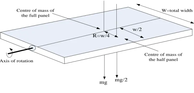
Centre of mass of the full panel
Centre of mass of the half panel
mg/2 mg W=total width w/2 R=w/4 Axis of rotation
Fig -Finding the torque needed to rotate
Mass of the panel m, = 0.8kg
𝑔 = 9.8𝑚𝑠−2 r=w/4=16.5cm/4=4.215cm=.04215m We know, torque ζ=fr =𝑚𝑔𝑟2 = (0.8×9.8×0.0421)/2 =0.165032Nm
Now we need find a suitable stepper motor to supply this amount of power. Therefore we need to calculate the power needed to supply this torque.
Let’s consider a motor of 𝑅𝑃𝑀 = 60
Power, p= (ζ×2π×RPM)/60 watt = (0.165032×2π×60)/60 watt
43
3.5 Calculation of Sunrise and Sunset Time:
Microcontroller will take reading of the local time and date from a digital clock and check for the sunrise and sunset times. Sunrise time in actual solar time (AST) can be calculated from the sunrise angle susing the following,
4
mins
/
deg
720mins
sAST
.Local Standard Time Meridian (LSTM)
The Local Standard Time Meridian (LSTM) is a reference meridian used for a particular time zone and is similar to the Prime Meridian, which is used for Greenwich Mean Time. The LSTM is illustrated below,
The (LSTM) is calculated according to the equation,
Where ΔTGMTis the difference of the Local Time (LT) from Greenwich Mean Time (GMT) in
hours.
Equation of Time (EoT)
The equation of time (EoT) (in minutes) is an empirical equation that corrects for the eccentricity of the Earth's orbit and the Earth's axial tilt.
Where,
44
Figure 18: The time correction EoT is plotted in the figure below.
Time Correction Factor (TC)
The net Time Correction Factor (in minutes) accounts for the variation of the Local Solar Time (LST) within a given time zone due to the longitude variations within the time zone and also incorporates the EoT above.
The factor of 4 minutes comes from the fact that the Earth rotates 1° every 4 minutes.
Local Solar Time (LST)
The Local Solar Time (LST) can be found by using the previous two corrections to adjust the local time (LT).
Hour Angle (HRA)
The Hour Angle converts the local solar time (LST) into the number of degrees which the sun moves across the sky. By definition, the Hour Angle is 0° at solar noon. Since the Earth rotates
45
15° per hour, each hour away from solar noon corresponds to an angular motion of the sun in the sky of 15°. In the morning the hour angle is negative, in the afternoon the hour angle is positive.
Declination
The declination angle has been previously given as,
Where d is the number of days since the start of the year.
Elevation and Azimuth
46
CHAPTER 4
Hardware Implementation
4.1 Introduction
This chapter is dedicated to reflect how we used our research and design to build our prototype of the sun tracking system. After an intensive research on all the available techniques and components, to meet the requirement of the desired suntracking system and to satisfy the prime objective of the project, suitable methods and components were selected and implemented through electrical circuits. In our system we have a control circuitcontrolled by the microcontroller in Arduino. The microcontroller sends signal to the motors polulu mini maestro calculating and comparing time with the help of RTC and the motor rotates the panel.
47
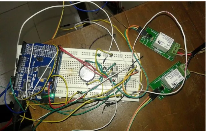
4.2 CONTROL CIRCUIT DIAGRAM
In our proposed system we have implemented our circuit by using one Arduino Mega, three MG995 Servo Motors, two Real Time Clock, one 12v Actuator, two 6v Relay breakout board, one 3v Lithium battery, one Crystal 32.768khz, one Pololu Mini Maestro12 and some male to male and female to male connectors.
Figure 20: The circuitry of our proposed system
Arduino is connected with the PC or laptop via an USB cable. The Arduino gives supply to all the other components used in our circuitry design except the relays and the actuator. Arduino has a fixed 5V power supply which is supplied to the components. The pololu mini maestro12 is connected to Arduino in pin number 10 and 11 via its RxD and TxD pins respectively for transmission and reception of the signals. The real time clock is connected to the Arduino in pin SCL and ground through its pin number 5 and 6. The real time clock gets its power supply from a 3V lithium power supply.
48
Due to interference between the electric field and the magnetic field created by the actuator the circuitry of the actuator is fully separated from the above circuit. The result of this interference causes a huge problem in the whole system. Firstly, the real time clock gets reset; it has a very small power rating so it cannot tolerate the huge power of the actuator which is 12V so it gets reset. Secondly, the other components in the circuit with low power might get burn due to huge power supply. So the power is provided to the actuator externally via a battery.
49
CHAPTER 5
Software Implementation
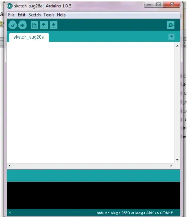
5.1 Software used for programming
In our proposed system we have used Arduino 1.0.3 version for programming. That is an open project that allows writing and debugging codes efficiently which is also immensely supported by vast library files. The library files assisted us in designing algorithms from a sketch books and example’s directory. Verification and compilation of error is smooth and easily accessible. By opening Arduino mega 2560 sketch book we can select specific board and upload programming codes.
50
51
52
53
54
CHAPTER 5
CONCLUSION
The system proposed consists of 3 PV solar panels stacked one above another at some fixed distance to minimize the floor space and fitted with motors controlled by a micro-controller to track the sun to maximize the energy collection. Scheming shows that 18 – 64 % more solar energy can be collected with the proposed system compared with that of conventional single level fixed panel of same size. The proposed system with three panels can be operated in a space of two predictable fixed panel systems and the tracking and sliding mechanisms will make it more efficient than fixed panel system.
The solar powered suntracking system is an energy efficient system in many ways. Firstly, the use of solar energy as the power since it is infinite and renewable. The idea of the sun tracking system is new and the implementation of the system will greatly reduce the electricity problem of our country.
An automated micro-controller based solar tracker system for the three level solar panel system has also been developed that uses a set of equations to calculate the sunrise and sunset times and send signals to the servo-motors to rotate the panels by a fixed angle at pre-determined time intervals. Instead of continuous tracking, the developed system rotates the panels only 11 times a day, in a step of 15˚ in each rotation. As the motors are operated only for a small fraction of the total time the panels collect energy, the energy consumed by the motors will be only a small fraction of the energy collected by the system. Specially designed solar concentrator can be used to further enhance the output of the system. Construction of the proposed system with full micro-controller control is under way.
55 Reference
1. Sarma, MulukutlaS.Electricmachines:steady-state theory and dynamic performance. Secondth Edition
2. Prentice Hal Timothy J. Maloney. Modern Industrial Electronics.Fourth Edition.Prentice Hall.
3. Twidell, J. W. &Weir, A. D.(1986), RenewableEnergyResources, E & F.N. Spon, London
4. Dadamukhamedov S., Muminov, M. N., Tursunov&Khamrit, M.,(1998), Solar Engineering.
5. Zerlaut, G. A.,Solar Tracking Device, USPatent 4.031.384.
6. Gordon. J. M. and Wenger, H. J.,(1991), Solar Energy, pp. 211-217.
7 http://www.c-changes.com/types-of-solar-panel 8. http://energyinformative.org/best-solar-panel-monocrystalline-polycrystalline-thin-film/ 9. http://www.confidencenergy.com/oldvision/news4.html 10. http://www.engineersgarage.com/articles/servo-motor 11. http://www.pololu.com/product/1352 12. https://oceancontrols.com.au/POL-1354.html 13. http://www.pololu.com/docs/0J40/all 14. https://oceancontrols.com.au/POL-1354.html 15 http://en.wikipedia.org/wiki/Arduino 16. http://www.utopiamechanicus.com/article/arduino-versus-arduino-mega-which-to-use/ 17. http://www.quora.com/What-are-the-advantages-of-using-an-Arduino-over-just-using-the-underlying-microcontroller 18. https://learn.adafruit.com/ds1307-real-time-clock-breakout-board-kit/wiring-it-up 19. http://www.maximintegrated.com/en/products/digital/real-time-clocks/DS1307.html
56 20. http://www.adafruit.com/products/264 21. http://www.elprocus.com/rtc-ds1307/ 22. http://www.instructables.com/id/How-to-hack-a-servo-for-continuous-rotation-Towe/step33/Hook-the-servo-up-to-your-microcontroller/ 23. http://en.wikipedia.org/wiki/Linear_actuator