This item was submitted to Loughborough’s Institutional Repository
(
https://dspace.lboro.ac.uk/
) by the author and is made available under the
following Creative Commons Licence conditions.
For the full text of this licence, please go to:
Resource Allocation and Optimization
Techniques in Wireless Relay Networks
by
Juncheng Hu
A doctoral thesis submitted in partial fulfilment of the requirements for the award of the degree of Doctor of Philosophy (PhD), at
Loughborough University.
June 2013
Advanced Signal Processing Group,
School of Electronic, Electrical and Systems Engineering, Loughborough University, Loughborough
Leicestershire, UK, LE11 3TU.
c
CERTIFICATE OF ORIGINALITY
This is to certify that I am responsible for the work submitted in this thesis, that the original work is my own except as specified in acknowledgements or in footnotes, and that neither the thesis nor the original work contained therein has been submitted to this or any other institution for a degree.
... (Signed)
Abstract
Relay techniques have the potential to enhance capacity and coverage of a wireless network. Due to rapidly increasing number of smart phone sub-scribers and high demand for data intensive multimedia applications, the useful radio spectrum is becoming a scarce resource. For this reason, two way relay network and cognitive radio technologies are required for better utilization of radio spectrum. Compared to the conventional one way relay network, both the uplink and the downlink can be served simultaneously using a two way relay network. Hence the effective bandwidth efficiency is considered to be one time slot per transmission. Cognitive networks are wireless networks that consist of different types of users, a primary user (PU, the primary license holder of a spectrum band) and secondary users (SU, cognitive radios that opportunistically access the PU spectrum). The secondary users can access the spectrum of the licensed user provided they do not harmfully affect to the primary user. In this thesis, various resource allocation and optimization techniques have been investigated for wireless relay and cognitive radio networks.
The first contribution, consists of an optimization technique for the use of two way relays to forward signals and perform spatial multiplexing. The problem has been formulated using a Semidefinite Programming (SDP) framework that can be solved using interior point methods. Also, we extend the SDP technique to a two way asynchronous relay network, which utilizes the filter-based relays to overcome inter-symbol interference and enhance the signal to interference-plus-noise ratio (SINR). The simulation results indi-cate that the proposed two-way-relay technique has the ability to enhance the spectrum efficiency and filter-based relays can effectively mitigate the interference and reduce the bit error rate (BER) of signal transmission.
ii
The second contribution is the proposal of a minimum mean square error (MMSE) based design technique for a two way relay network that serves multiple peer-to-peer users. The algorithm aims at minimizing the sum of the mean square errors associated with the retrieval of symbols at multiple destinations subject to a total transmission power constraint at the relays. The problem is solved using a Lagrangian formulation of the constrained optimization problem. Through certain mathematical manipulations of the optimization problem, we suggest a method to choose the optimum Lagrange multiplier that enables full use of the transmission power at the relay.
The third contribution is on a power allocation technique for an orthog-onal frequency division multiplexing (OFDM)-based cognitive radio wireless relay network. In particular, the sum rate maximization problem for the SU network subject to constant total power and interference leakage constraints is considered. This multiple-constraint maximization problem is transformed into an equivalent single constraint problem using two auxiliary variables. Simulation results demonstrate the convergence of the algorithm and the satisfaction of multiple constraints.
Finally the third contribution has been extended to a Multiple-Input Multiple-Output (MIMO)-OFDM based multiple user wireless relay net-work. The aim is to maximize the capacity of the wireless relay network whist satisfying the total transmission power budget.
Statement of Originality
The contributions of this thesis are mainly on the development of various re-source allocation algorithms for two way relay and cognitive radio networks. The novelty of the contributions is supported by the following international journal and conference papers.
In Chapter 4, spatial multiplexing based two relay network that has multiple transmitter-receiver pairs has been proposed. The relaying matrix has been designed using semidefinite programming based optimization for minimising the total transmission power at the relay while satisfying SINR constraints for each user. The original contribution has been supported by the following publications:
1. J. C. Hu, Z. Xiong, Y. Rahulamathavan, K. Cumanan and S. Lambotha-ran, ‘Optimization Techniques for Two-Way Relaying Based Multiuser Multiplexing’ IEEE Eleventh International Workshop on Signal Pro-cessing Advances in Wireless Communications (SPAWC), Marrakech, Morocco, June. 2010, pp. 1-5.
2. J. C. Hu, W. Wang, S. Lambotharan and Z. Xiong ‘Optimization Tech-niques for Asynchronous Two-Way Relaying Based Multiuser Multi-plexing’, IEEE International Conference on Communication Systems (ICCS), Singapore, November. 2010, pp. 545-548.
In Chapter 5, an MMSE based relaying technique for multiple peer-to-peer users has been proposed. An efficient scheme for determining the op-timum Lagrangian multiplier for full use of the transmission power resource has been proposed. This work will be submitted for possible publication in a conference.
3. J. C. Hu and S. Lambotharan, ‘A Cooperative MMSE Strategy for Two-Way Relaying Based Multiuser Multiplexing’, to be submitted.
ii
A power allocation technique for an OFDM-based cognitive radio wireless relay network has been proposed in Chapter 6. The work has been published in:
4. J. C. Hu, S. Lambotharan and X. Zhu, ‘A Power Optimization Tech-nique for an OFDMA-Based Cognitive Radio Relay Network’, IEEE Asia Pacific Wireless Communication Symposium (IEEE APWCS), Singapore, August. 2011.
In Chapter 7, a joint optimization technique for a MIMO relay network with multiple users has been proposed. The scheme is based on singular value decomposition and water filling power allocation for the signals from the source to relay and a set of beamforming for signals from relay to multiple users. The work proposed optimal time sharing for transmissions from source to relay and relay to multiple users, beamforming based spatial multiplexing and power allocation to maximise overall throughput of the network. This work will be submitted to IET Signal Processing.
5. J. C. Hu, J. Tang and S. Lambotharan, ‘Downlink Resource Alloca-tion Techniques for OFDMA-Based Wireless Relay Networks’, to be submitted to IET Signal Processing.
Acknowledgements
I AM DEEPLY INDEBTED to my supervisor Professor Sangarapillai Lam-botharan for his kind interest, generous support and constant advice through-out the past couples of years. I have benefitted tremendously from his rare insight, his ample intuition and his exceptional knowledge. This thesis would never have been written without his tireless and patient mentoring. It is my very great privilege to have been one of his research students. Also, I would like to thank Professor Jonathan Chambers for his support and encourage-ment.
I wish to take this opportunity to thank my father and mother, Xianzhao Hu and Yongqun Zeng, for their moral and financial support throughout my studies. No word can be used to fully express my appreciation and love to them, and I hope my family will be happy every day.
I would like to extend my appreciations to my academic colleagues Mohsen, Cumanan, Rahul, Ranaji, Amod, Jie, Gorgia, Ziming, Yu, Peter, Miao, Gao-jie, Yanfeng, Lulu, Ata, Adel, Mustafa, Salman and so on, for making my stay at Loughborough pleasant. I also wish to acknowledge colleagues in Imago and all friends of my life who gived me support in these amazing six years in UK.
Last, but most importantly, I wish to express my deepest gratitude and love to my beloved girlfriend, Yoyo Zhou, for her endless and selfless love and support. She makes me confident and brave to face and solve every single difficulty in all my life, and I am quite sure that will also be in the future.
Juncheng Hu
List of Acronyms
1G First Generation
2G Second Generation
3G Third Generation
3GPP 3rd Generation Partnership Project
4G Fourth Generation
AF Amplify and Forward
AMPS Advanced Mobile Phone Service AWGN Additive White Gaussian Noise
BC-MAC Broadcast Channel-Multiple-Access Channel
BER Bit Error Rate
BNetzA Bundesnetzagentur
BS Base Station
BPSK Binary Phase Shift Keying
CCI Co-Channel Interference
CDMA Code Division Multiple Access
CF Compress and Forward
List of Acronyms v
CP Cyclic Prefix
CSI Channel State Information
DF Decode and Forward
EDGE Enhanced Data rates for GSM Evolution EV-DO Evolution-Date Optimised
FCC Federal Communications Commission
FDD Frequency Division Duplexing FDMA Frequency Division Multiple Access
FM Frequency Modulation
GP Geometric Programming
GPRS General Packet Radio Service
GSM Global System for Mobile
HC-SDMA High Capacity-Spatial Division Multiple Access
HD High-Definition
IDFT Inverse Discrete Fourier Transform IFFT Inverse Fast Fourier Transform ISI Intersymbol Interference
ISM Industrial, Scientific, and Medical
LTE Long Term Evolution
LTU International Telecommunication Union
List of Acronyms vi
MA Margin Adaptive
M-ary FSK M-ary Frequency Shift Keying M-ary PSK M-ary Frequency Phase Keying
M-ary QAM M-ary Quadrature Amplitude Modulation
MA Margin Adaptive
MIMO Multiple-Input-Multiple-Output MISO Multiple-Input-Single-Output MMR-BS Mobile Multihop Relay-Base Station
MMSE Minimum Mean Square Error
MS Mobile Station
MU Mobile User
NMT Nordic Mobile Telephony
NRT Non-Realtime
Ofcom Office of Communications
OFDM Orthogonal Frequency Division Multiplexing OFDMA Orthogonal Frequency Division Multiple Access
PU Primary User
PUSC Partial Usage of Subcarriers
QoS Quality-of-Service
QPSK Quadrature Phase Shift Keying
List of Acronyms vii
RF Radio-Frequency
RKRL Radio Knowledge Representation Language
RS Relay Station
SC-FDMA Single-Carrier Frequency Division Multiple Access SDMA Space Division Multiple Access
SDP Semi Definite Programming
SIMO Single-Input-Multiple-Output
SINR Signal-to-Noise-plus-Interference Ratio SISO Single-Input-Single-Output
SMS Short Message Service
SU Secondary User
SVD Singular Value Decomposition TACS Total Access Communication System TDMA Time Division Multiple Access
TDD Time Division Duplex
TD-SCDMA Time Division-Synchronous Code Division Multiple Access
TWRN TwoWay Relay Network
UMTS Universal Mobile Telecommunications System
UT User Terminal
WCDMA Wideband Code Division Multiple Access
List of Acronyms viii
WLAN Wireless Local Area Network
WLS Weighted Least Square
WMAN Wireless Metropolitan Area Network WPAN Wireless Personal Area Network WRAN Wireless Regional Area Network
List of Symbols
Scalar variables are denoted by plain lower-case letters, (i.e., x), vectors by bold-face lower-case letters, (i.e., x), and matrices by upper-case bold-face letters, (i.e., X). Some frequently used notations are as follows:
E{·} Statistical expectation (·)T Transpose (·)H Hermitian transpose (·)∗ Complex conjugate (·)(q) qth iteration ∥.∥1 L1 norm ∥.∥2 Euclidean norm (.)−1 Matrix inverse Re{·} Real part Im{·} Imaginary part Tr{·} Trace operator I Identity matrix dom Domain
diag(x) Diagonal matrix with vector x
List of Figures
1.1 The mobile spectrum in Europe [1]. 6
2.1 Comparison of spectrum efficiency between conventional FDM
and OFDM. 15
2.2 OFDM signal consisting of several narrow sub-carriers. 16
2.3 OFDM subcarrier in the time domain. 16
2.4 The equivalent frequency domain subcarrier representation of
Fig. 2.3 17
2.5 An OFDM symbol and cyclic prefix. 17
2.6 The beamforming techniques. 22
2.7 The receiver beamformer design. 24
2.8 A MIMO system with Mt transmit antennas and Mr receive
antennas.. 29
2.9 Transmit precoding and receiver shaping. 30
2.10 Parallel decomposition of the MIMO channel. 31
2.11 MIMO-OFDM system 32
2.12 Three-node relay network and cooperative relaying. 34
2.13 One way relay network 35
2.14 Two way relay network 38
LIST OF FIGURES xi
2.15 Spectrum hole. 42
2.16 Interweave spectrum scheme. Green and red represent the spectrum occupied by the primary users and secondary users
respectively. 43
2.17 Underlay spectrum paradigm. Green and red represent the spectrum occupied by the primary users and the secondary
users respectively. 44
4.1 A relay network of M pairs of nodes and N relay nodes. 63 4.2 Relay average total power versus SINR targets. 71 4.3 The outage probability (infeasible problem) versus number of
relays. 72
4.4 A relay network consisting ofM pairs of source nodes and R
relay nodes. 73
4.5 Relay average total power and the outage probability against
SINR targets. 80
4.6 The BER comparison between the proposed relay network and AWGN channel for various values of SINR targets. 80
5.1 A relay network of M pairs of nodes and N relay nodes. 84 5.2 Comparison of the BER performance for the two-way relay
network with one source and one destination for various
num-bers of relays. 91
5.3 Comparison of the BER performance for the two-way relay network with six relays for various numbers of source and
destination pairs. 92
LIST OF FIGURES xii
6.2 The total capacity against total interference threshold. 102
6.3 The total capacity versus total power. 103
6.4 Convergence of the auxiliary variablesα and β. 103
7.1 A relay network with an Nt-antenna BS, an Nr-antenna RS
andRusers with one antenna for each. The channel gains are
shown for the mth subcarrier. 107
7.2 Comparison of the optimal achievable sum rates for 16 subcar-riers obtained by serving 3 users and 1 user in each subcarrier. 128 7.3 Comparison of the optimal achievable sum rates for 16
sub-carriers obtained by using beamforming for different users in
List of Tables
4.1 Table of outage probabilities (O.P.) for varying SINRs. The outage probability represents the probability that the target
SINRs can not be achieved. 70
7.1 Proposed algorithm for beamforming vector using BC-MAC
du-ality. 116
7.2 Proposed algorithm for Lagrangian multipliers using bisection
method. 122
Chapter 1
INTRODUCTION
1.1 Evolution of Wireless Communication Systems
Wireless communication has become one of the most irreplaceable areas in the communication field today, and it has been advancing at an incredible speed over the last decades. Wireless local area network (WLAN) is one of the most important and successful wireless communication applications, and because of the high-speed data transmission and simplicity of installation, it has become very popular in the home, university and commercial districts offering wireless access to customers.
The federal communications commission (FCC) authorized the public use of the Industrial, Scientific, and Medical (ISM) frequency bands for wireless LAN products to enable the commercial development of wireless LANs in 1985. The ISM bands are all unlicensed, and located at 900 MHz, 2.4 GHz and 5.8 GHz, and the Unlicensed National Information Infrastructure (U-NII) band at 5 GHz. Due to the unlicensed spectrum, different systems can operate in these bands; however, they must tolerate any interference from other ISM equipments. And for the same reason, the ISM band is also very absorbing to wireless LAN users.
Institute of Electrical and Electronic Engineering (IEEE) 802.11 is a set of standard to realize WLAN communication, in which the 802.11a and 802.11b protocols define the most popular original standard in order to sat-isfy the requirement of high data rate on limited channel bandwidth. Build-1
Section 1.1. Evolution of Wireless Communication Systems 2
ing upon previous 802.11 standards, new standards are evolved to meet different demand. For example, 802.11e is a wireless standard that supports LAN by defining the Quality of Service (QoS), and it is an enhancement to the 802.11a and 802.11b WLAN specifications; Input Multiple-Output (MIMO) has been included in the 802.11n standards, which support for wider channels and beamforming abilities to achieve higher data through-put. Thanks for the help of these standards, WLAN is being used widely with low cost and easy fast access.
The mobile communication develops and evolves rapidly. The first gen-eration (1G) of wireless data modems was exploited in the early 1980’s by amateur communication groups, which was based on the analogue system. It works within the 26 MHz spectrum of the 900 MHz ISM band employ-ing direct sequence spread spectrum and the data rate is approximately 1-2 Mbps, therefore, the focus is on the service of voice information. Advanced Mobile Phone System (AMPS), Nordic Mobile Telephone (NMT), and Total Access Communication System (TACS) are mobile phone system standards based on analog technology in the first generation (1G).
The second generation (2G) telecommunication networks were commer-cially launched in the early 1990s in Europe. They can be divided into Time Division Multiple Access (TDMA)-based and Code Division Multiple Access (CDMA)-based techniques. TDMA divide transmission of signals to various users into time slots and CDMA allocates each user a special code to communicate over a multiplex physical channel. 2G was launched on the Global System for Mobile communications (GSM) standard. GSM uses digital modulation for improved audio quality and offers the customers with voice and limited data services, such as Short Message Service (SMS). This also brought significant benefit to users as digital technology requires substantially low battery power consumption and yields unprecedented im-provement in the quality of services. After that, 2.5G was introduced by
Section 1.1. Evolution of Wireless Communication Systems 3
applying General Packet Radio Service (GPRS). It provides moderate-speed data transfer, by using unused TDMA channels in, for example, the GSM system. GPRS was able to send and receive data at the speed of 56 - 115 kbps.
The third generation (3G) mobile telecommunications technology pro-vides even much better performance. Thanks for the result of ground-breaking research and development carried out by the International Telecom-munication Union (ITU), 3G technology is still used nowadays. Different countries employ different 3G standards such as Wideband Code Division Multiple Access (WCDMA), Time Division-Synchronous Code Division Mul-tiple Access (TD-SCDMA), Worldwide Interoperability for Microwave Ac-cess (WiMAX) and CDMA2000 including CDMA2000 1x, CDMA2000 3x, CDMA2000 Date Optimised (EV-DO) and CDMA2000 Evolution-Date/Voice (EV-DV). 3G provides an information transfer rate of at least 200 kbit/s, and because of that, it can support the service of wireless voice telephony, mobile internet access, fixed wireless internet access, video calls and mobile TV. However, 3G performance may not be sufficient to meet needs of emerging high performance services like multi-media, full motion video and teleconferecencing, which appeals a new generation of technologies with higher performance.
As a successor of 3G standards, the fourth generation (4G) of mobile telecommunications technology has been researched and applied. 4G tech-nologies include the 802.16e mobile WiMax, High Capacity-Spatial Division Multiple Access (HC-SDMA), and Long Term Evolution (LTE). It provides much higher data rate and streaming media, ranging from the Ethernet-grade 100Mbps between any two points in the world to 1Gbps, if the cus-tomers are in comparatively fixed positions. Otherwise, much wider band-width, coverage and range can be increased with a lower cost. Due to good QoS, people can enjoy the high-quality media services like gaming services,
Section 1.2. Development of Wireless Techniques 4
high-definition (HD) mobile TV, video conferencing, 3D television, and many more.
In 4G, transmission techniques such as MIMO, OFDM and Orthogonal Frequency Division Multiple Access (OFDMA) are the key features, which is also the focus of this thesis. MIMO uses multiple antennas at both the trans-mitter and the receiver to realize the spatial diversity gain and to increase the reliability of the wireless link. MIMO is an important part of modern wireless communication standards such as IEEE 802.11n (Wi-Fi), 3rd Gen-eration Partnership Project (3GPP), Long Term Evolution and WiMAX. On the other hand, OFDM technique splits the radio spectrum into multiple smaller narrowband channels enabling simultaneous transmission of multiple streams of data to users. OFDMA is a form of OFDM for user multiplexing. These technologies within the context of relay networks are investigated in this thesis.
1.2 Development of Wireless Techniques
The use of relay in wireless network improves the performance such as the throughput, data rate and coverage. Relay techniques have been treated as one of the most important standardization process for the next-generation (4G) mobile broadcast communication systems. These communication sys-tems include the 3GPP LTE-Advanced [2], IEEE 802.16j, and IEEE 802.16m. Different global standards of WiMAX adopt relay communication, es-pecially the first-mile/last-mile broadband wireless access in big cities, and backhaul services for voice/data communication. WiMAX has become one of the 3G standards in 2007, and the relay-based multihop technique has been developed by the 802.16j working group.
There are three possible relay schemes, namely amplify and forward (AF) [3, 4], decode and forward (DF) [5, 6], and compress and forward (CF) [7, 8]
Section 1.2. Development of Wireless Techniques 5
strategies.
In the AF scheme (analog repeaters) the symbols are amplified and re-transmitted by the relay nodes. In this scheme, the relay link fading and ad-ditive receiver noise could deteriorate the received signal. In the DF scheme (digital repeaters or layer 2 relays) the received signal is demodulated and decoded by the relay before retransmission. In this situation, the additional degradation is not contained in the forwarded signal, but only symbol er-rors resulting from it. The CF strategy allows the relay station to compress the received signal from the source node and forwards it to the destination without decoding the signal.
Relays can be also consist of multiple antennas providing spatial diversity for transmission and reception. The advantages of relay networks can be summarized as follows:
1.) Extension of coverage: Relay network supports the wireless com-munications in relatively complex terrains and buildings. Base stations in subway or areas under shadow of big buildings may employ relay nodes to assist transmission.
2.) Improvement in the capacity: Relay network provides more than one paths for communicating the symbols. The purpose is to transmit the same data at the same time, thorough relays which could provide spatial diversity increasing the system capacity.
3.) Reduction of transmit power: With the increasing number of users, base station cannot transmit signal effectively to each destination because it will require very high power to ensure QoS to overcome the attenuation in the transmission channel. The excessive power will introduce undue interference in the network. Relay nodes can help BS to disperse most of the transmit power, which will improve the capacity indirectly and enhance frequency re-usage.
Section 1.3. Motivation for Cognitive Radio Techniques 6
the cost of relay deployment is relatively low. Hence, the coverage can be enhanced without significant additional investment.
1.3 Motivation for Cognitive Radio Techniques
The spectrum is considered as one of the most important optimization pa-rameters in wireless networks. Fig.1.1 shows the distribution of spectrum occupancy in Europe. These bands are filling up very fast, and most of these radio spectrums have already been licensed. As seen, the spectrum region between 5150 MHz and 5350 MHz, as well as that between 5470 MHz to 5850 MHz can be used for WLAN. It can be seen that in the same region of spectrum for WLAN, there are two other network services appear and share the frequencies. The most of the spectrum bands have been licensed, and the unlicensed ones will also be filled up soon resulting in spectrum scarcity.
Figure 1.1. The mobile spectrum in Europe [1].
The government agencies restraint the right of licensing spectrum re-sources who implement a nation’s rights in spectrum usage, for example, by the U.K. Office of Communications (Ofcom), by the FCC of the United States, or by Germany’s Bundesnetzagentur (BNetzA), and the others. This
Section 1.3. Motivation for Cognitive Radio Techniques 7
conservative approach of licensing spectrum exclusively for different opera-tors and services is inefficient. It is reflected in a recent survey of spectrum utilization made by the FCC [17], which shows that, for example, maximum total spectrum occupancy is only 13.1% from 30 MHz to 3 GHz in the spec-trum measurement taken in New York City. The same situation appears in the most crowded area of downtown Washington, D.C.. The occupancy of frequency bands is less than 35% of the radio spectrum below 3 GHz. Ways of enhancing the spectrum utilization is a very hot research topic, in particular within the context that the spectrum usage varies continually in time, frequency and geographic locations.
Cognitive radio is considered as one of the most effective techniques to improve the electromagnetic radio spectrum utilization [9–12]. The idea of “cognitive radio” was first offered by Joseph Mitola in a seminar at KTH in 1998 [13], which was later published in 1999. Mitola presented it based on a new language called the Radio Knowledge Representation Language (RKRL). A cognitive radio could develop the flexibility of personal wireless services.
Cognitive radios have the ability to sense radio spectrum for spectrum holes and transmit signals through the spectrum that is not occupied. The definition of “spectrum hole” can be presented as [14]:“A spectrum hole is a band of frequencies assigned to the primary user, but, at a particular time and specific geographic location, the band is not being utilized by that user”. Spectrum utilization can be enhanced significantly if the secondary user (who is not been serviced) can employ the “spectrum hole” which has been made vacant by the primary user at the right location and the time in question. Cognitive radio, inclusive of software-defined radio, has been projected as the means to encourage the efficient use of the spectrum by exploiting the existence of spectrum holes. Other possible arrangement in cognitive radio is to enable the SUs to use the spectrum provided the interference due to SU
Section 1.4. Thesis Outline 8
transmissions do not harmfully affect the PU receivers. This arrangement is considered as part of the relay technique proposed in the thesis.
1.4 Thesis Outline
Spatial multiplexing techniques and adaptive resource allocation techniques significantly enhance the spectrum utilization. The techniques developed for conventional wireless networks cannot be directly applied to a cognitive radio relay network due to the additional interference constraints on the primary users. Hence the work in this thesis mainly focuses on performing spatial multiplexing using two way relay network and the resource allocation tech-niques for cognitive radio networks using various mathematical optimization techniques.
The Chapter 2 provides a survey on various resource allocation tech-niques used in conventional wireless networks. Initially, multi-carrier mod-ulation technique, which is the basis of OFDM and OFDMA techniques is discussed. Following on from this, static and adaptive resource allocation techniques for wireless networks are described. Multiple antenna techniques such as beamforming and spatial multiplexing are also discussed briefly. Fi-nally, relay network is introduced and cognitive radio techniques are sur-veyed.
The Chapter 3 briefly introduces the fundamentals of convex optimiza-tions, including definition of convex funcoptimiza-tions, convex sets problems. These are the basis of the resource allocation techniques developed in this thesis. The novel contributions in this thesis are covered in Chapters 4, 5, 6 and 7 as described below.
Section 1.4. Thesis Outline 9
Contribution Chapters
In Chapter 4, we have used two way relays to perform spatial multiplex-ing for multiple transmitter-receiver pairs usmultiplex-ing a semidefinite programmmultiplex-ing (SDP) technique. The SDP formulation considered has the advantage of using minimum possible transmission power while ensuring desired Signal to Interference-plus-Noise Ratio (SINR) for each user is attained. The SDP technique is extended to a two way asynchronous relay network, which uti-lizes the filter-based relays to overcome inter-symbol interference. The sim-ulation results indicate that the proposed two-way-relay technique enhances the spectrum efficiency and filter-based relays can effectively mitigate the interference from the various users and decrease the BER. In Chapter 5, we extend our earlier work on MMSE-based precoder design [15] to a two way cooperative relay network. Single and multiple pairs of source and des-tination are considered to demonstrate the potential of the two-way relay networks for forwarding signals while performing spatial multiplexing. We propose a new approach to determine the optimum signal scaling factor re-quired to use all available transmission power at the relay though certain manipulation in the Lagrangian formulation.
The focus of Chapter 6 is on a new resource allocation technique to a cognitive radio wireless relay network consisting of transmissions from the base station to a relay station and from the relay station to multiple destinations. This optimization problem has both the sum power constraint and the interference leakage constraint and is solved by combining multiple constraints into a single constraint using auxiliary variables and by adapting the auxiliary variables using a sub-gradient method.
In Chapter 7, a joint beamforming and power allocation technique to maximize the total capacity of the whole network has been proposed. In the MIMO transmission between BS and RS, Singular Value Decomposition
Section 1.4. Thesis Outline 10
(SVD) is utilized to design the transmit and receive beamforming vectors and the power allocation is performed using waterfilling algorithm. In the MISO transmission between RS and multiple-users with single antenna, transmit beamforming vectors are designed using BC-MAC duality. The waterfilling based power allocation at BS and the user power allocation at the RS needs to be jointly optimized so that the sum rate of users should match the back-haul BS-RS data throughput. We solved this problem using the Lagrangian optimization.
Finally, conclusions are drawn in Chapter 8 together with a discussion on possible future directions.
Chapter 2
RESOURCE ALLOCATION
TECHNIQUES FOR
WIRELESS
COMMUNICATION
NETWORKS
2.1 IntroductionThe exponential growth of wireless communication systems has opened up new challenges in the way in which communication network should be de-signed and optimized. For wireless communication systems, one of the major challenges is the increasing demand for spectral resources created by high data rate services such as rich multimedia and interactive services. Vari-ous resource allocation techniques have been proposed to utilize the scarce resources efficiently [10,16–20]. These techniques involve strategies and algo-rithms for controlling transmission power, frequency allocation, modulation scheme and channel coding. The main objective of the resource allocation scheme is to make the best use of the scarce radio resources to increase spectrum efficiency as much as possible [21].
Section 2.1. Introduction 12
In this chapter, carrier modulation techniques as well as multi-antenna techniques for general wireless communication system are intro-duced. First OFDM technique is discussed, followed by beamforming tech-niques, including receiver beamforming and transmitter beamforming. Spa-tial multiplexing techniques can also improve the system performance against fading. The MIMO OFDM is also studied. After that, the relay networks are introduced, specifically two way relay network and cooperative relay network are discussed in details. Finally, the concept cognitive radio is produced for high spectrum efficiency.
Multi-carrier modulation technique is an attractive solution for providing higher data throughput on limited bandwidth channels. The basic idea of multi-carrier modulation is to divide the transmitted signal into many differ-ent substreams, send over many differdiffer-ent subchannels [16, 18, 22, 23]. Typ-ically the subchannels are orthogonal under ideal propagation conditions. The frequency selective wide band channel is converted into frequency non-selective multiple subchannels, meaning the data stream modulated on each sub-band is facing narrowband thus improving the system’s performance.
Beamforming is a signal processing technique for directional signal trans-mission and reception. By combining elements in a phased array, the sig-nals at a particular angle experience constructive interference while others experience destructive interference. Beamforming takes advantage of inter-ference to change the directionality of the array thus improves the system’s performance [16, 24–26]. Spatial multiplexing technique is a transmission technique in MIMO wireless communications to transmit and receive signal using multiple antennas. The technique supports enhanced data throughput even under conditions of interference, signal fading, and multipaths [27, 28]. Relay transmission can enhance the reliability, increase the rate and save the transmission power in a wireless network. There has been many works on relay networks [15,24,26,29–43]. Two Way Relay Network (TWRN) has been
Section 2.2. Multi-Carrier Modulation Techniques 13
considered as a good way of saving the spectrum in the communications as it significantly reduces the spectral loss caused by the half-duplex constraint in practical systems.
Cognitive radio is a form of wireless communications in which the avail-ability of communication channels can be intelligently detected. This opti-mizes the use of available radio-frequency (RF) spectrum while minimizing interference to other users. White space has been introduced as an impor-tant aspect of cognitive radio in which the unused spectrum in the television frequencies are utilized [44, 45].
2.2 Multi-Carrier Modulation Techniques
Multi-carrier modulation is a technique for data-transmission by dividing a high-bit rate data stream into several parallel low bit-rate data streams and using these low bit-rate data streams to modulate several carriers. The basic idea of multi-carrier modulation is to divide the whole channel bandwidth into a number of smaller frequency bands. The number of substreams is chosen to make the symbol time on each substream much greater than the delay spread of the channel or, equivalently, to make the substream band-width less than the channel coherence bandband-width. This ensures that the substreams will not experience significant intersymbol interference (ISI).
Consider a linearly-modulated system with data rate R and passband bandwidth B. The signal experiences frequency-selective fading, if the co-herence bandwidth for the channel is assumed to be Bc < B. The basic
premise of multicarrier modulation is to break this wideband system into N linearly-modulated subsystems in parallel, each with subchannel band-width BN = B/N and data rate RN ≈ R/N. For N sufficiently large, the
subchannel bandwidthBN =B/N << Bc, which ensures relatively flat
Section 2.2. Multi-Carrier Modulation Techniques 14
time TN of the modulated signal in each subchannel is proportional to the
subchannel bandwidth 1/BN. So BN << Bc implies that TN ≈ 1/BN >>
1/Bc ≈Tm, where Tm denotes the delay spread of the channel. Thus, if N
is sufficiently large, the symbol time is much bigger than the delay spread, so each subchannel does not experience any ISI degradation.
There are lots of useful properties such as delay-spread tolerance and spectrum efficiency in carrier modulation technique. OFDM is a multi-carrier modulation technique with densely spaced submulti-carriers, that has gained a lot of popularity among the broadband community in the last few years.
2.2.1 Introduction to OFDM
OFDM is a multi-channel modulation scheme employing Frequency Divi-sion Multiplexing (FDM) of orthogonal subcarriers, each modulating a low bit-rate digital stream, maintaining total data rates similar to conventional single-carrier modulation schemes in the same bandwidth. Compared to FDM, which divides the bandwidth into N non-overlapping frequency sub-channels, OFDM divides the bandwidth intoN overlapping (but orthogonal) subcarriers using an Inverse Fast Fourier Transform (IFFT) block instead, which can overcome the problem of bandwidth wastage (the value ofN is a power of 2). As seen in Fig 2.1, OFDM can save the bandwidth as compared to FDM. This ensures that the carriers are spaced at the Nyquist minimum, which in turn maximizes the bandwidth efficiency. The orthogonality of OFDM comes from the precise relationship between the subcarriers that make up one OFDM symbol. In an OFDM system, each subcarrier has ex-actly an integer number of cycles in a givenT time interval. In other words, the number of cycles between any two adjacent subcarriers differs exactly by one. This implies that each subcarrier frequency is an integer multiple of a base frequency (that is, f1 = f0, f2 = 2∗f0, f3 = 3∗f0, and so on). These properties allow each subcarrier to be individually and independently
Section 2.2. Multi-Carrier Modulation Techniques 15
Figure 2.1. Comparison of spectrum efficiency between conventional FDM and OFDM.
demodulated from any other adjacent subcarriers. Orthogonality between each subcarrier is satisfied by
∫ T 0 ej2πfmte−j2πfntf(t)dt= 0, m̸=n T, m=n, (2.2.1)
In order to maintain orthogonality in an OFDM system, we have to make sure that
1 Ts
= ∆f (2.2.2)
where ∆f is the sub-carrier spacing and Ts is the symbol duration, as seen
in Fig. 2.2.
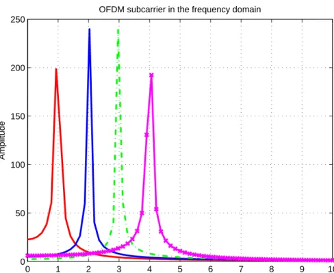
IfN-point Inverse Discrete Fourier Transform (IDFT) (or FFT) is used, the total bandwidth (in Hz) isW =N∆f. An equivalent frequency domain representation of Fig. 2.3 can be seen in Fig 2.4, in which we assume that it is a 512-point FFT, the frequency of different signals f1 = f0 = 1Hz, f2 = 2∗f0 = 2Hz, f3 = 3∗f0 = 3Hz, f4 = 4∗f0 = 4Hz, respectively, and the sampling frequency fs = 80Hz. Later an extended symbol period
is introduced which adds the duration of Cyclic Prefix (CP)Tcp into symbol
Section 2.2. Multi-Carrier Modulation Techniques 16
Figure 2.2. OFDM signal consisting of several narrow sub-carriers.
0 0.1 0.2 0.3 0.4 0.5 0.6 0.7 0.8 0.9 1 −1 −0.8 −0.6 −0.4 −0.2 0 0.2 0.4 0.6 0.8 1 Time (s) Amplitude
OFDM subcarrier in time domain
1st subcarrier 2nd subcarrier 3rd subcarrier 4th subcarrier
Figure 2.3. OFDM subcarrier in the time domain.
2.2.2 The Cyclic Prefix
The robustness against delay spread is one of the main advantages of OFDM over a single-carrier system. Channel delay spread causes ISI which causes irreducible error floor, hence limiting the maximum data rate. Since symbol
Section 2.2. Multi-Carrier Modulation Techniques 17 0 1 2 3 4 5 6 7 8 9 10 0 50 100 150 200 250 Frequence(Hz) Amplitude
OFDM subcarrier in the frequency domain
Figure 2.4. The equivalent frequency domain subcarrier representa-tion of Fig. 2.3
duration of each subcarrier in OFDM isN times longer than that of a single carrier system, OFDM is more robust to delay spread. However, OFDM could still suffer from ISI. CP can be used to avoid ISI. The use of CP allows to represent the linear convolution of the channel impulse response in terms of cyclic convolution. The length of CP is equal to or longer than maximum channel delay spread. The extended OFDM symbol is showen in Fig. 2.5.
Section 2.2. Multi-Carrier Modulation Techniques 18
2.2.3 Matrix Representation of OFDM
In order to explain how the CP in OFDM can help to eliminate ISI, a matrix representation is produced. We assume that the input symbols {sk(i)}Ni=1 denote the transmit symbols for thekthOFDM block. N denotes the number of OFDM subcarriers (the number of constellation symbols to be transmitted in one OFDM block). An N-point IFFT is taken to get {xk(i)}Ni=1 after serial to parallel conversion of the input symbol stream. We add a cyclic redundancy of length ν (the number of CP samples) as a prefix in such a way thatx(k)(−i) =x(k)(N−i) fori= 1,2, . . . , ν in front of the first symbol xk(0).
The signal is then transmitted on a multipath channel with the Channel Impulse Response (CIR) of the multipath channel of length L denoted by the vector as
h= [h0 h1 · · · hL]T ∈CL×1.
The kth channel output symbol
yk= [
y0k y1k · · · yNk−1 ]T
∈CN×1
can be expressed using matrix notation in terms of the transmitted samples xk(i) and noise vector ηk∈CN×1 as,
Section 2.2. Multi-Carrier Modulation Techniques 19
where E = L−ν −1 is the channel length exceeding the duration of CP ν. We can see that the entities marked in red color appear only if CIR length L exceeds the duration of CP, i.e. E >0 and thereby contribute to what is called ISI.
For the reason stated above, we consider the CP length to be greater than CIR length, and with incorporation of CP property xk(−i) =xk(N −i) for
i= 1,2, . . . , ν, thekth channel output symbol can be expressed as
As can be seen, by using long enough CP, the linear convolution of the channel impulse response and the signal becomes cyclic convolution, and the previous symbols will not affect the current one any more and ISI has been eliminated. Since any IDFT and DFT matrix can diagonalize a circulant matrix, IDFT at the transmitter and DFT at the receiver can diagonalize the channel yielding orthogonal subcarrier for OFDM transmission.
2.2.4 Overview of OFDMA
Earlier OFDM has been used as a modulation scheme for wireless systems, where all the subchannels of OFDM are assigned to a single user at any given time (i.e., IEEE 802.11a/g). Later TDMA or FDMA has been used with OFDM in order to support multiple users. This kind of static re-source allocation cannot provide a good performance. Disadvantage of this static resource allocation is that multi-user diversity is not exploited (i.e.,
Section 2.2. Multi-Carrier Modulation Techniques 20
different users have different channel gains on same subchannel). OFDMA has been developed to exploit the multi-user diversity where multiple users are allowed to transmit simultaneously on different subchannels per OFDM symbol. The probability that all users experience worst channel gain in a particular subchannel is typically quite low. Hence, adaptive resource alloca-tion algorithms can be developed to efficiently allocate resources to multiple users by exploiting the multi user diversity.
2.2.5 Resource allocation techniques
Adaptive resource allocation techniques allocate radio resources to various users according to users channel gain and QoS requirements. The prob-lem of assigning the subchannels and transmission power to different users in an OFDMA system has been intensively studied over the past decade (i.e., [46–51] and references therein). All of these studies can be divided into two categories namely Margin Adaptive (MA) and Rate Adaptive (RA) resource allocation problems [46–48]. The objective of the MA problem is to minimize the total transmission power subject to users’ individual data rate constraint BER requirements. The objective of the RA is to maximize system data throughput subject to a total transmission power constraint. Various resource allocation techniques available for OFDMA can also be used in cognitive radio networks to allocate radio resources to secondary users while maintaining the interference leakage to the primary user below a threshold. Various work proposed for cognitive radio networks based on OFDMA technique and/or multiple antennas technique are reviewed as fol-lows.
The OFDMA has been considered as one of the powerful techniques for cognitive radio network due to its natural ability to use different por-tions of the spectrum. The work in [20, 52] introduced the resource alloca-tion technique used in OFDMA-based cognitive radio networks. The work
Section 2.2. Multi-Carrier Modulation Techniques 21
in [52] proposed an adaptive radio resource allocation algorithm for a MIMO OFDMA based uplink cognitive radio network with multiple secondary users (SUs) and multiple primary users (PUs). The aim is to admit as many SUs as possible in various subcarriers while ensuring interference is not leaked to PUs. In [20], resource allocation problem has been considered for a mul-tiuser OFDM-based cognitive radio system under a non-realtime (NRT) user scheme. In this work, the user data rates have been maintained propor-tionally while at the same time providing an improved system throughput. In [53], power is allocated to each subchannel, by considering the received interference as a fairness metric which has been solved using Lagrangian dual function. Due to high computational complexity of determining optimal so-lution for OFDMA based resource allocation problem, some low complexity algorithms were proposed in [18, 54]. The work in [18, 54] considered a sin-gle user cognitive radio network and maximized the cognitive radio network throughput by allocating data bits to various subchannels, optimally.
The work in [55], presents a systematic method of distributed algorithms for power control based on geometric-programming, which forms important resource allocation technique for beamforming in chapter 7. Asymmetric resource allocations for the temporal power in different time slots have been proposed in the works of [56] and [43], respectively. In these works, La-grangian optimization and the “waterfilling” algorithm are utilized to de-termine power allocations in different subchannels for OFDMA. These are basis for the techniques proposed in chapters 6 and 7.
In this thesis, resource allocation for wireless network based on beam-forming technique and spatial multiplexing technique is considered. Hence, a brief description about beamforming technique, spatial multiplexing tech-nique and resource allocation based on both these techtech-niques are provided in the following sections.
Section 2.3. Beamforming Techniques 22
2.3 Beamforming Techniques
Applications of beamforming can be found in many disciplines including radars, sonars, and communications. It can be considered as a marriage between antenna technology and digital technology. In communication sys-tems, the duty of an antenna is to receive or transmit electromagnetic waves. For beamforming, as can be seen in Fig. 2.6, there are several antennas be-side each other.
Figure 2.6. The beamforming techniques.
Each antenna on its own is omni directional. By applying phase shifts on the signals of each antenna and summing the results, a beam pattern can be produced as a response to the total array of antennas. By changing the phase or time delay of the signals the beam pattern can be steered toward different directions and this is called beamforming. Beamforming is a signal processing technique used in the physical layer of a communication network to control the directionality of transmission or reception of a signal using antenna array at the transmission or at the reception [57]. Beamforming has many benefits:
1. Higher SNR: The highly directional transmission improves the link budget. This can be used to increase coverage.
ex-Section 2.3. Beamforming Techniques 23
ternal and internal co-channel interference (CCI) by exploiting the spatial properties of the antennas. Since the interference comes from a certain di-rection, the beamformer can be applied to place nulls towards interference.
3. Higher network efficiency: By significantly reducing the CCI, beam-forming can allow much denser deployments than single antenna systems. Due to higher link budget, the likelihood of running high-order modulations (64QAM, 16QAM) is much higher even at the edges of the cell. Overall capacity is greatly improved.
The structure of beamforming for reception and transmission of signals has been introduced as follow:
2.3.1 Receiver Beamforming Techniques
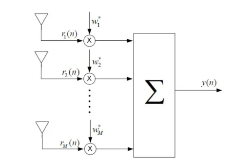
In receiver side beamforming, multiple antennas are deployed at the receiver. When only one antenna is used at the transmitter, this scheme is referred to as Single-Input-Multiple-Output (SIMO) in literature. In the receiver beamforming design, the objective is to estimate the desired signal in the presence of noise and interference. Fig. 2.7 depicts a receiver beamformer structure. The output of the beamformer can be written as
y(n) =wHr(n), (2.3.1)
wherenis the time index, r(n) = [r1(n) · · · rM(n)]T is theM×1 received
signal vector and w = [w1 · · · wM]T is the complex beamforming weight
vector. The received signal vector is given by
r(n) =d(n) +i(n) +η(n), (2.3.2)
where d(n), i(n) and η(n) are the desired signal, interference and receiver noise respectively. Hence, the received signal-to-noise-plus-interference ratio
Section 2.3. Beamforming Techniques 24
Figure 2.7. The receiver beamformer design.
(SINR) at the receiver can be given as follows [58]:
SINR = w HR dw wHR i+nw , (2.3.3) where Rd = E { d(n)d(n)H} and Ri+n = E { [i(n) +η(n)] [i(n) +η(n)]H }
are the signal and interference-plus-noise covariance matrices. The optimum beamforming weight vector that maximizes the SINR of received signal can be obtained as a generalized eigenvalue solution as follows [28]
R−i+1nRdw=λmaxw, (2.3.4)
whereλmax is the maximum eigenvalue of the matrixR−i+1nRd.
Proof: See Appendix A.
Hence, the optimal beamformer weight vector is equivalent to generalized eigenvector of the matrices [Rd, Ri+n] [28].
Section 2.3. Beamforming Techniques 25
2.3.2 Transmitter Beamforming Techniques
For the transmit beamforming multiple antennas are deployed at the trans-mitter. When the receiver employs only a single antenna, the scheme is also known as Multiple-Input-Single-Output (MISO) system. Beamforming at the transmitter is substantially different in several aspects as compared to a beamformer at the receiver. In the latter, the design will only deter-mine the performance of a specific user whereas the transmit beamformer will affect not only the desired user but also all the users in the coverage area. Hence, the transmit beamforming design should ideally take into con-sideration the system level performance, i.e., all the users in the reception area rather than a specific set of users. Another fundamental difference is the channel knowledge. For receiver beamformer design, the receiver could estimate the channel coefficients using the training signal. For transmitter beamformer design, the channel knowledge could be made available to the transmitter by sending the estimates of the Channel State Information (CSI) from the receiver through a finite rate feedback channel [59–61] .
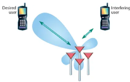
The transmitter beamforming can be used to enhance SINR of a particu-lar user in the network. However, by steering multiple beams, multiple users can access the same frequency band simultaneously. This is known as spatial multiplexing. The focus of this section is on multiuser spatial multiplexing. The transmit beamformers can be designed to satisfy QoS requirements for each user i.e., received SINR for each user. Consider a wireless network base station equipped with Nt transmit antennas serving K users. Each user is
equipped with a single antenna. The signal transmitted by the base station is given by
x(n) =Ws(n), (2.3.5)
where s(n) = [s1(n)· · ·sK(n)]T, sk(n) (k = 1,2,· · · , K) is the symbol
Section 2.3. Beamforming Techniques 26
beamforming weight vector for thekth user. The received signal at the kth receiver can be written as
yk(n) =hHkx(n) +ηk(n), (2.3.6)
where hk is the channel coefficient vector between the base station and the
kth user andηk(n) is receiver noise. By defining Rk ,hkhHk, the SINR of
thekth user can be written as
SINRk=
wHk Rkwk
∑
i̸=kwHi Rkwi+σk2
, (2.3.7)
whereσ2k is the noise variance at the ith receiver.
The transmit beamforming problem based on SINR requirements can be formulated as minimization of the transmitted power at the base station subject to each user SINR being greater than a target value [62, 63].
minimize wi K ∑ i=1 ∥wi∥22 subject to SINRi ≥γi i= 1,· · ·, K. (2.3.8)
This problem can be converted into a SDP with Lagrangian relaxation and can be efficiently solved using convex optimization toolboxes [64–66]. However, it is quite difficult to predict in advance whether the problem in (2.3.8) with a given set of target SINRs and total transmit power at the base station is feasible.
To overcome this infeasibility issue, this problem can be formulated into a more attractive framework based on a max-min fairness approach, where the worst-case user SINR is maximized while using the available total trans-mission power [28]. This is known as the SINR balancing technique and it
Section 2.3. Beamforming Techniques 27 can be formulated as [28, 67–70] maximize U,p 1≤mini≤K. SINRi(U,p) γi , i= 1, . . . , K subject to 1Tp≤Pmax, (2.3.9)
whereU= [u1 · · · uK],∥uk∥2 = 1, andp= [p1 · · · pK]T. Hereuk ∈CNt×1
and pk are the transmit beamforming weight vector and the corresponding
allocated power for the kth user respectively. In [28], an iterative algorithm has been proposed using uplink-downlink duality, where the solution bal-ances the ratio between the achieved SINR and the target SINR for all users while using all the available transmission power at the base station.
2.3.3 Related works on Beamforming
The power allocation and beamforming problems have been widely studied to control interference among users in [62, 63]. In [71], an optimal downlink power assignment technique has been proposed for a given set of beamform-ing weight vectors. This power allocation problem is formulated into an eigenvector matrix equation and the optimal power allocations have been obtained by finding the eigenvector corresponding the largest eigenvalue of the matrix. The property that all elements of the eigenvector corresponding to the largest eigenvalue of a non-negative matrix are always positive [72], has been exploited in [71]. In [73], an iterative algorithm has been proposed to jointly design the beamforming weight vectors and the power allocation vectors in the uplink and the downlink. This design ensures that SINR of each user is above a threshold while minimizing the total transmission power. The same problem has been formulated into an SDP in [62, 63] by using La-grangian relaxation and it has been solved using interior point methods [74]. This relaxed problem provides a rank-one solution for each user and the optimal beamforming weight vector has been determined by extracting the
Section 2.4. Spatial Multiplexing Techniques 28
eigenvector corresponding to the positive eigenvalue of the matrix. In addi-tion, it has been proved that the relaxed problem always yields an optimal rank-one solution. In [75], a special scenario has been considered where the transmitter sends the same data to multiple users known as multicasting. In the multicasting setup, the SDP formulation might not always provide a rank-one solution. To overcome this problem, a randomization technique [76] has been recommended to find an optimal solution. The problem of transmit beamforming to multiple cochannel multicast groups is considered in [77,78], where QoS and the max-min fairness approaches have been presented using convex optimization and randomization techniques.
2.4 Spatial Multiplexing Techniques
The spatial multiplexing facilitates simultaneous transmission of different signals or data bits through several independent (spatial) communication channels by multiple antennas. The receiving side also uses multiple anten-nas for decoding the signals. Since data is transmitted simultaneously in the same frequency band, spatial multiplexing enhances the spectrum efficiency substantially.
2.4.1 MIMO Techniques
The technique using multiple antennas at both the transmitter and the re-ceiver is known as spatial multiplexing or MIMO array processing. The MIMO array processing can improve the system performance by adding ad-ditional diversity against fading, as compared to the use of only multiple receive antennas or multiple transmit antennas [79–81]. Spatial multiplex-ing can be obtained by decomposmultiplex-ing the MIMO channel matrix into various independent spatial subchannels that are used to transmit different data streams independently. This has the potential to increase the data rate up
Section 2.4. Spatial Multiplexing Techniques 29
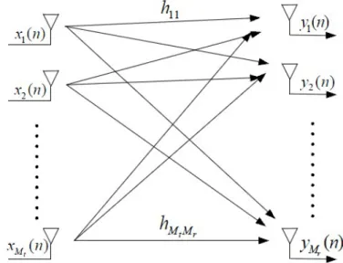
to a factor that is the same as the rank of the MIMO matrix [82, 83]. Con-sider a point-to-point MIMO channel with Mt transmit antennas and Mr
receive antennas as shown in Fig. 2.8. The received signal is given by
y(n) =Hx(n) +η(n), (2.4.1)
where y = [y1(n) · · · yMr(n)]T and yr(n) is the received signal at the rth
receiver antenna. H∈CMr×Mt and hij is the complex channel gain between
the ith transmitter antenna and jth receiver antenna. x(n) ∈ CMt×1 and η(n)∈CMr×1 are the transmitted symbol vector and the noise vector at the receiver end respectively. It is assumed that the channel gain matrix H is
Figure 2.8. A MIMO system with Mt transmit antennas and Mr
receive antennas..
known to both the transmitter and the receiver. The MIMO channel matrix Hcan be decomposed using the Singular Value Decomposition (SVD) as [84]
H=UΣVH, (2.4.2)
where U ∈ CMr×Mr and V ∈ CMt×Mt are unitary left and right singular matrices of H. Σ∈RMr×Mt is a diagonal matrix consisting of the singular
Section 2.4. Spatial Multiplexing Techniques 30
values (υi) of H. RH number of singular values are nonzero, so that RH is
the rank of the matrixH. The singular value satisfies the propertyυi =
√
λi,
whereλiis theitheigenvalue ofHHH. These MIMO spatial subchannels are
obtained using linear transformation of the input signal and the output signal through transmit precoding and receiver shaping. In transmit precoding, the modulated symbol is precoded as
x=V˜x, (2.4.3)
where x˜ is the modulated symbol stream. Similarly, the received signal is shaped as
˜
y=UHy (2.4.4)
as shown in Fig. 2.9. Such transmit precoding and receiver shaping
de-Figure 2.9. Transmit precoding and receiver shaping.
compose the MIMO channel into RH number of independent single-input
single-output (SISO) channels as follows:
˜
y = UH(Hx+η)
= UHUΣVHV˜x+UHη
= Σ˜x+ ˜η (2.4.5)
where ˜η = UHη. The resulting parallel spatial subchannels are shown in Fig. 2.10. They are independent from each other in the sense that signals
Section 2.4. Spatial Multiplexing Techniques 31
through each spatial subchannels do not interfere with each other. Hence
Figure 2.10. Parallel decomposition of the MIMO channel.
this MIMO channel can support upto RH times the data rate of a SISO
channel.
2.4.2 MIMO-OFDM
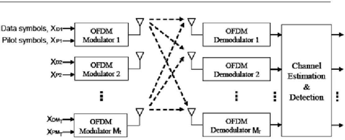
MIMO wireless technology in combination with orthogonal frequency divi-sion multiplexing (MIMO-OFDM) is an attractive air-interface solution for next-generation wireless local area networks (WLANs), wireless metropoli-tan area networks (WMANs), and fourth-generation mobile cellular wireless systems [85–88]. The main motivation for using OFDM in a MIMO chan-nel is the fact that OFDM modulation turns a frequency-selective MIMO channel into a set of parallel frequency-flat MIMO channels. MIMO-OFDM combines OFDM and MIMO techniques thereby achieving spectral efficiency and increased throughput. A MIMO-OFDM system transmits independent OFDM modulated data from multiple antennas simultaneously. At the re-ceiver, after OFDM demodulation, MIMO decoding on each of the subchan-nels extracts the data from all the transmit antennas on all the subchansubchan-nels, as depicted in Fig. 2.11.
Section 2.4. Spatial Multiplexing Techniques 32
Figure 2.11. MIMO-OFDM system
Because the OFDM system effectively provides numerous parallel nar-rowband channels, MIMO-OFDM is considered a key technology in emerg-ing high-data rate systems such as 4G, IEEE 802.16, and IEEE 802.11n [52, 87–89]. For a MIMO system withNT transmit antennas andNR receive
antennas, the channel equation can be expressed asNT×NRmatrix for each
OFDM subcarrier. Each element is denoted byhi,j,k, whereidenotes theith
transmitting antenna,j denotes thejthreceiving antenna andkdenotes the
kth subcarrier. For simplicity, the subscript of thekth subcarrier is ignored. Therefore, the MIMO channel matrix shown in Fig. 7.2.2 can be express as:
H= h1,1 h2,1 · · · hNT,1 h1,2 h2,2 · · · hNT,2 .. . ... . .. ... h1,NR h2,NR · · · hNT,NR (2.4.6)
The transmit signal vector from NT antennas is shown below:
x= [x1x2· · ·xNT] (2.4.7)
multipli-Section 2.4. Spatial Multiplexing Techniques 33
cation in the frequency domain, as shown below: r1 r2 .. . rNR = h1,1 h2,1 · · · hNT,1 h1,2 h2,2 · · · hNT,2 .. . ... . .. ... h1,NR h2,NR · · · hNT,NR x1 x2 .. . xNT + n1 n2 .. . nNT (2.4.8)
The MIMO technique explained earlier can be applied to each subcarrier.
2.4.3 Related works on Spatial Multiplexing Technique
The MIMO-OFDM techniques have been widely studied in the literature from different perspectives including transceiver design [90, 91], resource al-locations [34, 92, 93] and estimation [94–96] and synchronization [97, 98]. In the work of [95,96], the channel estimation has been considered and the chan-nel capacity have been increased in a MIMO-OFDM system. Rate balancing has been achieved in [22]. An adaptive MMSE multiuser detection scheme has been combined with prior information of the channel and interference cancelation in the spatial domain in [99].
Resource allocation technique based on combined MIMO and OFDM techniques has been identified as one of the most promising physical-layer feature for achieving high capacity, high spectral efficiency, and good perfor-mance in dispersive channels [100–102]. Multiuser wireless system based on MIMO-OFDM is considered in [100]. In [100] multiple users are allocated in each OFDM subchannel based on their spatial correlation between the users. The spatial correlation between two users were obtained using the vector multiplication of both users’ spatial subchannel gains. High spatial correlation between users can cause high inter-user interference. Hence, users with lower spatial correlation are allocated in the same subchannel. After user-subchannel allocation, greedy algorithm is used to allocate transmission power in order to satisfy the QoS requirement for each user.
Section 2.5. Wireless Relay Networks 34
2.5 Wireless Relay Networks
A relay network refers to a broad class of network topology commonly used in wireless networks, where the source and destination are interconnected by means of some nodes. In such a network the source and destination cannot communicate to each other directly because the distance between the source and destination is greater than the transmission range of both of them, hence the need for intermediate node(s) known as relays.
2.5.1 One Way Relay Network
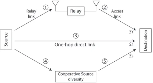
Various relay communication techniques have been studied to improve the capacity and/or expand the coverage of wireless networks [3,15,26,29,37,92]. A classical three-node relaying model has been originally proposed by Van der Meulen in 1971. This network as shown in Fig. 2.12 includes three basic factors: only one source, such as Mobile Multihop Relay-Base Station (MMR-BS); a relay, that may be fixed, nomadic, or mobile, and only one destination, for instance, Mobile Station (MS), or User Terminal (UT).
S our ce Relay Cooperative Source diversity
One-hop direct link
D estina tion Relay link Access link S1 S2 S3 1 2 3 4 5
Figure 2.12. Three-node relay network and cooperative relaying.
The physical channels between source and relay, as well as the one be-tween relay and destination are called relay link and access link respectively.
Section 2.5. Wireless Relay Networks 35
The relay does not receive and transmit using the same channel simulta-neously. In other words, the relay works in half-duplex mode. This is because the received signal is difficult to be separated from the transmitted signal. Therefore, there are two orthogonal subchannels with the channel which is allocated for the relay operation. Take Time Division Duplex (TDD) as an example. There are two orthogonal subchannels of consecutive time slots. The relay receives during the first time slot and uses the second time slot for retransmission.
The concept of cooperative relaying is based on the fact that a signal can be received by multiple terminals and transmitted to destination. The inherent diversity of the relay channel is frequently exploited by the com-bining of received signal constructively at the destination. The details of various level of cooperation will be discussed later.
A cooperative relay network that models transmission between one pair of source-destination through a set of N relay nodes is shown in Fig. 2.13.
Figure 2.13. One way relay network
A two-phase protocol is employed for transmission of data where the re-lays in the network observe signal s transmitted by the source in the first phase (broadcasting phase). The relays transmit their signals to the
![Figure 1.1. The mobile spectrum in Europe [1].](https://thumb-us.123doks.com/thumbv2/123dok_us/10190243.2921734/25.892.222.697.622.931/figure-the-mobile-spectrum-in-europe.webp)